


List of Symbols
General.Symbols which are explained where they occur in the text are only listed if they appear again subsequently.
-
A Flow-law parameter
-
α Amplitude of sine function
-
c Areal concentration of rock fragments
-
c v Debris concentration by volume
-
F Contact force between rock fragment and the bed
-
F f Frictional force
-
g Gravity acceleration
-
g i Vector of gravity acceleration
-
h Glacier thickness
-
l Length of separated bed area
-
N Effective pressure
-
n Flow-law parameter
-
n i Unit normal vector
-
p Pressure (general)
-
P 0 Ice-overburden pressure
-
P w Water pressure
-
P w Separation pressure
-
P w Critical pressure
-
P* Debris concentration
-
p w Normal stress
-
Δp max Amplitude of normal stress
-
R Radius of rock particle
-
r Roughness of the glacier bed (= α/»)
-
s Bed-separation parameter
-
t ij Stress tensor
-
t′ ij Stress deviator
-
t′II Second invariant of stress deviator
-
u i Velocity vector
-
u Velocity-vector component
-
u b Basal sliding velocity
-
u d Velocity due to internal deformation
-
u s Surface velocity
-
U bf Basal sliding velocity in the case of friction
-
U bw Basal sliding velocity in the case of bed separation
-
U bwf Basal sliding velocity in the case of bed separation and friction
-
U t Velocity at the top of the modelled section
-
v n Velocity component normal to the sliding interface
-
x,y,z Cartesian coordinates
-
y b Transverse coordinate describing the base
-
α Mean inclination angle of basal surface
-
β Inclination angle of basal surface
-
δ ij Kroncckcr delta
-
έ ij Strain-rate tensor
-
η Viscosity
-
λ Wavelength of bed undulation
-
μ Coefficient of friction
-
v Poisson’s ratio
-
ξ Coefficient of bed geometry (Reference HalletHallet, 1981)
-
ρ Mass density
-
τ Shear stress
-
τ b Effective basal shear stress
-
τ f Frictional drag
Introduction
Observations in accessible subglacial cavities (e.g. Reference Vivian and BocquetVivian and Bocquet, 1973) and borehole photography (Reference Engelhardt, Harrison and KambEngelhardt and others, 1978) suggest that the classic sliding theories, based on the assumption of clean ice, should be modified to allow for the effect of basal debris.
Detailed measurements of velocity and subglacial water pressure at Findelengletscher (Swiss Alps) were done by Reference Iken and BindschadlcrIken and Bindschadlcr (1986). Their results agree qualitatively with current sliding theories. However, the measured water-pressure values are too large compared to the observed sliding velocities. According to theory, the glacier should in some cases have reached the state of accelerated motion (Fig. 1). This, in fact, is not the case. It was supposed that friction between the dirty basal ice and the glacier bed prevents the glacier from slipping off.
Sliding velocity versus subglacial water pressure showing the discrepancy between theory (a) and observation (b) modified from Reference HutterIken and Bindschadler (1986).

Only a few attempts have been made to include friction in the sliding law. Reference MorlandMorland (1976b) studied some sort of Coulomb friction, but without regard to the actual physical processes at the sole. Reference BindschadlcrBindschadlcr (1983) implicitly made the same assumption by defining a bed-separation index I ~ τ/Ν which is equivalent to the friction coefficient. Reference Boulton and CoatesBoulton (e.g. 1974) has dealt in full with the problem of friction in connection with abrasion and erosion, especially in the case of sediment beds. He argued that the normal load of ice is the relevant variable, an assumption probably true if the debris concentration is very large. Reference HalletHallet (1981) developed a physical model based on what really could happen at the ice–rock interface if the debris concentration is small.
This study investigates the influence of debris concentration in the basal ice on the sliding velocity of a glacier for various debris concentrations. The actual conditions where certain types of friction apply are defined and the consequences for the sliding law are formulated. The classic Coulomb friction is modified in accordance with the notion that a glacier is rubbing over its bed like a piece of sandpaper (Reference DrewryDrewry, 1986). The main objective then is to extend Hallet’s concept to the general case of sliding on an undeformable bed, including both debris friction and the effect of subglacial water pressure. Hallet assumed that friction occurs due to rock particles which, embedded in the basal ice, are pressed against the rigid, impermeable rock bed and dragged along. This process acts on the upstream side of bed undulations. As the frictional force depends on the local velocity field, a numerical approach is required. The numerical modelling of the sliding of an ice mass over an undulating bed, including the effect of both the subglacial water pressure and the friction, is done by solving the problem by the finite-element method. It is not possible to give a simple sliding law, but the present study can provide an idea of which variables are relevant and how they could be included in a realistic relation.
Basic Model
All considerations, analytical as well as numerical, are based on the following glacier model with corresponding assumptions and boundary conditions (e.g. Reference HutterHutter, 1983).
Considering ice as an impermeable, viscous, isotropic, incompressible fluid at constant temperature results in the following set of equations for a mathematical ice-flow model:


expressing the mass conservation (1), the balance of momentum (2), and the constitutive relation between strain-rate tensor and deviatoric stress tensor (3). The Einstein convention for vectors, tensors and deviations was used in the above. Stated in more detail;
-
u i Velocity vector
-
ρ Density of ice
-
t ij Stress tensor
-
g i Vector of external forces (gravity)
-
έ ij Strain-rate tensor

-
t′ ij Deviatoric stress tensor.
-
p Hydrostatic pressure
-
ρ ij Kronecker symbol.


The upper boundary condition (stress-free surface) is

The basal boundary condition for the case of no ice–bedrock separation is either the no-slip condition

or the perfect-slip condition

where ns are unit normal vectors. For the case of non-vanishing tangential stress, this means if there is friction between the ice and the bed, Equation (5b) becomes

where τfi, is the vector of the tangential traction or the frictional drag. Furthermore, no ice–bed separation and neglecting the process of melting and refreezing of basal ice implies

For the case of bed separation, the boundary condition in the separated area is

where Pw is the water pressure in the subglacial hydraulic system.
A general solution to the above equations for any given glacier geometry has not yet been found because of the non-linearity of the constitutive relation and the complexity of the boundary conditions, and is probably not worth seeking. There are some analytical solutions for special conditions of the two-dimensional flow (e.g. Reference NyeNye, 1959) and the sliding problem (e.g. Reference LliboutryLliboutry, 1968; Reference NyeNye, 1969; Reference KambKamb, 1970; Reference DrewryFowler, 1981), and a great number of numerical solutions for specific situations, some of which solve the sliding problem by the finite-element method: Reference IkenIken (1981), Reference SikoniaSikonia (1982) and Reference MeysormierMeysonnier (1983).
Sliding with Bed Separation — a Brief Review
In the classic sliding theories (Reference WeertmanWeertman, 1957; Reference NyeNye, 1969; Reference KambKamb, 1970), the sliding velocity u b is a function of the basal shear stress τb, a fixed value for a given glacier geometry. Effects of variable water pressure are not included. Hence, it is impossible to interpret seasonal or short-term variations in the surface velocity which, as a matter of fact, do exist (e.g. Reference Aellen and IkenAellen and Iken, 1979).
Increased velocity after heavy melting or rain suggests that water at the base influences the sliding velocity. This occurs mainly from surface meltwater penetrating through the glacier to the bed, and not by means of water originating from internal heat sources. Dye-tracer experiments have often shown that the water flows to the terminus much slower than it would be expected for flow through large cylindrical channels. One may therefore conclude that a more complex system of passageways, channels and connected cavities exists. Thus the water pressure Pw in this complex subglacial hydraulic system can be chosen as a further relevant variable in a realistic sliding law. Since the cavities are interconnected, the water pressure is the same in all cavities, neglecting differences in altitude, described by Reference LliboutryLliboutry (1976) as an interconnected hydraulic regime. However, the hydraulic system itself varies, for instance, at the beginning of the melt season: the cavities grow, passageways between cavities form and tunnels re-open. Reference IkenIken (1981) and Reference Iken, Röthlisberger, Flotron and HaeberliIken and others (1983) calculated and observed that the sliding velocity is at a maximum when the cavities are growing. Both the water pressure and the state of the subglacial hydraulic system influence the sliding velocity (Reference KambKamb, 1987).
Reference LliboutryLliboutry (1958) was the first to point out that, in addition to the two processes introduced by Reference WeertmanWeertman (1957), i.e. regelation and enhanced deformation, a third one, that is, flow with cavity formation, should be considered. Extensive studies on this problem (Reference LliboutryLliboutry, 1958, Reference Hutter1979, Reference Lliboutry1987a, Reference Lliboutryb) have not yet resulted in a definitive sliding law. As a new variable, the effective pressure Ν given by the difference between the ice-overburden pressure Po and the subglacial pressure Pw was introduced. The smaller the effective pressure, the more extended is the bed separation. Cavities in the lee of bedrock bumps reduce the roughness and so increase the sliding velocity. By introducing the effective pressure Ν into the sliding law, it seems possible to explain velocity fluctuations. Reference KambKamb (1970) has already discussed important aspects of bed separation. Fowler (Reference Fowler1986, Reference Fowler1987) reformulated the problem of sliding with bed separation as a Hilbert problem and presented a solution for the case of a periodic bedrock (Reference FowlerFowler, 1986) and of a more general bedrock (Reference FowlerFowler, 1987). He introduced the idea of matched asymptotic expansions, a well-known method in fluid-dynamic boundary-layer theory. Thus, the problem is split into the flow in a basal boundary layer and the outer large-scale or bulk glacial flow. The so-called sliding law is therefore the boundary condition of the outer flow at the smoothed bed, and the somewhat ill-defined terms basal shear stress and basal velocity become clear when seen from this point of view. Ill-defined, because the real boundary condition at the ice-rock interface is the perfect-slip condition, thus the shear stress immediately at the base equals zero. Fowler corroborated Reference LliboutryLliboutry’s (1979) observation that the sliding law strongly depends on the bedrock topography. For the particular case of a sinusoidal bedrock, he found the sliding law to be multi-valued, as the surge behaviour suggests. However, in the case of a more general bedrock the sliding law is no longer multi-valued and therefore the surge phenomenon may be explained by the different state of the subglacial hydraulic system, an assumption which agrees with recent results of the 1982 83 surge of Variegated Glacier (Reference KambKamb and others, 1985; Reference KambKamb, 1987).
Re-Calculation of Bed Separation for a Sinusoidal Bed
The sliding over a perfectly lubricated sinusoidal bed is a well-studied particular case of the sliding problem (e.g. Reference LliboutryLliboutry, 1968). In the section below only the process of enhanced creep is considered; regelation is neglected.
On a sinusoidal bed, the stress distribution normal to the bed can be calculated from the force balance (e.g. Reference Raymond and Col-beckRaymond, 1980, equations 46a, 46b). The pressure which the sliding ice mass exerts vertically on the bed is on average equal to the ice-overburden pressure P 0 = ρgh cos α, but due to the undulating bed, it oscillates: larger than the ice-overburden pressure on the upstream faces of bed undulations and smaller on the downstream faces. In the down-glacier direction, the force balance requires that the sum of components in the x-direction of the normal stress p n(x) is equivalent to the average shear stress τ = ρgh sin α In detail, for a two-dimensional model (Fig. 2) with bed topography

The force balance requires

and

With the approximation of small bed roughness (usually tacitly assumed), the oscillating normal stress can be given

The minimum normal stress is the separation pressure P s which is well established and has been introduced in the classic sliding theories (Reference LliboutryLliboutry, 1958; Reference NyeNye, 1969; Reference KambKamb, 1970; Reference MorlandMorland, 1976a):

The water pressure at which the sliding ice mass attains the state of unstable motion is called critical pressure P c. In general, the critical pressure is below the ice-overburden pressure. Independent of the kind of bed profile, the critical pressure can be written as (Reference IkenIken, 1981)

where β is the angle which the stoss faces make with the mean downstream slope. For the special case ol a sinusoidal bed, the steepest tangent of the stoss face is

and thus

This means that the critical pressure is always half-way between the ice-overburden and the separation pressures

The stress distribution (Equation (9)) which determines the bed separation is changes itself by the bed separation. Hence, the formation of water-filled cavities is distinctly a dynamic process. The subsequent balance considerations, following partly a similar derivation by Reference LliboutryLliboutry (1968), describe only a singular transient state and can help to understand the process of bed separation, but cannot fully describe the dynamics.
Geometry of the model: ice-mass sliding over an undulating bed.

It is assumed that bed separation occurs symmetrically around the inflection point (x = λ/2) on the lee side of a rock bump. Real cavities are probably asymmetrical. The length of the separated zone is 2l (see Fig. 3). The bed separation is described by the bed-separation parameter s = 2l/λ, i.e. generally s gives the proportion of bed separation. In contrast to the derivation by Reference LliboutryLliboutry (1968) which assumes that the mean pressure over the separated area is unchanged by the bed separation, the separation length is determined by considering that the force balance has to be fulfilled in both directions, normal and parallel to the mean bed slope. With these assumptions, the stress distribution along one wavelength of the sinusoidal bed can be given as follows:

The continuity at the end of the cavity requires

Hence, the constant contribution p′ is

and thus

This expression reduces to Equation (9) when bed separation ceases. The amplitude of the fluctuating contribution can be determined by considering the force balance. In the y-direction, the mean stress perpendicular to the bed has to be equal to the ice-overburden pressure P 0. As the stress distribution is symmetrical about the inflection point in the lee of the bed undulation, only half a wavelength is considered.

It follows that

or

An additional relation follows from the force balance in the x-direction

Evaluation of the integrals gives

By combining Equations (14) and (15), one gets a functional relationship between the subglacial water pressure and the bed separation

Figure 4 shows the bed separation as a function of the subglacial water pressure. In contrast to the theories of Reference LliboutryLliboutry (1968), Reference FowlerFowler (1986) and Reference KambKamb (1987), the ice is practically fully separated from the bed at the critical pressure which seems to be the crucial variable. Neglecting the force balance in the x-direction, and assuming instead that the mean stress on the separated area is the same as before separation (an assumption which may hold for small separation only), leads to a much smaller bed separation, indicated in Figure 4 by a broken line. In that case, at the critical pressure the bed separation parameter is not s = 1 but s = 0.6 and reaches s = 1 at the ice-overburden pressure. This misunderstanding may have given rise to an overrating of the effective pressure Ν which in the authors’ opinion should not appear in a realistic sliding law.
Bed geometry and stress distribution before p n(x) and after p′ n(x)bed separation.

Bed separation as a function of the subglacial water pressure for a sinusoidal bed: (a) without friction, (b) with sandpaper friction (μ = 0.03, Equation (26)). Broken line indicates erroneous solution assuming that the mean pressure over the separated area is unchanged. Normalized representation  = (Pw–Ps)/(P0–Ps).

A Possible Sliding Law
A realistic, easy-to-use boundary condition for large-scale motion of temperate glaciers and particularly warm-based ice sheets is still not in sight. Nevertheless, simple sliding laws are frequently used by the modellers (Reference BentleyBentley, 1987) without regard to the physical processes. Commonly, they use the “generalized Weertman law” of the form

Reference Budd, Keage and BlundyBudd and others (1979) and Reference BindschadlcrBindschadlcr (1983) fitted their data to such a relation and proposed α = β = 1/3. Thus, the sliding law can be given in the popular form

Hence, no sophisticated law but a very crude relation between some of the relevant parameters is used.
From the theoretical treatment of the sliding over a sinusoidal bed, it seems clear that one of the pertinent variables to introduce in a sliding law is the critical pressure, more precisely the difference between the acting water pressure and the critical pressure. The expressions proposed below are intended to give an idea how a possible sliding law could look

where [ub ] is a dimensionless sliding velocity.
Equation (18) differs substantially from Equation (17) particularly where Alpine valley glaciers are considered. In the case of ice sheets where the basal shear stress is small, the difference between Equations (17) and (18) may be small.
Rock-To-Rock Friction at the Sliding Interface
In most of the theoretical work, frictionless sliding is assumed (Reference WeertmanWeertman, 1957; Reference LliboutryLliboutry, 1968; Reference NyeNye, 1969, Reference Nye1970; Reference KambKamb, 1970; Reference MorlandMorland 1976a; Reference DrewryFowler, 1981). In reality, friction plays an important role and its effects can be seen via erosive patterns such as grooves and striae on rock bumps in the forefield of glaciers. Basal ice generally contains debris in varying concentrations and sizes. When a glacier slides over a bed of rigid or deformable substrata, there is some rock-to-rock friction which slows down the sliding motion. There is no uniform theory of friction. Many findings seem to be preliminary and extremely dependent on the actual circumstances in play (Reference SzeriSzeri, 1987). The experimental “laws” governing friction, namely (1) friction is proportional to the normal load, and (2) friction is independent of the apparent area of contact, are known as Coulomb friction. In the case of glaciers, this concept applies under special circumstances only. Since the basal ice is an ice-rock mixture, the kind of friction should depend on the concentrations of the components. The more rock particles there are in the ice, the stiffer the basal ice layer. The proportion of debris in the basal layer determines the kind of friction concept which applies: Coulomb, “sandpaper” or “Hallet” friction.
Coulomb Friction
Coulomb friction is friction between rigid bodies. There is no motion at the sliding interface except if the shear stress due to the weight driving the sliding mass is large enough to overcome the frictional drag. In general, this is not an appropriate model for glaciers. It may apply in the extreme case where a thick layer of heavily debris-laden ice at the glacier sole is essentially undeformable.
A rigid body with a rough surface is not entirely in contact with the bed, but is so only at a limited number of asperities. In the case where water exists at the bed, the pressure the ice exerts on the bed is reduced by the water pressure P w and the mean normal stress is approximately equal to the effective pressure TV. Therefore, the friction law can simply be written (Reference Boulton and CoatesBoulton, 1974) as:

where μ is the coefficient of friction. For realistic values of the friction coefficient, sliding is only possible at very high values of water pressure (close to the ice-overburden pressure) or on a steep surface slope (Fig. 5).
Coulomb friction: dependence, of sliding on dimensionless water pressure [Pw] = Pw/P0 and friction coefficient μ. Three cases are considered with different mean bed slopes: tan α = 0.05, 0.1, 0.2. Above a line, sliding (for a given mean bed slope) is possible, since [Pw] is large enough or μ is small enough.

Sandpaper Friction
The concept that will be referred to as sandpaper friction is based on a two-layer model consisting of a thin sediment layer poor in ice and a very thick layer of more or less clean ice. In the sediment layer, the rock particles are close together; the ice can no longer flow around them and is simply the glue holding the clasts together, yet due to the ice the basal layer is deformable. Between the rock particles in the layer and the rock bed there is Coulomb friction. Hence, the basal layer rubs over the bedrock like a piece of sandpaper (Reference DrewryDrewry, 1986). The difference between “sandpaper” and Coulomb friction is that the ice mass is really everywhere in contact with the bed, since the basal layer is deformable and adapts to the contours of the bed. The principal difference is visible and decisive if a subglacial water pressure is in operation. In this case, water-filled cavities form and cover a proportion s of the bed; friction is restricted to the contact area, a proportion 1 — s of the bed. If the bed roughness is small and bed separation not too large, the projections of the contact areas on a plane parallel to the mean bed slope do not differ significantly from the actual contact areas. Therefore, the mean pressure P n on the contact areas can be calculated readily from the force balance perpendicular to the mean bed slope:

The frictional stress on the contact areas is

and hence the frictional drag, related to the whole glacier-bed area, is

The frictional drag gets smaller if water pressure is in operation, but is not, as usually assumed, proportional to the effective pressure N. The friction is not reduced as a consequence of a smaller effective pressure, but as a result of the smaller contact area. Since, in general s < 1, the sandpaper friction is larger than the Coulomb friction for a given water-pressure value

Friction along the sliding interface causes higher limiting values for both the separation and the critical pressure. An additional force is required to move the ice mass upward along the steepest tangent of the undulating glacier bed. In the following derivation, a water-pressure value near to the critical pressure is considered where the friction is restricted to a small contact area around the inflection point (Reference IkenIken, 1981, Fig. 1). This contact area does not differ significantly from its projection on to a plane parallel to the steepest tangent (cf. Fig. 2). The force balance normal to this plane is given by

The frictional force Ff opposing the motion upward along the steepest tangent follows as

and hence the frictional stress is

Since near the critical pressure s = 1 the second term (τ tan β) is by far the smallest and can be neglected, the frictional drag can be given by Equation (22) as in the case of small bed roughness and not too large bed separation. Thus, for two extreme conditions, namely s ≈ 0, and s ≈ 1, the same expression was derived. One may therefore suspect that Equation (22) also holds for intermediate values of s.
The critical pressure P′ c in the case of friction can be calculated from the force balance in the direction of the steepest tangent

inserting the expression for the frictional stress (Equation (23)) yields

Neglecting again the smallest term in Equation (23), the critical pressure in the case of friction can be given as

Replacing the driving shear stress by its effective value, τ – τ f, the separation pressure P′ s in the case of friction can be given accordingly as

Before the ice separates from the bed (s = 0), the frictional drag is τ f = μΡ 0 and hence

The expressions for the separation and critical pressure (Equations (24) and (25)) could also have been derived from the relation describing the dependence of the bed separation on the subglacial water pressure (Equation (16)) replacing again the driving shear stress by its effective value

and evaluating the two extreme cases where s = 0 and s = 1, respectively. The effect of friction on the bed-separation process is shown in Figure 4 (line b) by an example where the friction coefficient is μ = 0.03. That the friction slightly changes the stress distribution has been neglected.
As can be seen in Figure 4 and by comparing the expressions for the separation and the critical pressure (Equations (24) and (25)), the effect of friction on the separation pressure is much more pronounced than on the critical pressure since the frictional drag is reduced by increasing water pressure. Thus, the separation pressure approaches the critical pressure for already small values of the friction coefficient, e.g. for a sinusoidal bed with rather large roughness τ = 0.16; this is the case for μ = 0.2 (for smaller roughness values, e.g. r = 0.05, the separation pressure is equal to the critical pressure at a friction coefficient μ = 0.06). This means, for larger values of the friction coefficient, the sliding motion of an ice mass is constant (probably equal to zero), independent of the water pressure, unless the critical pressure is exceeded. In that case, the glacier switches to the state of unstable motion (see Fig. 6, line c).
Functional relationship between the water pressure and the sliding velocity with-out (a) and with sandpaper friction (b), (c) (values with apostrophes). Line (c) reflects the feature that for large friction the separation pressure can exceed the critical pressure. Thus, as long as the water pressure is below the critical pressure, the sliding motion is uniform. At the critical pressure the ice mass switches at once to the state of unstable motion.

Influence on the Sliding Motion
We again assume that the friction leads to a reduction of the driving shear stress. The resultant effective shear stress is called basal shear stress  = τ —. Τf
Accordingly, the proposed functional relationship between subglacial water pressure and (dimensionless) sliding velocity (Equation (18)) is modified

where primes denote variables depending on friction. Figure 6 shows qualitatively the effect of sandpaper friction on the sliding motion. Line (a) gives the relation for debris-free ice; lines (b) and (c) indicate a possible relation between subglacial water pressure and sliding velocity for debris-rich basal ice. In case (b), the separation pressure is below the critical pressure. Line (c) illustrates the above-mentioned “stick-slip” motion for large values of the friction coefficient.
Hallet Friction
When the basal debris is rather sparse, the contact force F pressing the rock particles to the bed no longer depends on the ice-overburden pressure. According to Hallet (Reference Hallet1979, Reference Hallet1981), the contact force F is proportional to the ice velocity v n normal to the bed. Friction only occurs on surfaces along which ice converges with the bed, which corresponds to positive values of v n. On the lee side of the bumps, v n is negative and hence there is no friction.
If again it is assumed that the driving shear stress is partly used for deformational motion and partly for overcoming the frictional drag, the sliding velocity u b is (according to a linear sliding law):

where u
b is basal sliding velocity;  is a constant describing bedrock roughness and ice viscosity; τ is average shear stress at the base (due to gravity); τf is frictional drag.
In Hallet’s notation, the above equation is written as follows:

where ξ is coefficient of bed geometry; η is ice viscosity; μ is coefficient of friction; c is areal concentration of rock particles in contact with the bed; F is contact force between rock fragments and the bed (proportional to the ice velocity v a normal to the bed).
A weak point in Hallet’s theory is that he tacitly assumed that there are always rock particles available on the upstream side of rock bumps. Reference ShoemakerShoemaker (1988) has shown, based on the fundamental work of Reference RöthlisbergerRöthlisberger (1968), that a rock particle embedded in the basal ice is able to contribute only once to friction and then is absorbed, if, as Hallet assumed, the melting rate is neglected. However, in large-scale strained areas (e.g. where the glacier flows over a step or a riegel) sufficient rock particles are transported to the bed, so that the Hallet friction concept applies. Since the frictional term in the sliding law depends itself on the sliding velocity, an iterative solution procedure is necessary.
Numerical Simulation of Sliding with Bed Separation and Friction
The problem of glacier sliding defined by Equations (1)–(5) is solved numerically for the special case of a sinusoidal bed by the finite-element method using the existing two-dimensional FE-codc RHEO-STAUB. The influence on the basal sliding velocity of bed topography, of constitutive relation, of water pressure and of friction (of the Hallet type) at the ice–rock interface was studied. The FE-code used in this study is based on a hybrid stress model for the linear elasticity equations. It was developed for rock mechanics problems at the Institut für Bauplanung und Baubetrieb der ΕΤΗ Zürich (IBETH) (Reference FritzFritz, 1981; Reference Fritz and ArnFritz and Arn, 1983).
General Assumptions of the Numerical Model
The standard assumptions are made: constant density, constant temperature and incompressibility of the ice. Two kinds of constitutive relations are considered: a Newtonian and a non-Newtonian called Glen’s flow law. In terms of second deviatoric stress and strain-rate invariants,  and


where η is the viscosity and accordingly the non-linear flow law

where A and n are the flow-law parameters. From a compilation of different flow-law parameters by Reference PatersonPaterson (1986), numerical values were chosen: n = 3 and A = 3.5 × 10⁻¹⁵kPa−3s−1 = 0.11 bar−3 a−1 corresponding to a temperature close to the melting point of ice at atmospheric pressure. For n = 1 and τ = 1.18 bar = 118 kPa, a value for the viscosity η can be determined by 2η = 1 /AT′2 to η = 2.06 × 10¹³ Pas.
The glacier-sliding problem over an undulating bed is studied in a longitudinal section along the flow direction. The whole glacier is assumed to be 200 m thick and the average slope is 0.1, corresponding to an angle of 5.7°. Our focus is on the bottom boundary condition and therefore on the lowest meters of a glacier or ice sheet. Hence, only a section of 25 m × 60 m is chosen for simulation of the flow and not the entire ice mass. The boundary conditions around the small section arc adapted accordingly Wavelengths of 6, 10, 20 and 30 m were considered. In addition to the wavelength, the roughness is varied: 0.02, 0.05, 0.10. For comparison, actual values, measured at Findelengletscher (Monte Rosa, Swiss Alps), are a wavelength of 20–50 m and a bed roughness of about 0.02 (Reference SchweizerSchweizer, 1989).
Three cases of bottom boundary conditions are considered: no slip (for testing), perfect slip and sliding with friction. It is always assumed that the ice mass rests on an impermeable and undeformable bed: a classic “hard bed” (Reference PatersonPaterson, 1986).
Sliding with friction between the rock bed and particles embedded in the basal ice is simulated using the friction model of Reference HalletHallet (1981), appropriate in the case of sparse debris. In general, the dimensions and concentration of the rock particles and the sliding velocity normal to the bed arc the pertinent variables. The frictional drag is (Reference HalletHallet, 1981, Equations (1) and (2)), for R*. = R:

where  is the factor of the viscous drag of a sphere near the bed, R* is the radius of rock particle and P, is the transition radius analogous to the transition wavelength. The velocity v
n normal to the bed will be determined by the computation. The other variables are constants for a particular case in the numerical simulation. The following values are chosen:

c = 2.5 m−2 corresponds to an areal concentration of one-tenth of a close packing of spherical particles, i.e. in an area of 1 m2, 2.5 particles of 10 cm radius are in contact with the bed. Hallet defined a debris concentration P* = 4R2
c, where P* is the part of the bed effectively covered by debris. The maximum possible concentration (P* = 1) represents a close cube packing of spherical particles all in contact with the bed. The model Hallet developed is applicable for debris concentrations P* smaller than about 30%. Assuming identical layers, one upon another, with twice the particle radius thickness, the areal concentration can be related to the more usual concentration per volume c
v = 2/3πR
2
c, e.g. P = 2.5 m−2 (R = 0.1 m) corresponds to c
v = 0.05. Since not all particles contribute with the whole cross-sectional area to the areal concentration, the concentration per volume, calculated above, is a lower boundary. More realistic for the case considered would be cv = 0.1, which means 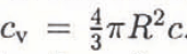 . Hence, we assume that an areal concentration of c = 2.5 m−2 corresponds to about 10% debris per volume of basal ice.
The normal velocity v n is determined at the centre of the spherical particle. As the FE-mesh is not fine enough, the velocity 10 cm above the bed is interpolated from the velocity value in the first node about the bed (about 60 cm above). At the bottom, the normal velocity is of course zero, since the ice slides along the bed. v n is partly positive (on the upstream side of rock bumps where the ice flows towards the bed), about zero (at the top of the bumps) and partly negative (on the leeward side where the ice flows away from the bed). For instance, the vertical velocity 1 m above the bed is 50 cm a−1, if the basal sliding velocity is 17.3 m a−1. It is assumed that the normal velocity decreases linearly with depth. Thus, at the centre of the spherical rock particles (R = 10 cm), the normal velocity is about 5 cm a−1. Figure 7 shows some velocity values normal to the bed above a bump.
Distribution of the sliding velocity normal to the bed some meters above a rock bump (for comparison: Ub = 17.3 m a−1). Flow direction from right to left. “+” sign denotes positive values of the normal velocity (which means the ice flows towards the bed), “−” sign denotes negative values, respectively.

By varying the amount of friction, different values of the concentration c are selected. In principle, the particle radius R or the friction coefficient μ could also be changed with a similar effect. The friction varies as the friction coefficient and as the square of the particle radius. This follows from Equation (31) and the assumption of linearly decreasing normal velocity. Therefore, assuming R* = R, it does not really matter which of the variables, debris concentration, particle size or friction coefficient, are changed; the effect on the sliding can be the same.
Bed separation occurs if the subglacial water pressure is larger than the minimal normal stress the ice exerts on the glacier bed. The effect of the water pressure is simulated by introducing a force normal to the local bed slope. The force corresponding to a certain given water pressure is basically active in all nodes where the normal stress is smaller than the water pressure. However, the separation area is larger than the area where the normal stress is smaller than the water pressure. This fact is known (e.g. Reference IkenIken, 1981) and the separation area was chosen according to the relationship between water pressure and cavity length given above (Equation (16)).
Test Computations
To test the model and the solution method described, the results of the numerical computation were compared with the closed-form solution of the laminar glacier-flow problem and the solutions of Reference NyeNye (1969) and Reference KambKamb (1970) for sliding over a sinusoidal bed.
For the flow of a parallel-sided slab of ice on an inclined plane, the calculated velocity vectors and stress components generally agree within 1% with theoretical values. Inaccuracies up to 3% exist only at the edges due to the fact that the nodal values are mean values. The typical bulging velocity profile of laminar non-Newtonian flow can be perfectly reproduced. In agreement with Glen’s flow law (with n = 3), a change of the basal shear stress leads to a three times larger change in the surface velocity.
The results of simulations of the sliding with a linear flow law are compared with the solution of Reference NyeNye (1969). Nye’s solution which considers a bed geometry with only one wavelength substantially larger than the transition wavelength (thus regelation can be neglected), can be given as

With the values of the model defined above (called principal model): λ = 20 m, τ = 1.75 bar, r = 0.05, η = 1 × 10¹³Pas, one obtains a sliding velocity of u b = 17.2 ma−1.
The numerically calculated velocity is U b = 17.3 m a−1. At the top of the modelled section, the velocity is U t = 28.4 m a−1; thus, the dcformational part of the motion is U d = 11.1 m a−1.
The properties of ice as an incompressible, linear viscous fluid are reflected in the feature of the flow or velocity field (Fig. 8). Figure 9 shows the stress field represented by principal stresses. At first sight, it can easily be seen that the modelled section is well balanced, that more or less laminar-flow conditions prevail at the top and that large compressive stresses exist on the uphill side of the bumps. A number of pertinent variables along the ice–rock interface are compiled in Figure 10. As shown above (Equation (9)), the pressure that the ice exerts on the bed oscillates between 6.35 and 28.6 bar. Reference NyeNye (1969) suggested that the basal sliding velocity varies as the wavelength and as the inverse of the second power of the roughness. This dependence and also the velocity values could be reproduced by the numerical computations.
Velocity field of the principal model, representing the motion, (including sliding) in the lowest 25 m of a 200 m thick ice mass. Thin lines are contour lines of constant velocity. Numbers are velocity values in ma−1.

Stress field of the principal model represented by principal stresses. All stresses are compressive. Thin lines are contour lines of constant effective stress  Numbers indicate effective stress values in tenths of bars (1 bar = 105 Pa).

Numerically calculated values for the principal model along the sliding interface of normal stress Pn, normal component of sti•ess deviator t’n, normal velocity Vn, sliding velocity U b and bed topography yb

The results of the simulations of the sliding of an ice mass over an undulating bed, considering non-linear viscous ice rheology, can be compared with the treatment of Reference KambKamb (1970). The numerically calculated sliding velocities were substantially smaller compared to the ones determined by Kamb’s solution. Since his derivation is based on several idealizations and approximations, we do not disregard our numerical model.
Choosing the same numerical values as above, one arrives at a numerically calculated sliding velocity of U b = 47.4 m a−1. At the top of the modelled section (25 m above the bed), the total motion in 1 year is U t = 86.2 m a−1. Hence, the creep velocity is U d = 38.8 m a−1. Theoretically, the creep velocity in the lowest 25 m of a 200 m thick slab of ice should be 24.3 m a−1. The additional contribution, 18.3 m a−1, is an effect of strain softening.
Table 1 provides an overview of sliding velocities calculated for some models with different geometry. The sliding velocity does not vary as the inverse of the fourth power of the roughness. The dependence on the roughness is stronger than in the linear viscous case but not as strong as Reference KambKamb (1970) proposed (Fig. 11). For different roughness values and wavelength λ = 20 m, the effect of enhanced creep due to strain softening is studied (Table 2). The larger the roughness, the higher the stress concentrations, and creep is enforced accordingly.
Dependence of dimensionless sliding velocity on roughness according to sliding theories by Reference NyeNye (1969) and Reference KambKamb (1970) and derived by finite-element solution using a non-linear flow law.

Compilation of numerically calculated velocity values (in ma−1) compared to exact values from the Nye solution. To each pair of roughness and wavelength two values are given: the upper one originates from the closed-form solution of Nye and the lower one is numerically computed

Sliding and deformational part of the motion (in ma−1) for varying roughness (wavelength λ = 20 m). There are: UL, velocity at the top of the modelled section; U b, velocity at the bed; U d, velocity due to deformation; U ss, velocity due to strain softening. It follows: Ut = U b + U d +U ss, U d is taken from the results of the model simulating the flow of the whole ice mass: Ud = 21.7 ma−t

Sliding with Friction
The next step in simulating the sliding of an ice mass over an undulating, rigid bed is to introduce a friction at the sliding interface due to a dirty, debris-rich basal ice layer. Thus, a frictional force parallel to the bedrock slowing down the motion is introduced, specified in accordance with Hallet’s friction model (Equation (31)).
For three different geometries, the effect of increasing debris concentration on the sliding velocity is studied. The results are given in Figure 12. The computed sliding velocities are generally too small since the frictional force, proportional to the normal velocity, is calculated from the model without friction. Thus, to get an appropriate result, one is forced to use an iterative procedure. Convergence within three digits is reached after about ten steps. The iterations are done for the principal model (λ = 20 m, r = 0.05) for two different debris concentrations: c = 3.75 and 6.25 m−2. The calculated sliding velocities are U bf = 13.6 and 11.8 m a−1, respectively, as indicated in Figure 12 by a broken line. Compared to the frictionless sliding, the velocities are reduced to 78 and 67%, respectively.
Dependence of reduced, sliding velocity (normalized to the frictionless value) on the areal debris concentration for three models with different geometries. Dashed line gives iterative solution for the principal model.

For the principal model with a debris concentration of c = 3.75 m−2, the normal stress along the sliding interface oscillates substantially less than in the case of no friction. Varying between 26.5 and 9.1 bar, the amplitude of the stress oscillations is only Δp max = 8.66 bar. The normal stress amplitude can be given (Equation (9)) as

and, inserting the shear stress τ = ρgh sin α = 1.75 bar, leads to a stress amplitude of 11.1 bar, thus larger than numerically calculated. The minimal normal stress, giving the onset of cavity formation, is increased from 6.4 to 9.1 bar. As wavelength and amplitude of bed undulation are constant, the smaller amplitude of the normal stress must be due to a smaller driving shear stress reduced by friction. Inserting the stress amplitude of the numerical computation (8.66 bar) into Equation (33), a basal shear stress τ b = 1.36 bar results, only 78% of the shear stress due to gravity (τ = ρgh sin α = 1.75 bar). This reduction of the shear stress is in perfect agreement with the reduction of the sliding velocity. The shear stress used to overcome the friction is τ – τ b = τ f 0.39 bar.
There are some computations done for the case of a non-linear flow law of ice (Fig. 13). The sliding velocity is much more reduced than in the case of the linear flow law. Without iterative procedure, a debris concentration of c = 3.75 m−2 prevents any sliding motion. Applying the iterative procedure to determine the frictional force, the large effect of friction on the sliding velocity would be attenuated. An estimation for that is given in Figure 13 based on the computation for the case of a linear flow law. There it is shown that the reduction of the sliding velocity corresponds to a reduction of the driving shear stress, in particular for a debris concentration of c = 3.75 m−2 a reduction to 78% was found. Using a non-linear flow law such as Glen’s flow law with exponent n = 3, it seems obvious that the sliding velocity would be reduced to (0.78)3 = 0.48.
Dependence öf reduced sliding velocity on the areal debris concentration for the principal model with a non-linear flow law. Dashed line gives estimated iterative solution.

Sliding with Bed Separation
Frictionless sliding with bed separation as an effect of subglacial water pressure has been studied in detail by Reference IkenIken (1981). In particular, the transient stages of growing and shrinking of water-filled cavities at the ice–bedrock interface were analysed. The introduction of a frictional drag at the sliding interface is the innovation of the present study. In this context, the effect on the separation and the critical pressure is of main interest. The present work does not extend to the point where the cavities reach a steady-state shape. Except for one, all computations are done using a linear-flow law.
Bed separation, and hence the onset of cavity formation, starts when the subglacial water pressure reaches the minimal normal stress, known as separation pressure. In the case of the principal model (λ = 20 m, r = 0.05), the separation pressure (Equation (10)) is given as P s= 6.35 bar and the critical pressure (Equation (11)) as P c = 11.91 bar. For studying the effect of the subglacial water pressure on the sliding velocity, eight different models with increasing water-pressure values between 6.35 and 11.64 bar were chosen. Figure 14 (upper left curve) contains the results of the numerical computations of the corresponding sliding velocities showing the very typical relationship between the sliding velocity and the subglacial water pressure. For a given shear stress, the sliding velocity is a constant, as long as the water pressure is below the separation pressure. Then, the velocity increases progressively with increasing water pressure tending to infinity at the critical pressure.
Dependence of the basal sliding velocity Ub on both the subglacial water pressure Pw and the basal debris concentration c. The sliding velocities are normalized to the velocity which was calculated without friction and without bed separation. Upper left line gives the case of frictionless sliding. Two cases with c = 2.5 m−2 and c = 5.0 m −2 are considered. Horizontal lines at left side represent the state before bed separation starts. Dashed vertical lines (asymptotes) give the critical pressure, rising with increasing debris concentration. Linear flow law is used.

Up to this point, the two effects of bed separation and of friction due to debris in the basal ice were studied separately. Combining the two important variables, subglacial water pressure and areal basal debris concentration will show, for instance, whether the friction is enforced if the ice is separating from the rock bed.
Figure 15 shows that the reduction of the sliding velocity due to friction is more pronounced in the case of bed separation. Again, the iterative solution indicated in Figure 15 by the lower broken line is estimated from the results of the computation for the case of no bed separation. Comparing the iterative solutions, computed for the case of no bed separation and estimated for the case of separation P w = 10.8 bar), the friction increased by about 50% if a water pressure is in operation.
Dependence of basal sliding velocity (normalized to the corresponding case of no friction) on the areal debris concentration. Solid line gives the residts in the case of bed separation for a water pressure Pw = 10.8 bar. Dashed lines show iterative solutions in the case of no bed separation (P w = 0) and in the case of bed separation (Pw = 10.8 bar). Linear flow law is used.

How the sliding velocity in the case of friction is dependent on the water pressure is studied for two different debris concentrations: c = 2.5 and 5.0 m−2. Hence, in contrast to the computation above, the amount of friction is constant but the separation area increases with increasing water pressure. The larger the debris concentration, the later the separation starts. Figure 14 shows the results of the numerical computations of sliding with friction in the case of bed separation for both, varying debris concentration and varying water pressure. The typical relationship between sliding velocity and subglacial water pressure remains valid, also in the case of friction. However, the curves are shifted to the right, to larger water-pressure values. This simply means separation and critical pressure are larger in the case of friction.
The critical and the separation pressures depend on the normal stress amplitude Δp max which is as shown above smaller in the case of friction than without. For a debris concentration of c = 3.75 m−2 (and the geometry of the principal model), a stress amplitude of Δp max = 8.66 bar has been calculated numerically. Based on this result and the fact that the normal stress amplitude varies as the effective value of the driving shear stress, the stress amplitude for the debris concentrations c = 2.5 and 5.0 m−2 can be determined by a linear interpolation to 9.48 and 7.84 bar, respectively. These calculated values of the normal stress amplitude can be used to calculate the separation and the critical pressure in the case of friction. Table 3 is a compilation of calculated values of the separation and the criticial pressure based on the numerical computation of the normal stress amplitude. Figure 14 shows clearly that the pressure values calculated in the way described above coincide with the values which can be drawn from the illustration. In contrast to the theoretical considerations on the effect of “sandpaper” friction, the numerical calculations showed that in the case of “Hallet” friction the critical pressure stays half-way between the separation and the ice-overburden pressure, i.e. Equation (12) remains valid.
Separation (P s) and critical pressure (P c) (in bar) of the principal model for different debris concentrations (c in m−2); ice-overburden pressure P 0 = 17.5 bar

Discussion of Actual Conditions
Based on the Hallet friction model and on the assumption of a sinusoidal bedrock with unrestricted access of the subglacial water to all low-pressure zones at the glacier bed, the measured relation between water pressure and sliding velocity could be qualitatively reproduced. However, while this model predicts the critical pressure to be the arithmetic mean of separation pressure and the overburden pressure (Equation (12)), no instability of the glacier was observed at water pressures significantly below the overburden pressure (Fig. 1). Several reasons for this discrepancy are conceivable: on a more general bed, different values of maximum slope of stoss faces exist. It is the obstacles with the steepest stoss faces which determine the critical pressure and, in particular, if obstacles with vertical stoss faces arc present, the critical pressure approaches the overburden pressure. Steep stoss faces are, however, typically absent in the gently undulating, polished bedrock, now exposed in the forefield of Findelcngletscher. This bedrock might be more adequately described as a series of roches moutonnées. Obviously, Equation (12) does not hold for roches moutonnées which typically have steep lee faces. In that case, the separation pressure is much lower (Reference IkenIken, 1981), whereas, assuming that the undulations have the same maximum slopes of the stoss faces as the modelled sinusoids, the critical pressure is unchanged. Furthermore, the assumption of unrestricted access of the subglacial water to all low-pressure zones is not realistic. If zones with insufficient water supply do exist, the growth of cavities and the increase in water storage, an indispensable prerequisite to an acceleration at the critical pressure, is prohibited. Hence, these zones slow down the speed-up of the glacier.
In the models considered, the debris concentration has been assumed as given. Actually, it is the result of a balance (or imbalance) of processes which increase or diminish the debris concentration at the base: large-scale ice deformation, basal melting and plucking versus flushing by subglacial streams and wear-off of the abrading particles. For instance, the basal debris concentration increases continually in a zone of large-scale vertical compression, e.g. the accumulation zone, where particles move from the surface to the base of the glacier. On the other hand, where an overall vertical compression is absent, the abrading particles finally loose contact with the bed, in spite of local vertical compression at stoss faces of small-scale bed undulations. Thus, even Hallet’s friction mechanism can only be maintained with some kind of particle rcsupply, for instance, plucking as pointed out by Reference ShoemakerShoemaker (1988). Where plucking occurs, simple Coulomb friction between newly plucked particles and the bed can also operate temporarily. After a certain time, the particles will be incorporated into the ice and the Coulomb friction will be replaced by Hallet friction. However, in zones of intensive plucking, this type of transient Coulomb friction may contribute significantly to abrasion as Reference Boulton and CoatesBoulton (1974) assumed without regard to the limited duration of the process.
The type of friction acting influences the surface velocity and its variations. A few measurements of the surface velocity may therefore give a hint to the actual conditions at the glacier bed. This is illustrated by two examples: Findelengletscher and Unteraargletscher, both of which are large valley glaciers in the Swiss Alps. The first one is sliding all the time and a small debris concentration will cause friction of the Hallet type. Unteraargletscher, on the other hand, is rather slow-moving and debris-covered in the lower part. An examination of the particular seasonal velocity variations shows that the sliding velocity is negligible, except during the melt season. The basal debris concentration seems to be high and hence sandpaper friction is acting. These two examples may be seen as representatives of two types of glaciers: fast-sliding, actively eroding glaciers with small debris concentration, and debris-rich glaciers where sub-glacial rock deposition is a dominant process. This distinction may supplement a classification of glaciers sug-gested by Reference HaeberliHaeberli (1986).
Conclusions
Based on the theory of frictionless sliding over a sinusoidal bed (Reference LliboutryLliboutry, 1968; Reference NyeNye, 1969; Reference KambKamb, 1970), a relation is developed between the subglacial water pressure and the bed separation in which the critical pressure is a pertinent variable. This relation is of crucial importance for studying the effect of friction in the case of bed separation.
Two friction processes have been examined in detail: “sandpaper friction” and “Hallet friction”. The former applies to large debris concentrations (> 50% per volume) with particles being in close contact and is a sort of Coulomb friction adapted to the case of glaciers. “Hallet friction” is only active at small debris concentrations when particles do not contact each other. “Sandpaper friction” decreases with increasing water pressure, whereas “Hallet friction” was found to be independent of water pressure. Both types of friction give rise to larger values of both the separation and the critical pressure. However, since the dependence of the friction on the sub-glacial water pressure is different, the effect on the separation and the critical pressure also differs. In the case of “Hallet friction”, the critical pressure is the arithemetic mean of separation pressure and ice-overburden pressure, no matter how large the debris concentration or the friction coefficient. In the case of “sandpaper friction”, the separation pressure increases more strongly with the friction coefficient than the critical pressure and therefore may approach the critical pressure.
The typical relation between sliding velocity and sub-glacial water pressure found by Reference Iken and BindschadlcrIken and Bindschadler (1986) could be reproduced qualitatively with the “Hallet friction” model. However, a quantitative agreement could not be achieved for the particular idealizations this study was based on.
An approximate sliding law which makes allowance for the effect of friction and includes the criticalpressure has been formulated (Equation (27)).
Sliding with sandpaper friction can only take place in times of high subglacial water pressure; at other times the friction prevents any sliding motion. Therefore, glaciers with a sandpaper sole will only slide in the melt season, as long as sufficient subglacial water storage can be maintained. Duringother seasons, rock deposition rather than erosion occurs. In contrast, glaciers with small basal debris concentration, where Hallet friction applies, slide and abrade throughout the year.
Acknowledgements
The authors wish to thank W. Haeberli and M. Funk for critically reading and discussing the manuscript. Many thanks to R. Bindschadler and A. Fowler who helped to improve the paper by their constructiveand thorough reviews. B. Nedela prepared the drawings and S. Braun-Clarke edited the English. This study was subsidized by Swiss National Science Foundation grant No. 2000–4.748.
The accuracy of references in the text and in this list is the responsibility of the author, to whom queries should be addressed.



