1. Introduction
Among a number of structural features suggestive of meteorite impact on Earth, shatter cones are the only macroscopic features currently accepted as evidence for shock metamorphism (e.g. French & Short, Reference French and Short1968; French, Reference French1998; Langenhorst, Reference Langenhorst2002; French & Koeberl, Reference French and Koeberl2010). First described at the Steinheim Basin (Baden-Württemberg, SW Germany; Figs 1, 2) by Branco & Fraas (Reference Branco and Fraas1905) more than 100 years ago as the ‘Steinheimer Strahlenkalke’, and still interpreted as of cryptovolcanic origin at that time, shatter cones were later recognized to be associated with – and restricted to – meteorite impact structures (e.g. French & Koeberl, Reference French and Koeberl2010). Structurally and genetically, shatter cones are oblate, spoon-shaped to almost conical, or curvilinear fracture phenomena characterized by a distinct striation along the long (‘cone’) axis that is thought to form in response to rapid and dynamic tensile stresses during impact (e.g. Sagy, Reches & Fineberg, Reference Sagy, Reches and Fineberg2002; Sagy, Fineberg & Reches, Reference Sagy, Fineberg and Reches2004) by the interference of shock waves with target rocks at shock pressures in excess of ~ 2 GPa (e.g. Baratoux & Melosh, Reference Baratoux and Melosh2003). Recent reviews of shatter cone formation are provided by, for example, Baratoux & Reimold (Reference Baratoux and Reimold2016 and references therein) and Osinski & Ferrière (Reference Osinski and Ferrière2016). Sizes of individual shatter cones may vary from some millimetres (e.g. this study) to >10 m (e.g. at the Slate Islands impact structure, Ontario, Canada; Sharpton et al. Reference Sharpton, Dressler, Herrick, Schnieders and Scott1996; French, Reference French1998). In the Steinheim Basin and many other smaller impact structures, shatter cones are known from rocks that form the crater floor of the impact structure. In the Steinheim Basin, well-developed shatter cones are known from Upper Jurassic limestones of the structural crater floor mainly from the southern and eastern part of the crater (e.g. Heizmann & Reiff, Reference Heizmann and Reiff2002). Schmieder & Buchner (Reference Schmieder and Buchner2013), moreover, described morphologically variable shatter cones from concretions of the Middle Jurassic Opalinus Claystone that builds up the central domain of the central uplift.
Shaded relief image of the eastern Swabian Alb plateau showing the position of the Steinheim Basin (dashed line indicates ~ 3.8 km crater diameter), the adjacent valleys, a main morphological feature – the Alb escarpment – and the position of the city of Heidenheim an der Brenz (see small map for position of the scene in SW Germany; Shuttle Radar Topography Mission data, 2-fold vertical exaggeration).

Schematic cross-section of the Steinheim Basin displaying the main sedimentary units of the Steinheim target rocks and the position of the Middle Jurassic ‘Opalinus Clay’ layer with the sampling locality of the Opalinus Claystone shatter cones on the top of the central uplift and of the Upper Jurassic limestone shatter cones in rocks forming the crater floor (modified from Schmieder & Buchner, Reference Schmieder and Buchner2013; after Mattmüller, Reference Mattmüller1994). Approximately 1.5-fold vertical exaggeration.

Earlier studies by Gay (Reference Gay1976), Gay, Comins & Simpson (Reference Gay, Comins and Simpson1978), Gibson & Spray (Reference Gibson and Spray1998) and Nicolaysen & Reimold (Reference Nicolaysen and Reimold1999) investigated the composition of exotic melting- and vaporization-related microfeatures (spherules, as well as melt splats and fibres) adherent to shatter cones from the large, eroded Vredefort impact structure in South Africa and the Sudbury Basin in Canada, respectively. A recent study by Schmieder et al. (Reference Schmieder, Chennaoui Aoudjehane, Buchner and Tohver2015) reported brecciated schreibersite and Fe–Ni oxide flakes on the surface of a limestone shatter cone from a recently identified impact site at Agoudal in Morocco (e.g. Lorenz et al. Reference Lorenz, Ivanova, Artemieva, Sadilenko, Chennaoui Aoudjehane, Roschina, Korochantsev and Humayun2014; Schmieder et al. Reference Schmieder, Chennaoui Aoudjehane, Buchner and Tohver2015). Similarly, microparticles of meteoritic affinity were recently detected on shatter cones from the structural crater floors of the Ries crater in Germany (Buchner & Schmieder, Reference Buchner and Schmieder2016a), the East Clearwater Lake impact structure in Québec, Canada (Buchner & Schmieder, Reference Buchner and Schmieder2016b; compare Grieve, Palme & Plant, Reference Grieve, Palme and Plant1980), and the Marquez Dome impact structure in Texas, USA (Schmieder & Buchner, Reference Schmieder and Buchner2016), respectively. The exotic particles adherent to the shatter cones are interpreted as possible impactor traces. Motivated by these findings, we here investigate shatter cones from concretions of the Middle Jurassic Opalinus Claystone sampled on the top of the Steinheim Basin central uplift, and shatter cones in Upper Jurassic limestones of the crater floor collected on fields inside the southeastern crater rim (see Figs 2, 3).
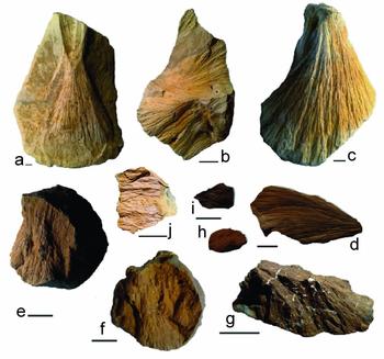
Typical shatter cones in Upper Jurassic (Kimmeridgian–Tithonian) limestones at Steinheim (a–d) and in concretions of the Middle Jurassic Opalinus Claystone (e–j): (a) Hourglass-like shatter cone with positive (convex, above) and negative (concave, below) individual cones running in opposite directions; (b) nested aggregate of shatter cones building up a ‘horsetail’-structured limestone specimen (below) and a negative individual shatter cone (above); (c) well-developed larger individual cone; (d) well-developed individual cone investigated in this study (SC-L1; Table 2) coated with carbon for SEM–EDS analysis; (e–j): shatter cones in Middle Jurassic Opalinus Claystone nodules: (e, f) horsetail structure with a set of nested positive (convex) individual shatter cones running in one main direction across the whole nodule; (g) well-defined shatter cone in claystone showing white, opalescent remnants of fossil shells; (h) small Opalinus Claystone shatter cone individual investigated in this study (SC-C2; Table 1), not carbon coated; (i) small Opalinus Claystone shatter cone individual investigated in this study (SC-C3; Table 1), carbon coated; (j) Opalinus Claystone shatter cone covered by a bright, shiny coating; sample courtesy: Peter Seidel, Steinheim am Albuch. Scale bars are 1 cm. Shatter cone photographs compiled from Schmieder & Buchner (Reference Schmieder and Buchner2013) and from shatter cones of the impactite collection at the Institut für Mineralogie und Kristallchemie, Universität Stuttgart, curated by the authors.

2. The Steinheim Basin: geologic setting
The ~ 3.8 km diameter Steinheim Basin, centred at 48° 41ʹ N, 10° 04ʹ E, about 42 km SW of the centre of the Ries crater, is a complex impact crater with a prominent central uplift formed in a sequence of Triassic and Jurassic sedimentary rocks that build up the karstified limestone plateau of the eastern Swabian Alb (Baden-Württemberg, SW Germany; e.g. Reiff, Reference Reiff1976, Reference Reiff, Roddy, Pepin and Merrill1977; Hüttner & Schmidt-Kaler, Reference Hüttner and Schmidt-Kaler1999; Heizmann & Reiff, Reference Heizmann and Reiff2002; Ivanov & Stöffler, Reference Ivanov and Stöffler2005; Buchner & Schmieder, Reference Buchner and Schmieder2015; Figs 1, 2). A minor portion of the target rocks probably involved Palaeogene (bog iron ore-type ‘Bohnerz Formation’) to Neogene (sandy deposits of the Miocene ‘Upper Freshwater Molasse’) sediments. Owing to the protective post-impact sedimentary cover, among which are fossil-rich Miocene crater lake sediments, the Steinheim Basin is one of the best-preserved complex impact craters on Earth (e.g. Heizmann & Reiff, Reference Heizmann and Reiff2002). The morphological crater rim exhibits inclined and brecciated blocks and clods of Upper Jurassic (Kimmeridgian to Tithonian) marine limestones (Heizmann & Reiff, Reference Heizmann and Reiff2002; Reiff, Reference Reiff2004) locally rich in chert nodules. A mainly carbonatic lithic impact breccia (earlier referred to as ‘Primäre Beckenbrekzie’ by Groschopf & Reiff, Reference Groschopf and Reiff1966, Reference Groschopf and Reiff1969) is known from numerous drillings into the Steinheim Basin (Reiff, Reference Reiff2004) and contains variable amounts of lithic clasts of Middle to Upper Jurassic limestones, marls, mudstones and sandstones.
Although there is still no striking evidence for higher levels of shock metamorphism in mineral grains, the Steinheim Basin is well known for its brecciated rocks and shatter cones (mainly in micritic limestones) of exemplary shape and quality (e.g. Dietz, Reference Dietz1959, Reference Dietz1960; Dietz & Butler, Reference Dietz and Butler1964; von Engelhardt et al. Reference Engelhardt, Bertsch, Stöffler, Groschopf and Reiff1967; Heizmann & Reiff, Reference Heizmann and Reiff2002; Fig. 3). Melt lithologies from the Steinheim Basin were reported by Buchner & Schmieder (Reference Buchner and Schmieder2010; carbonate-dominated suevitic impact breccia) and Anders et al. (Reference Anders, Buchner, Schmieder and Kegler2013; carbonatic impact melt rock). Isotopic dating has, so far, not yielded a geologically meaningful age (e.g. Buchner et al. Reference Buchner, Schwarz, Schmieder and Trieloff2013). The Steinheim impact structure is thought to have formed simultaneously with the ~24 km Nördlinger Ries crater by the impact of a binary asteroid at 14.83 ± 0.15 Ma (Di Vincenzo & Skála, Reference Di Vincenzo and Skála2009; see also Buchner et al. Reference Buchner, Schwarz, Schmieder and Trieloff2010, Reference Buchner, Schwarz, Schmieder and Trieloff2013), which is roughly consistent with the Miocene post-impact crater lake biostratigraphy at both impact craters (Reiff, Reference Reiff1988, Reference Reiff2004; Stöffler, Artemieva & Pierazzo, Reference Stöffler, Artemieva and Pierazzo2002; Buchner et al. Reference Buchner, Schwarz, Schmieder and Trieloff2010, Reference Buchner, Schwarz, Schmieder and Trieloff2013; and see Schmieder et al. Reference Schmieder, Trieloff, Schwarz, Buchner, Jourdan, Miljković, Collins, Mannick and Bland2014 for discussion). Findings of Fe–Ni–Co sulfides and Fe–Ni-droplets associated with the Steinheim melt lithologies were interpreted to suggest an iron meteoritic impactor (Schmieder & Buchner, Reference Schmieder and Buchner2009, Reference Buchner and Schmieder2010b; Buchner & Schmieder, Reference Buchner and Schmieder2010; Anders et al. Reference Anders, Buchner, Schmieder and Kegler2013).
Deformation caused by the Steinheim impact mainly affected Jurassic sedimentary rocks. Crater-filling impact ejecta deposits contain abundant clasts of Upper to Middle Jurassic rocks, whereas fracturing, faulting and structural uplift (~ 350 m at the centre of the Steinheim Basin) reach down to the Upper Triassic (the continental ‘Stubensandstein’ Keuper sandstones; e.g. Heizmann & Reiff, Reference Heizmann and Reiff2002; Reiff, Reference Reiff2004; Buchner & Schmieder, Reference Buchner and Schmieder2013b, their fig. 4). Middle Jurassic (Upper Aalenian) iron-rich and locally shatter-coned marine ‘Eisensandstein’ sandstones (e.g. Schmieder & Buchner, Reference Schmieder and Buchner2013, their fig. 4) build up the flanks of the central uplift. At the centre of the Steinheim central uplift (locally known as the ‘Steinhirt’ and ‘Klosterberg’ hills south of the village of Steinheim am Albuch; Fig. 2), the Middle Jurassic (Lower Aalenian) marine, black shale-type ‘Opalinuston’ Claystone formation (attaining up to >100 m in thickness in Eastern Württemberg; Geyer & Gwinner, Reference Geyer and Gwinner1991; Reiff, Reference Reiff2004) crops out and locally causes surficial effects of waterlogging (visible in the field at the ‘Lettenhülbe’ pond situated on top of the central uplift). The strongly squeezed Opalinus Claystone strata are in an almost upright position in the upper parts of the central uplift and still show a ~ 60° basin-ward inclination at a depth of 200 m (Reiff, Reference Reiff1976; Heizmann & Reiff, Reference Heizmann and Reiff2002).
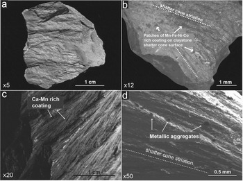
Coatings on Middle Jurassic claystone shatter cones (a, b) and on Upper Jurassic limestone shatter cones (c, d). In some rare cases, thin coatings can cover the entire shatter cone surface (a); they mostly occur in patches (b) or are aligned along the shatter cone striations (c), or as single aggregates randomly distributed on shatter cone surfaces (d).

3. Samples, sample localities and analytical techniques
Shatter cones in the Middle Jurassic Opalinus Claystone were sampled on top of the Steinheim central uplift (Steinhirt; 48° 41ʹ 07″ N, 10° 03ʹ 50″ E) during water catchment works in April 2010; Figs 2, 3; see also Schmieder & Buchner, Reference Schmieder and Buchner2013, their fig. 5, for images of the temporary exposure). Shatter cones of the ‘classical’ Steinheim-type in Upper Jurassic limestones (Fig. 3) were collected on fields halfway between the northern flank of the ‘Burgstall’ (48° 40ʹ 30″ N, 10° 04ʹ 19″ E) and ‘Knill’ (48° 40ʹ 34″ N, 10° 04ʹ 38″ E) hills close to the southeastern rim of the Steinheim Basin. In this study, we investigated 11 shatter cone specimens (between ~ 1 and ~ 3 cm in size) taken from six different Opalinuston Claystone nodules. The occurrences of rare metals were detected on five of these shatter cone individuals; these samples are denominated ‘Shatter Cone Claystone 1–5’ (SC-C1 to SC-C5) in the following. Furthermore, we analysed four larger (between ~ 4 and ~ 6 cm in size) individual shatter cones in Upper Jurassic limestone, referred to as ‘Shatter Cone Limestone 1–4’ (SC-L1 to SC-L4) in the text.
Opalinus Claystone shatter cone (SC-C5), coated by presumed hydrothermal mineralization including aggregates of native gold. (a) Shatter cone surface showing well-developed horse-tail structures (secondary electron image). (b) Shatter cone surface, same as (a) (backscattered electron image); frame shows area with gold aggregates shown in (c) and (d). (c) Small gold aggregates imbedded in shatter cone coating; arrow shows gold aggregate depicted in (d). (d) Single gold aggregate grown on Fe-rich substrate; gold aggregate is covered by a thin Ca- and Fe-rich coating.

Geochemical analyses of the coatings on shatter cone surfaces were carried out by scanning electron microscopy and energy-dispersive X-ray spectroscopy (SEM–EDS) using a CamScan SC44 scanning electron microscope coupled to an EDAX PV 9723/10 system (Institut für Mineralogie und Kristallchemie, Universität Stuttgart), at a beam current of 70 nA and acceleration voltages of 15 and 20 kV. The system is equipped with a conventional Be window Si(Li) detector 13 µm in thickness. Standard counting times were 300 seconds. All analyses are normalized to 100 wt % and oxygen were calculated by stoichiometry. ZAF matrix correction software was used to calculate element concentrations. Imaging was done in secondary electron (SE) and backscattered electron (BSE) mode. To avoid contamination of the shatter cone samples with Au, C or other elements from the sputter apparatus, a certain number of SEM–EDS analyses were carried out on uncoated specimens that were also analysed under high vacuum conditions. Microspec™ olivine, apatite and cryolite (analysed by the Oxford Instruments™ Microanalysis Group) were used as compound standards for EDS analyses. Further standards used (analysed by the Oxford Instruments™ Microanalysis Group) are barite for Ba; pyrite (villamaninite) for S, Ni, Co and Cu; pure platinum for Pt; and pure gold for Au. The accuracy of the analyses varied depending on the roughness of the sample surfaces, but all analyses shown in this study were above the detection limits indicated in the tables.
The very high content in Fe (around 90 wt %; see Table 1, e.g. Fig. 3f) of the coatings of some of the Opalinus Claystone shatter cones and the resultant high conductivity of the surfaces of these shatter cones allows imaging and EDS analyses on uncoated specimens without disturbing charging processes. The SEM–EDS (EDAX PV 9723/10) system of the Stuttgart SEM laboratory is able to detect C and O qualitatively, but not quantitatively. However, the system allows the user to determine with some certainty whether the phases analysed are oxides, carbonates, sulfates or sulfides. Oxygen was analysed qualitatively to discriminate between metal and oxide phases in our samples.
SEM–EDS analyses (SC-C1 to SC-C5) (20 kV) of coatings on the surfaces of five shatter cone individuals in Middle Jurassic Opalinus Claystone concretions

Element values in oxide wt %; normalized to 100 %; EPM analyses on sample SC-C6 were carried out on polished thin-sections of particles scraped from three Opalinus Claystone shatter cone surfaces; the presence of Mn, Fe, Ni and Co in electron probe microanalyses was qualitatively confirmed by WDS scans.
Because of the interferences between Mn, Fe, Co and Ni emission lines, the evaluation of EDS spectra is sometimes difficult. This holds particularly true for the measurement of Co in the presence of Fe and Ni, because the Fe-Kβ line overlaps with the Co-Kα line, and the Co-Kβ line is covered by the Ni-Kα line. We assumed the qualitative presence of Co, if the following two criteria were fulfilled: (1) the Co-Kα line is situated somewhat to the left of the Fe-Kβ line and the Co-Kβ line somewhat to the right of the Ni-Kα line, leading to an asymmetric appearance of the Fe-Kβ and Ni-Kα peaks (when Co-Kα and Co-Kβ lines are covered); and (2) in the case where the Fe-Kβ overlaps with the Co-Kα line, the resultant apparent Fe-Kβ peak will be disproportionally high compared to the Fe-Kα peak.
For verification of the SEM–EDS results, metallic particles were scraped off the shatter cone surfaces using a scalpel and embedded in synthetic resin, from which polished thin-sections were produced and analysed by electron probe microanalysis (EPMA; SC-C6 and SC-L5). In order to prevent contamination of our samples with rare metals, we analysed all tools (hammer, scalpel and tweezers) used in the preparation process. The steel composition of these tools exclusively comprised Fe, Mn, C and Cr. Electron probe microanalysis and wavelength-dispersive spectrometric (WDS) scans were carried out with a CAMECA™ SX 100 electron microprobe equipped with five WDS spectrometers (Institut für Mineralogie und Kristallchemie, Universität Stuttgart). The electron beam diameter was 5 μm at a current of 5/10 nA (35 nA for WDS scans) and an acceleration voltage of 20 kV; standard counting times were 180 seconds. The system is able to detect O qualitatively and quantitatively. The CAMECA™ SX 100 is equipped with PeakSight EPMA automation and analysis software. EPMA precision for standardless analysis is 2–3 % for major elements, but can exceed 10 % for elements with values <2 wt % in individual cases. Estimated accuracy (total EPMA error) amounts to ~ 5 % for major elements. Quantitatively, all elements analysed by SEM–EDS (listed in Tables 1 and 2) were detected well above the EPMA detection limits and background, and all analyses were carried out on individually and randomly composed coatings that do not reflect primary mineral composition. WDS scans, not done quantitatively, were carried out to control EPMA results, particularly the crucial sector of the EDS spectra of Mn, Fe, Ni and Co peak interference.
SEM–EDS analyses (20 kV) of coatings on the surfaces of three individuals of Upper Jurassic limestone shatter cones (SC-L1 to SC-L3)

Element values in oxide wt %; analyses normalized to 100 %; EPM analyses on sample SC-L5 were carried out on polished thin-sections of particles scraped from Upper Jurassic limestone shatter cone surfaces; the presence of Mn, Fe, Ni and Co in electron probe microanalyses was qualitatively confirmed by WDS scans.
4. Petrography and geochemistry
4.a. Coatings on Middle Jurassic Opalinus Claystone shatter cones (SC-C1 to SC-C6)
The Opalinus Claystone in southern Germany is modally dominated by clay minerals (~65 % illite–smectite mixed layers), quartz (~19 % sand and silt), calcite (~13 %) and some accessories such as siderite (Fe-carbonate), pyrite, feldspar and organic carbon (Kobler, Reference Kobler1972; Etzold, Reference Etzold1994; Heitzmann & Bossart, Reference Heitzmann and Bossart2001). Concretionary claystone nodules and competent carbonatic layers characterized by diagenetic cone-in-cone structures (e.g. Selles-Martinez, Reference Selles-Martinez1994; Schmieder & Buchner, Reference Schmieder and Buchner2010a) are commonly observed in the Opalinus Claystone. The nodules are of marly, sideritic and rarely of phosphatic composition, with variable contents of Ca- and Fe-carbonate (Andalib, Reference Andalib1970; Kobler, Reference Kobler1972; Brodbeck, Reference Brodbeck1995). Shatter cones in the Opalinus Claystone have only been found in these rather competent nodules.
Thin coatings on freshly exposed shatter cone surfaces in the Opalinus Clay are visible on the mesoscopic scale as a clear to reddish-yellow, silky ‘patina’ (Fig. 4). In SEM–EDS analyses, the surfaces of all 11 shatter cone individuals revealed coatings (Figs 5, 6) rich in Fe, Ca, P, Si, K and Al (quantified as the respective oxides Fe2O3, CaO, P2O5, SiO2, K2O and Al2O3, for shatter cones SC-C1 through SC-C5, see Table 1) in highly variable proportions that geochemically resemble the cementing material (marl, siderite, phosphate) of the Opalinus Claystone nodules. Furthermore, Mg, Mn, S, Ti, Ni, Co, Cu and Au concentrations are locally in the per cent range. In some of the coatings (in particular, that of sample SC-C4), Ba, S and Ca concentrations are locally elevated owing to the occurrence of secondary barite and/or Ca-sulfate (gypsum/anhydrite) aggregates (see Table 1).
Opalinus Claystone shatter cone (sample SC-C5), covered by Ca- and Fe-rich coating and a Fe–Co–Ni-rich particle. (a) Shatter cone surface showing well-developed horse-tail structures (secondary electron image); arrow shows sector depicted in (b). (b) Shatter cone surface showing well-developed horse tail structures (secondary electron image); arrow shows sector depicted in (c). (c) Fe-rich coating; box shows sector depicted in (d). (d) Fe–Co–Ni-rich grain (Table 1).

Five (SC-C1 to SC-C5) of the 11 studied shatter cone individuals revealed additional elements in the per cent range (see Table 1). EDS-resolvable amounts of Cu and Pt were detected on the surface of samples SC-C1 (Table 1) and SC-C3 (Table 1), respectively. Nickel, cobalt and gold are abundant in nearly every measurement on the five shatter cone individuals SC-C1 through SC-C5 (Table 1). Notably, gold forms very small disseminated micro-grains (SC-C1 and SC-C4; Table 1) or nests of small aggregates of native Au (SC-C5; Table 1). The gold aggregates are commonly coated by a very thin Ca- and Fe-rich layer (quantified as CaO and Fe2O3). In only one case, a homogeneous particle rich in Fe, Ni and Co (quantified as oxides) was found on the surface of an Opalinus Claystone shatter cone. In contrast to the geochemically variable coating, SEM–EDS analyses on the entire grain surface yielded very similar analytical results within relatively narrow limits (SC-C5; Table 1). Samples of the coatings scraped off three claystone shatter cone specimens also contained individual aggregates rich in Fe, Ni, Co and Cu (SC-C6; Table 1).
4.b. Coatings on Upper Jurassic limestone shatter cones
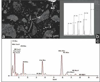
Limestone shatter cones from the Steinheim Basin sometimes exhibit a characteristic brownish or greenish to grey staining (including micro-dendrites of iron and manganese oxides and oxyhydrates; Fig. 4) of the striated surface, on a hand specimen scale. The Upper Jurassic limestones of the Steinheim area are mainly composed of calcite (~80–86 wt % CaO) and dolomite (~0.8–1.2 wt % MgO), some sulfate (~1.3–1.7 wt % SO3), detrital quartz grains and phyllosilicates (~5.1–6.2 wt % SiO2, ~1.7–2.9 % Al2O3, ~1.0–1.7 wt % K2O, ~0.9–2.4 wt % Fe2O3), in variable proportions. The surfaces of two SEM-investigated limestone shatter cones (SC-L1 and SC-L2) show a thin layer rich in CaO and MnO (in the form of calcite and manganese oxides/hydroxides). Furthermore, K-rich phyllosilicates (probably illite as a common mineral in weathered Jurassic limestones, e.g. Kobler, Reference Kobler1972) occur in the limestone shatter cone coatings (see Table 2). Between the shatter cone surfaces and the Ca–Mn-rich coating, some optically darker (light in BSE images) patches rich in Fe, Ni and Co (again, quantified as oxides) are dispersed across the shatter cone surface (SC-L1 and SC-L2; Table 2). Larger aggregates of native gold are not visible in the SEM; however, measured values for Au concentrations reach up to ~0.75 wt % in these patches, obviously caused by finely dispersed Au tinsel. It was technically not possible to analyse the Fe-, Ni-, Co- and Au-rich patches directly, as all these patches were covered by the Mn- and Ca-rich coating (Table 1). Besides Fe, Ni, Co, Cu and Au, no further elements were detected by SEM–EDS measurements in the per cent range. Coatings scraped off shatter cone surfaces showed oxide aggregates enriched in Ca and Mn, as well as in Fe, Ni and Co (SC-L5; Table 2; Fig. 7).
Polished thin-section, with (a) particles of carbonate (light grey) and Mn–Fe–Ni-Co-rich aggregates (white) scraped from the surface of three Upper Jurassic limestone shatter cones (SC-L5), embedded in resin, cut and polished; numbers 1–5 mark locations of EPM analyses. (b, c) Microprobe analyses of Mn–Fe–Ni–Co-rich aggregates (location 1 in (a)), with (b) showing a WDS scan of the crucial sector of the EDS spectrum of Mn, Fe, Ni and Co peak interference.

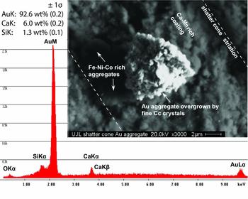
The coating on the surface of an Upper Jurassic limestones shatter cone sample (SC-L3) is dominated by CaO, Fe2O3 and some phyllosilicates, but essentially free of Mn (see Table 2). The shatter cone surface is covered by a macroscopically visible greenish to grey coating, occurring parallel to the shatter cone striation. These coatings exhibit countless aggregates and very fine grains and larger aggregates of native Au (Figs 8, 9; concentrations given as oxide wt %), as well as non-metallic areas with elevated concentrations of Fe, Ni, Co, Cu, Pt and Au in highly variable proportions, embedded in the Ca–Fe-rich coating, which on this shatter cone specimen is nearly free of Mn. Furthermore, a single grain rich in Cu and Zn and multiple barite grains were encountered.
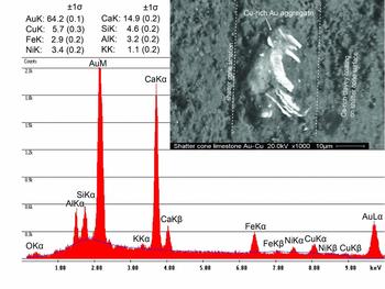
EDS X-ray spectra (15–20 kV) for spots analysed on an Au aggregate embedded in Ca–Mn-rich coating on the surface of an Upper Jurassic limestone shatter cone (SC-L3), as well as the chemical composition of the gold aggregate covered by fine calcite crystals (Cc) and traces of silica. Although Si is quantified as silica and Ca as carbonate (see O peak), Au, Si and Ca abundances are given in element wt %, normalized to 100 %. In addition to this Au aggregate, two roundish Fe–Ni–Co-rich aggregates were encountered.

EDS X-ray spectra (15–20 kV) for spots on an Au aggregate embedded in Ca-rich and phyllosilicate (illite) coating on the surface of an Upper Jurassic limestone shatter cone (SC-L3), as well as the chemical composition of the gold aggregate (Au–Cu–Ni alloy) covered by fine calcite crystals and phyllosilicate minerals. Values are given as element wt %, normalized to 100 %.

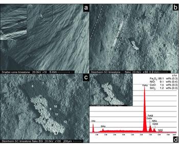
On the surface of limestone shatter cone sample SC-L4 (Fig. 10; Table 3), we detected a single botryoidal flake ~400 µm in maximum length that consists of a ‘lighter’ and a ‘darker’ portion in BSE image mode. Qualitative EDS analysis of oxygen revealed that both phases are, at least at the surface of the aggregate, oxides. Six SEM–EDS measurements on the lighter portion of the flake revealed high values in Fe (~65.2–88.0 wt % Fe2O3), Ni (~7.5–9.1 wt % NiO) and Co (~0.9–2.1 wt % CoO), and a minor content in SiO2, MgO and CaO (Table 3). Some measurements yielded additional significant contents of Cu (≤18.9 wt % CuO), Pt (≤2.1 wt % PtO), Ge (~0.8–2.3 wt % GeO2) and Ga (~0.7–0.8 wt % Ga2O3; Table 3). Six individual measurements resulted in a more siliceous composition of the darker portion of the flake, with high concentrations of silica (~24.4–46.9 wt % SiO2), Al2O3 (~4.3–19.0 wt %), CaO (~6.7–23.1 wt %) and MgO (~2.6–6.3 wt %), versus lower, but still considerable, concentrations of Fe, Ni and Co (given as oxides), compared to the brighter portion of the flake. The darker portion of the flake, however, also revealed notable Cu, Pt, Ga and Ge concentrations in the oxide phase (see Table 3).
Upper Jurassic limestone shatter cone (SC-L4) surface (a) with a Fe–Ni–Co-rich flake (b–d). The flake shows a botryoidal surface texture and exhibits a brighter (metallic) and a darker (more siliceous) portion. (c) shows locations of the 12 SEM–EDS measurements listed in Table 3. (d) shows a typical EDS X-ray spectra (measurement 1 in image (c)); element values in oxide wt %, normalized to 100 %.

Twelve individual SEM–EDS measurements (1 to 6 on the light, metal-rich portion and 7 to 12 on the dark more siliceous portion) on a Fe-, Ni- and Co-rich oxide flake on the surface of an Upper Jurassic limestone shatter cone individual (SC-L4; compare to Fig. 7)

Elements in oxide wt %; normalized to 100 %.
5. Discussion
5.a. Origin of the Steinheim shatter cone coatings
5.a.1. Contamination from the Mesozoic sedimentary target rock?
In the Steinheim Basin area, several of the Mesozoic–Cenozoic sedimentary units can be considered as potential sources for rare metals detected in the coatings on shatter cone surfaces. Calcium carbonate, manganese oxides and minor phyllosilicates, found associated with the surface coating of two Upper Jurassic limestone shatter cones (SC-L1 and SC-L2), are omnipresent in fluids in sedimentary rocks of the Swabian Alb, and commonly form thin coatings on faults, bedding planes and in cavities in the bedrock. The fossiliferous black shale deposits of the Lower and Middle Jurassic (including the Sinemurian ‘Obtusum Claystone’ (Obtususton) Formation; the Pliensbachian ‘Numismalis Marlstone’ (Numismalismergel) and ‘Amaltheus Claystone’ (Amaltheenton) Formations; as well as the Toarcian ‘Posidonia Shale’ Formation (Posidonienschiefer) and ‘Jurensis Marlstone’ (Jurensemergel) Formation; and the lowermost Middle Jurassic Opalinus Claystone, the iron oolithic Middle Jurassic Eisensandstein Formation, as well as the Palaeogene residual deposits of the ‘Bohnerz’ (bog ore) Formation are the most noticeable sedimentary units with respect to a potentially high concentration of trace metals. The main major elements and the most abundant trace elements for the aforementioned sedimentary units are shown in Figure 11 and listed in Table 4. Vanadium (up to 900 ppm), Sr (up to 1720 ppm), Zr (up to 850 ppm), Cr (up to 240 ppm), Zn (up to 3000 ppm) and Pb (up to 790 ppm) concentrations are remarkably high in these units, whereas Ni, Co, Cu and, in particular, Au concentrations are generally low (below ~0.1 ppm). The Opalinus Claystone is characterized by a typical phyllosilicate mineral geochemistry, usually with high Ti and low Mn concentrations (e.g. Fröhlich et al. Reference Fröhlich, Amayri, Drebert and Reich2011). Trace elements are dominated by Ba, Sr, Zr, V, Cr, Rb and Zn (Table 4, columns 1 and 2). The composition of the Middle Jurassic Eisensandstein Formation is dominated by quartz and phyllosilicate minerals, and typically contains up to ~43 wt % of iron oxides and oxyhydrates (e.g. Linhardt & Zarbok, Reference Linhardt and Zarbok2005). The most abundant trace elements in these predominantly iron oolithic sandstones are V, Cr, Ba, Zn, Sr, Rb and As (see Table 4, column 3). Jurassic black schist-type deposits, as exemplified by the Posidonia Shale, also feature a characteristic phyllosilicate mineral geochemistry, with comparatively high Ca and Ti concentrations and low Mn. The dominant trace elements in the Posidonia black shale are Sr, Zn, Ba, V, Cr, As and Pb (e.g. Brumsack, Reference Brumsack, Tyson and Pearson1991; Table 4, column 4). Besides having a phyllosilicate mineral geochemistry, the Palaeogene Bohnerz Formation is dominated by high contents of Fe oxides and oxyhydrates (up to ~70 wt %), as well as Mn, P and Ti. The most abundant trace element is Zn, followed by high V, Pb, Zr, Cr, Sr and As concentrations (e.g. Geyer, Reference Geyer1957; Table 4, column 5). In the literature, Au concentrations are usually not listed for these stratigraphic units, presumably because Au concentrations are negligible (<0.1 ppm in the Posidonia Shale; Brumsack, pers. comm. 2014) and, possibly, owing to technical problems in Au detection in X-ray fluorescence analysis.
Geochemical data for the shatter cone coatings plotted against the data of the sedimentary target rocks (compare to Table 4). The overall trend of the geochemical signature of the shatter cone coatings runs contrary to the geochemical signature of the sedimentary target rocks.

X-ray fluorescence (XRF) analyses of main and trace elements (bulk analyses) of the Middle Jurassic Opalinus Claystone, Lower Jurassic Posidonia Shale, Middle Jurassic Eisensandstein Formation and Palaeogene Bohnerz Formation taken from the literature

For Opalinus Claystone, Posidonia Shale, Eisensandstein Formation and Bohnerz Formation, the seven most abundant trace elements are listed.
5.a.2. Contamination from the Palaeozoic crystalline-metamorphic basement?
The Variscan (Moldanubian) crystalline-metamorphic basement in the Steinheim area is covered by a ~1100 m thick suite of sediments (e.g. Stöffler, Artemieva & Pierazzo, Reference Stöffler, Artemieva and Pierazzo2002). According to Reiff (Reference Reiff1992) and Buchner & Schmieder (Reference Buchner and Schmieder2015), the transient crater of the Steinheim Basin possibly reached a depth of 1200 m and, thus, may have affected the uppermost portion of the basement. However, as all shatter cones analysed in this study formed in Middle and Upper Jurassic rocks, several hundred metres of Triassic to Lower Jurassic sedimentary rocks would have separated the crystalline-metamorphic basement from the stratigraphic levels of shatter coning (and no shatter cones have so far been reported from the Upper Triassic Keuper sandstones in the Steinheim drill cores; compare, e.g. Heizmann & Reiff, Reference Heizmann and Reiff2002; Buchner & Schmieder, Reference Buchner and Schmieder2010). Moreover, no fragments of Variscan crystalline-metamorphic rocks have been found in the crater-filling impact breccia at Steinheim (e.g. Heizmann & Reiff, Reference Heizmann and Reiff2002). Thus, contamination of the shatter cone surfaces with particulate matter directly derived from the deeper crater basement is unlikely. Theoretically, a post-impact hydrothermal system inside and beneath the Steinheim crater may have dissolved Au and other rare metals from the crystalline-metamorphic rocks in the crater basement. Primary gold mineralization types in the Variscan basement comprise gold-bearing ores in the parageneses Au–Cu–Zn–Pb, Au–As–Bi–Mo–Te–W, and Au–Ag–As and secondary Au mineralization usually contains significant amounts of Cu, Ag, Zn, As, Bi and Pb (A. Schmiderer, unpub. Ph.D. thesis, Univ. Halle-Wittenberg, 2008). Whereas Cu was detected on some shatter cone surfaces and Zn was encountered in a single grain on one limestone shatter cone specimen, Ag, As, Bi and Pb were not detected in any of the SEM–EDS analyses carried out in this study. The presence of the elements Au, Ni, Co, Pt and Cu found on the Steinheim shatter cone coatings and the absence of elements such as Ag, Zn, Cr and Pb could theoretically be an effect of the prevailing temperature conditions of the hydrothermal system, or could be caused by fractionation due to differential uptake of different ions in aqueous solutions. According to Zhu, An & Tan (Reference Zhu, An and Tan2011), hydrothermal systems without distinct affinities to magmatic activity and relatively low (epithermal) temperatures of ≤300 °C (as expected for the rather small Steinheim Basin that formed in water-saturated, porous target rocks; Buchner & Schmieder, Reference Buchner and Schmieder2013a, Reference Buchner and Schmieder2015) would result in the formation of hydrothermal ore deposits that may contain Au and elements such as Ag, Zn, Sb and Pb. From this point of view, it seems rather unlikely to consider the Variscan basement rocks as the source for the rare metals found on the Steinheim shatter cones; however, we cannot entirely exclude this possibility.
5.a.3. Anthropogenic contamination?
The occurrences of rare metals on the shatter cone surfaces might be the result of recent (or subrecent) contamination either in the laboratory or in the field. Hundreds of small aggregates of native gold, as well as dispersed individual Au particles of up to 20 µm in size occur on the surfaces of some shatter cones. As Au is a common contaminant in SEM laboratories that use gold sputters, we cannot definitely rule out that we detected some contaminant Au particles on shatter cone surfaces. However, we interpret the vast majority of the Au particles detected as in situ formation for the following reasons: (1) Au particles usually overgrow (or are intergrown with) the shatter cone coatings (SC-C5; compare Fig. 5); (2) many of the Au particles are overgrown by small crystals of calcite (and sometimes silica) and/or by phases of Fe hydroxides or phyllosilicates (compare Figs 8 and 9); (3) the Au particles often represent alloys of Au with Cu, Ni and other metals (Fig. 9). The concentration of Cu in some of the Au particles locally exceeds several wt %. In remarkable contrast, the purity of the gold targets used in the Stuttgart SEM laboratory is at least 99.99 wt %. To avoid contamination of the shatter cone samples with Au, C or other elements from the sputter apparatus, we carried out additional SEM–EDS analyses on an uncoated specimen of Opalinus Claystone shatter cones (CS-C2) that has a Fe-rich natural coating. On the surface of this shatter cone, we detected the same elements as in the coatings of C-coated shatter cones, in particular, high values of Fe, Ni, Co (quantified as oxides) and some Au particles. Gold contamination from the scalpel can be ruled out because the scalpel, used to mechanically scrape off surface coating material from the shatter cone surfaces for thin-sectioning and EPMA, is composed of Fe, Mn, C and Cr.
Moreover, metallurgical processes in the context of historical bog ore smelting may potentially cause subrecent contamination of shatter cone surfaces with rare metals. According to Geyer (Reference Geyer1957), bog ore was mined and smelted in large areas of the Swabian Alb in the Middle Ages; so it was in the greater Steinheim area (e.g. near Heidenheim a. d. Brenz and Königsbronn, only a few kilometres away from the Steinheim Basin). However, the pisolithic Bohnerz and its host clays have been shown to contain only traces of Ni (<500 ppm; Borger & Widdowson, Reference Borger and Widdowson2001). Moreover, we can widely exclude this type of contamination for the Opalinus Claystone shatter cones because these shatter cones were only recently excavated during water catchment works on top of the Steinheim central uplift in April 2010. Furthermore, we only analysed fresh shatter cone individuals never exposed previously, after breaking the intact shattered Opalinus Claystone nodules.
5.a.4. Possible meteoritic contamination from the Steinheim asteroid?
Alternatively, the rare metals concentrated in the coatings of the Steinheim shatter cones may possibly represent the redistributed geochemical relics of the impacting meteorite that formed the Steinheim Basin, earlier proposed to have been an iron or stony-iron meteorite (Schmieder & Buchner Reference Schmieder and Buchner2009, Reference Schmieder and Buchner2010b; Buchner & Schmieder, Reference Buchner and Schmieder2010). The preponderance of Fe, Ni, Co, Cu, S, P and the presence of some resolvable Pt in the shatter cone coatings is compatible with an iron meteorite as the potential source for these elements. The geochemistry of the different types of meteorites is dominated either by silicate minerals in achondrites and chondrites, or by Fe, S, P, Ni and Co in iron meteorites and/or in the metallic portion of stony-iron meteorites. Among the trace elements, Ge, Ga and Cu play a key role. The Au content in achondrites and chondrites is usually very low, whereas stony-iron and, in particular, iron meteorites typically have much higher Au concentrations (e.g. Danielson, Righter & Humayun, Reference Danielson, Righter and Humayun2009; see Table 5) of >5 ppm (Bauer & Schaudy, Reference Bauer and Schaudy1970) and in some cases as high as >18 ppm (Hecht & Fenninger, Reference Hecht and Fenninger1963). For a compilation of the Au concentration in representative meteorites of different types, see Table 5. Iron and stony-iron meteorites contain Fe, Ni and Co in the per cent range, while Cu is usually the most abundant trace element (e.g. Smales, Mapper & Fouché, Reference Smales, Mapper and Fouché1967; Bauer & Schaudy Reference Bauer and Schaudy1970; Wolf, Wang & Lipschutz, Reference Wolf, Wang and Lipschutz2009).
Au concentration (ppm) of some representative meteorites in different meteorite classes. The bulk Au concentration systematically increases from achondrites to iron meteorites

Note that the metallic portions of achondrites, chondrites and stony-iron meteorites also contain high amounts of Au.
The Opalinus Claystone shatter cone (SC-C3) contains relatively high Pt concentrations (≤1.45 wt % PtO, see Table 1). According to, for example, Pernicka & Wasson (Reference Pernicka and Wasson1987) and Tagle & Hecht (Reference Tagle and Hecht2006), Pt is also abundant in iron meteorites. Platinum group element (PGE) ratios have been traditionally used to discriminate between different types of meteorites and to investigate meteoritic contamination (e.g. Evans, Gregoire & Goodfellow, Reference Evans, Gregoire and Goodfellow1993; Koeberl Reference Koeberl, Grady, Hutchison, McGall and Rothery1998, Reference Koeberl, Holland and Turekian2014; Goderis, Paquay & Claeys Reference Goderis, Paquay, Claeys, Osinski and Pierazzo2012). However, although Fe, P, S, Ni and Co concentrations in the coatings on the surfaces of the Opalinus Claystone shatter cones are rather high, they usually do not occur in proportions typical for minerals in iron meteorites (e.g. the Fe–Ni metal phases kamacite or taenite). Thus, these coatings are unlikely to represent primary remnants of the supposedly iron meteoritic Steinheim impactor (compare Schmieder & Buchner, Reference Schmieder and Buchner2009, Reference Schmieder and Buchner2010b; Buchner & Schmieder, Reference Buchner and Schmieder2010 and discussion of possible impactor signatures therein). For a summary of the characteristics and composition of Opalinus Claystone shatter cone coatings see Table 6, SC-C1 to SC-C6).
Compilation of the characteristic properties of all claystone and limestone shatter cones investigated in this study

The composition of the unusual, botryoidal oxide flake on the surface of limestone shatter cone SC-L4 (Tables 3, 6), with elevated concentrations of Fe, Ni, Co, Pt, Ga and Ge (Table 3; given as oxides), also suggests this flake may represent some sort of meteoritic matter. Again, the composition probably does not reflect the primary, but likely altered, element ratios. The average inter-element ratios (Fe/Ni of ~9.5 and Ni/Co of ~7.5) are broadly consistent with the respective whole-rock inter-element ratios of iron meteorites (for instance for octahedrites, e.g. Kracher, Willis & Wasson, Reference Kracher, Willis and Wasson1980; Pernicka & Wasson, Reference Pernicka and Wasson1987), in contrast to most chondrites characterized by a whole-rock Ni/Co of ~20 (e.g. Schmieder & Buchner, Reference Schmieder and Buchner2010b and references therein). The chemistry of the ‘darker’, more silicate-rich, portion of the flake might be comparable to the composition of the silicate part of a stony-iron meteorite (for instance a mesosiderite, e.g. Powell, Reference Powell1971). Moreover, the apparent concentration of Pt, Ga and Ge is arguably too high as though the host flake could be considered ‘original’ meteoritic matter. The botryoidal microtexture of the flake's surface, the high element concentrations of the otherwise rare metals Cu, Pt, Ga and Ge, and, finally, the oxidized mineral phases of the flake argue for an (intensely) altered, potentially meteorite-derived fragment. Any original meteoritic matter may have experienced hydrothermal overprint and partial dissolution, and subsequent local precipitation of Cu-, Pt-, Ga- and Ge-rich oxide phases. Although the interpretation of this unusual flake as oxidized impactor matter remains speculative, the recent finding of several schreibersite aggregates on the surface of a limestone shatter cone from the Agoudal impact site in Morocco (Schmieder et al. Reference Schmieder, Chennaoui Aoudjehane, Buchner and Tohver2015) indicates that shatter cone surfaces may carry both primary and altered meteoritic matter.
In summary, an origin of the shatter cone coatings (or portions of these) as target rock-derived or anthropogenic contamination seems unlikely. As the crucial trace elements (e.g. V, Sr, Zn and Cr) characteristic for the target sediments of the Steinheim Basin and gold-bearing ores in the Variscan crater basement (e.g. Au, Zn, As, Pb) were not encountered in the coatings, we conclude that it is rather unlikely that Ni, Co, Cu and Au were dissolved from the host rocks of the Steinheim Basin impact crater. Owing to the scarcity of detailed information on the trace element concentration in and the lack of information on the Au content of the sedimentary target rocks, we are not able to exclude the upper Steinheim target rocks as a possible source for the rare metals enriched on the shatter cones. The elements concentrated in the shatter cone coatings, however, suggest a general affinity towards a meteoritic source, possibly an iron meteorite. This interpretation is supported by the occurrence of Fe-Ni-Co-sulfides as fragments and droplets in melt particles of the Steinheim Basin impact breccia (Schmieder & Buchner, Reference Schmieder and Buchner2009, Reference Schmieder and Buchner2010b) and Fe-Ni-Co spherules adherent to melt particles therein (Buchner & Schmieder, Reference Buchner and Schmieder2009), as well as by the high concentrations of Au and Cu within Fe-sulfide aggregates in the Steinheim breccia (Buchner & Schmieder, Reference Buchner and Schmieder2010, Reference Buchner and Schmieder2013b).
5.b. Potential influence of impact-induced hydrothermal activity
One possible way to generate surface coatings on shatter cone fractures in the shocked target rock is the post-impact precipitation of elements from hot fluids that circulate in a hot, cooling impact crater (e.g. Zürcher & Kring, Reference Zürcher and Kring2004; Naumov, Reference Naumov2005; Osinski et al. Reference Osinski, Tornabene, Banerjee, Cockell, Flemming, Izawa, McCutcheon, Parnell, Preston, Pickersgill, Pontefract, Sapers and Southam2013; Schmieder & Jourdan, Reference Schmieder and Jourdan2013). The coatings on the surface of all shatter cones analysed, containing chiefly the same elements in variable proportions, could represent an epigenetic mineralization in response to a hydrothermal system that developed inside the fresh Steinheim impact crater. The existence of a post-impact hydrothermal system in the Steinheim Basin, although probably rather short-lived, is supported by the high water content of weathered melt particles in the Steinheim Basin impact breccia (Buchner & Schmieder, Reference Buchner and Schmieder2010, Reference Buchner and Schmieder2013b; Anders et al. Reference Anders, Buchner, Schmieder and Kegler2013), which are almost completely altered into phyllosilicates (compare Osinski, Reference Osinski2005; Muttik et al. Reference Muttik, Kirsimäe, Somelar and Osinski2008), and the presence of a freshwater carbonate spring mound on the central uplift (the ‘Wäldlesfels’; e.g. Heizmann & Reiff, Reference Heizmann and Reiff2002; Anders et al. Reference Anders, Buchner, Schmieder and Kegler2013). Similar to the high water content in the melt particles, the high content of rare metals in framboidal Fe-sulfide aggregates within the Steinheim impact breccia lens (Buchner & Schmieder, Reference Buchner and Schmieder2010, Reference Buchner and Schmieder2013b) and in carbonate melt veins (Anders et al. Reference Anders, Buchner, Schmieder and Kegler2013) suggests that the post-impact formation of authigenic pyrite may be related to impact-induced hydrothermal activity (e.g. Newsom & Hagerty, Reference Newsom and Hagerty2003). The surfaces of the shatter cones represented open microfractures susceptible to the circulation of hydrothermal solutions, and thereby promoting the precipitation of hydrothermal wall deposits. According to Seward (Reference Seward and Foster1991), hydrothermal Au (and other elements, such as Cu and Zn) deposition may occur over a wide temperature, pressure and fluid composition range, and may include lower temperature epithermal mineralization (~50–300 °C). The circulation of solutions in the early post-impact hydrothermal system at Steinheim likely occurred under such low-temperature conditions. Jõeleht et al. (Reference Jõeleht, Kirsimäe, Plado, Versh and Ivanov2005) and Versh et al. (Reference Versh, Kirsimäe, Jõeleht and Plado2005), for example, investigated the hydrothermal system in the ~4 km in diameter, marine Kärdla impact crater in Estonia in detail. This Ordovician impact crater hosted an impact-induced hydrothermal system in the fractured basement rocks inside its central uplift, and in the surrounding impact breccias. The hydrothermal water–rock interaction in heated impactites is usually characterized by a complex mineralization assemblage. Mineral associations suggest at least three evolutionary stages grading into one another. A first, vapour-dominated stage of crater cooling was dominated by elevated temperatures exceeding 300 °C; the main cooling stage saw temperatures between ~300 and 100 °C; and a late liquid-dominated stage was characterized by temperatures below 100 °C. The lowest-temperature stage is associated with the crystallization of late chalcopyrite and pyrite (Versh et al. Reference Versh, Kirsimäe, Jõeleht and Plado2005). As a second example, rocks from drill cores into the 1.9 km diameter Lonar crater in India show basaltic impact breccias altered by post-impact hydrothermal processes, and a corresponding assemblage of secondary alteration minerals (Hagerty & Newsom, Reference Hagerty and Newsom2003). Thermodynamic modelling and terrestrial volcanic analogues were used to demonstrate that this mineral assemblage was formed at temperatures as low as ~130–200 °C. These analogues suggest that the coatings on the shatter cone surfaces of the Steinheim Basin (inside the central uplift, and thus within the structural crater floor) may have been precipitated in the lower, epithermal, temperature range, and that cooling impact craters even smaller than the Steinheim Basin can potentially drive short-lived fluid systems at temperatures sufficient to generate hydrothermal mineral deposits. Numerous barite aggregates associated with one of the Upper Jurassic limestone shatter cones (SC-L3, Table 2) may be examples of secondary, potentially hydrothermally grown or diagenetic, mineral phases.
5.c. Broader significance of ‘exotic’ shatter cone coatings
Koeberl (Reference Koeberl, Grady, Hutchison, McGall and Rothery1998) pointed out that fragments of the impacting projectile are occasionally preserved in smaller impact craters, whereas in most of the larger craters a smaller amount (mostly <1 %) is mixed in with impact melt rocks or breccias. According to French (Reference French1998), most of the impacting projectile is vaporized during a larger impact event. Some rare exceptions in the terrestrial impact cratering record are, for example, the finding of extraterrestrial chromite grains in the resurge breccia of the ≥ 7.5 km diameter Lockne impact structure, Sweden (Alwmark & Schmitz, Reference Alwmark and Schmitz2007) and a larger meteorite fragment preserved in the impact melt sheet of the ≥ 70 km Morokweng impact structure, South Africa (Maier et al. Reference Maier, Andreoli, McDonald, Higgins, Boyce, Shukolyukov, Lugmair, Ashwal, Gräser, Ripley and Hart2006). Therefore, impactor traces in terrestrial impact structures are usually investigated by the intercorrelation of siderophile elements in impact melt lithologies (e.g. Goderis, Paquay & Claeys, Reference Goderis, Paquay, Claeys, Osinski and Pierazzo2012; Koeberl, Reference Koeberl, Holland and Turekian2014). The recent report of schreibersite adherent to a shatter cone discovered near Agoudal in Morocco (Schmieder et al. Reference Schmieder, Chennaoui Aoudjehane, Buchner and Tohver2015) suggests that ‘primary’ (i.e. largely unaltered) meteoritic material can be preserved in direct association with terrestrial shatter cones, and that shatter cones may hold a significant and underexplored potential in the identification of impactor-derived materials.
The widespread belief that the incoming impactor is completely vaporized in large-scale impacts is not supported by numerical modelling (e.g. Pierazzo & Melosh, Reference Pierazzo and Melosh2000). It has been suggested that, at impact angles of <45° and impact velocities of 20 km s−1, less than 50 % of the impactor masses are vaporized, and the remaining fraction is thought to ‘survive’ the impact process in the form of either melt or as solid aggregates that are eventually deposited within, or down range, of the resultant impact crater (Pierazzo & Melosh, Reference Pierazzo and Melosh2000). A splendid terrestrial example for the survival of meteoritic matter in and around an impact crater >1 km in diameter is Meteor Crater in Arizona, USA, generated by the impact of the IA iron meteorite Canyon Diablo (e.g. Blau, Axon & Goldstein, Reference Blau, Axon and Goldstein1973; Kring, Reference Kring2007). Yue et al. (Reference Yue, Johnson, Minton, Melosh, Di, Hu and Liu2013) suggested that the projectiles responsible for the formation of large impact structures on the moon are commonly assumed to melt or vaporize during the impact, so that only geochemical traces or small fragments of the impactor remain in the final structure. However, in a numerical simulation of impact crater formation, Yue et al. (Reference Yue, Johnson, Minton, Melosh, Di, Hu and Liu2013) found that for vertical impact velocities below about 12 km s−1, the projectile may survive the impact and be swept back into the central peak of the final crater as the peak collapses, although the impactor mass would be fragmented and strongly deformed. They concluded that some unusual minerals observed in the central peaks of many lunar impact structures could, thus, represent exogenic meteoritic material.
In analogy to such lunar craters, the central peaks of terrestrial impact craters may be a preferential target for a search for extraterrestrial contamination. Assuming a projectile diameter of ~150 m and favouring a likely iron meteoritic composition supported by previous geochemical data (Schmieder & Buchner, Reference Schmieder and Buchner2009, Reference Schmieder and Buchner2010b), the Steinheim meteorite would have weighed c. 14 million tons. According to Jones (Reference Jones1968) and Hsu, Huss & Wasserburg (Reference Hsu, Huss and Wasserburg2000), the average Au content in iron meteorites is about 4 ppm, resulting in a hypothetical estimate of ~56 t of Au distributed within the incoming Steinheim asteroid. The amount of the impactor mass that survived the Steinheim impact within the impact breccias and as contamination in the target rocks remains speculative. However, the best-fit scenario in the numerical modelling of the formation of the Steinheim Basin suggested an impact velocity of 12 km s−1 (Ivanov & Stöffler, Reference Ivanov and Stöffler2005) and an impact angle between 30° and 45° (Stöffler, Artemieva & Pierazzo, Reference Stöffler, Artemieva and Pierazzo2002). According to these results and the modelling by Pierazzo & Melosh (Reference Pierazzo and Melosh2000) and Yue et al. (Reference Yue, Johnson, Minton, Melosh, Di, Hu and Liu2013), it seems plausible that the amount of impactor relics in the Steinheim Basin may in fact be surprisingly high, possibly in the order of a few per cent of the original impactor mass. Accordingly, one or more tons of Au may have survived the Steinheim impact event, now intermingled with the Steinheim breccia and as a strongly dispersed particulate contamination of hydrothermally (?) redistributed metals in the rocks of the structural crater floor and inside the central uplift. These possible exogenic Au deposits may have subsequently been dissolved by hot, aqueous hydrothermal solutions and finally been re-precipitated along fluid pathways in the shocked target rocks (such as shatter cone fractures) and in the porous and, to some degree, permeable impact breccias.
6. Conclusions
This study presents a petrographic and geochemical characterization of shatter cones from the central uplift (Middle Jurassic Opalinus Claystone) and the structural crater floor (Upper Jurassic limestones) of the Steinheim Basin, the surfaces of which are commonly covered by thin coatings. Apart from carbonate and silicate minerals, the coatings are characterized by elevated concentrations of Fe, S, P, Ni, Co, Cu, Pt and Au, mainly distributed within oxidized phases. The variable proportions among these elements are rather atypical for minerals in iron meteorites and, thus, are unlikely to represent the primary remnants of the Steinheim impactor. However, the elements enriched in the shatter cone coatings suggest a general affinity towards an iron meteoritic source, as opposed to the sedimentary target and the underlying crystalline-metamorphic basement rocks that are generally poor in the rare metals encountered. Hundreds of very small aggregates and dispersed micro-grains of native gold occur on the surfaces of several of the shatter cones. A more plausible explanation for the shatter cone coatings is that they might represent redistributed impactor material, potentially remobilized in a hydrothermal system that developed in response to the Steinheim impact. The surfaces of the shatter cones obviously represented open pathways in the form of microfractures in the Steinheim central uplift and crater floor, conducive to the circulation of hydrothermal solutions and the precipitation of post-impact mineral deposits. The Fe-, Ni-, Co-rich composition of an unusual oxide flake on the surface of a limestone shatter cone, with traceable amounts of Cu, Pt, Ga and Ge, also shows a general affinity towards an iron (or stony-iron) meteoritic source. Regardless of their provenance, the occurrence of rare metals on the shatter cone surfaces suggests some degree of hydrothermal mineralization along the shatter cone fractures inside the central uplift and within the crater floor of the Steinheim Basin. This corroborates previous evidence for an impact-induced hydrothermal system that developed inside and beneath this comparatively small, complex impact crater.
Acknowledgements
The authors are grateful to Hans Brumsack (Universität Oldenburg) and Michael Rasser (Naturkundemuseum Stuttgart) for fruitful discussions and helpful hints. We thank Thomas Theye (Institut für Mineralogie und Kristallchemie, Universität Stuttgart) for his help with microprobe analyses and WDS scans, and Moritz Schmelz for thin-section preparation. We want to thank Peter Seidel (Steinheim am Albuch) for providing additional image material. We would also like to thank Paul Buchanan (Kilgore College) and an anonymous reviewer for their helpful suggestions, as well as Editor Chad Deering for handling this manuscript. Bertrand Devouard (Aix-Marseille Université), Marc Biren (University of Arizona) and Birger Schmitz (University of Lund) are thanked for their comments on an earlier version of our manuscript. E.B. acknowledges a grant by the Stifterverband für die Deutsche Wissenschaft. This is LPI Contribution no. 1995.