I. INTRODUCTION
Lately, there has been a growing need for material which has characteristic of lightweight, high strength, low density, high stiffness, and good corrosion resistance. The material which also practices low friction coefficient and has stable dimensionally (about zero coefficient of thermal expansion) is also in advantage to the industries.Reference Cong, Pei, Deines, Liu and Treadwell1 Carbon fiber reinforced plastic (CFRP) is one of the composite which exhibit all these special physical and mechanical properties. It is stronger than steel, has lower density than aluminum and stiffer than titanium, while still retaining its lighter weight makes them suitable to replace several conventional materials in various applications.Reference Krishnaraj, Prabukarthi, Ramanathan, Elanghovan, Senthil Kumar, Zitoune and Davim2,Reference Klotz, Gerstenmeyer, Zanger and Schulze3 In aerospace industries, CFRP has been used as primary structural materials. It has been used in rocket exit nozzles, nose caps, pistons for internal combustion engines, and fusion devices. In aircraft application, to reduce the weight of structural components on the aircraft CFRP are commonly used which resulted in improved fuel economy, reduced emissions, and increased load carrying capacity of the aircraft. This composite has also been acknowledged as a highly promising material for the applications in aeronautics, oil and gas, automotive, and medical industries.Reference Makhdum, Phadnis, Roy and Silberschmidt4,Reference Cong, Pei, Deines, Liu and Treadwell5
The CFRP composites are generally fabricated by various processes such as hand lay-up and filament winding. Even with near-net shape fabrication technique, CFRP often requires fewer machining operations subjected to facilitate the dimensional control for easy assembly and functional aspects.Reference Hintze, Hartmann and Schütte6,Reference Uhlmann, Sammler, Richarz, Heitmüller and Bilz7 CFRP has particular characteristics, which drive their machining behavior. Thus, to get precise machining of CFRP is considerably distinct from those observed when cutting homogeneous materials such as metal because CFRP is a heterogeneous material and absent of plastic deformation.Reference Henerichs, Voß, Kuster and Wegener8
Machining of CFRP is quite complex due to the discontinuity, inhomogeneity, and anisotropic nature.Reference Tsao and Chiu9 In general, one of the challenges faced during machining CFRP is excessive tool wear.Reference Brinksmeier, Fangmann and Rentsch10 Unlike metal, it has been reported that machining CFRP not only involved the tool edge chipping but also the excessive abrasive wear due to the high strength carbon fibers.Reference Karpat, Değer and Bahtiyar11,Reference Park, Beal, Kim, Kwon and Lantrip12 Milling process such as facing and milling have been identified as the most practical machining for removing excess material to produce a well-defined and high quality surface. However less attention has been given to milling of CFRP.Reference Hintze, Hartmann and Schütte6
The research on tool wear during FRP machining has become one of the important aspects which increased enormously. It is because other than affecting the surface quality which is needed for the accurate assembly of components in mechanical structures, tool wear also influences the frequency of tool changes during machining in which related to the production cycle and the final production cost.Reference Voß, Henerichs, Kuster and Wegener13 Therefore, to achieve a high metal removal rate with good surface finish and low tool wear is a tedious job.Reference Palanikumar and Paulo Davim14
During milling of CFRP, it has been reported by Liu et al.Reference Liu, Chen, Ji, Qin, Li and Ren15 that CFRP workpiece temperature increases with the increasing cutting parameter (spindle speed, feed rate, and depth of cut). Based on their observation increase of cutting temperature could damage the CFRP and decrease the machine efficiency. According to Kim et al., milling is an interrupted cutting process in which heating of the tool edges is repeated during machining. Thus, more thermal fatigue is generated under dry machining in which leading to high tool wear. This conclusion was also reported by Kim et al.Reference Kim, Lee, Kang and Kim16 in their study on high-speed milling of hardened steel. Thus, several machining techniques and conditions have been tried to overcome this problem. One of these techniques is by applying cooled air during machining CFRP.
According to Shokrani et al.,Reference Shokrani, Dhokia and Newman17 air cooling method which is known as near dry machining, has been considered as essential and has potential for providing significant advantages. It promotes an environmental-friendly cutting technique with practical ways to the cleaner manufacturing. Applying chilled air during machining also can been reported that the heat dissipation in the cutting tool, chip, and workpiece had been improved which lead to increase of tool life, decrease of tool wear and cutting force, improve quality of surface finish, and hence reduces machining costs.Reference Jozić, Bajić and Celent18–Reference Sun, Brandt, Palanisamy and Dargusch20 Generally, it could have been claimed that air coolant produced better machining performance compared to dry machining.Reference Shokrani, Dhokia and Newman17
Chilled air machining is a method to support green machining which can reduce the machining temperature, as temperature is the main problem to the cutting edge during machining. So far, it has been reported that chilled air or air coolant has a good record in improving the machinability of FRP and other materials.
II. METHODOLOGY
Dry and chilled air machining were conducted on CFRP using solid carbide cutting tool to study the wear mechanism under dry and chilled air machining during milling operation.
A. Cutting tool and work material
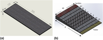
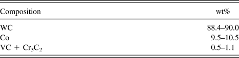
The experiments were performed on a laminate panel of CFRP with dimensions of 100 × 300 × 3 mm [Fig. 1(a)]. The illustration of CFRP panel, which was made using the hand lay-up method, contained eight layers of carbon fibers with 1 layer of tedlar film and layer of synskin, as shown Fig. 1. The orientation of the panel was 0/45° and was subjected to an autoclave process before machining. Details of the work material used are presented in Table I. Two flutes solid uncoated carbide endmills (S2FE-080, Kaizan Solutions, Selangor, Malaysia) with diameters of 8 mm, a helix angle geometry of 30, and length of 60 mm were used in the experiment. The chemical composition of the cutting tool used in the experiment is shown in Table II.
(a) CFRP panel with dimensions and (b) Illustration of the panel's layer.

Workpiece material specification.

Chemical composition of uncoated carbide cutting tool.

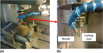
For the chilled air cutting condition, by using compressed air at 0.55 MPa, chilled air was supplied using a vortex tube (VT) with temperature of −10 °C directed on the cutting tool during the machining process. A computer numerical control milling machine (MAZAK VCN-410A, Yamazaki Mazak Corp., Oguchi, Japan) with a spindle power of 7.5 kW and maximum spindle speed of 12,000 rpm was used to machine the CFRP panel in the experiment. Figure 2 shows the setup, and the clamping method which was used to avoid displacement and bending of the CFRP panel during machining.
Machining setup with VT: (a) applying air coolant and (b) close-up view of set-up between nozzle and cutting tool.

B. Tool wear measurement
Tool wear data were recorded for each 100 mm distance traveled, and the images of the tool wear for each distance were captured. The milling operation was aborted and the cutting tool was discarded, when flank wear (V B) or nose wear (V C) reached 0.3 or 0.5 mm respectively (ISO, 1989). A clearer view of the tool wear and machined surface of the CFRP panel after machining was captured using a scanning electron microscope (SEM) when the tool reached the criterion limit for tool life.
III. RESULTS AND DISCUSSION
A. Wear mechanisms of CFRP during high cutting speed
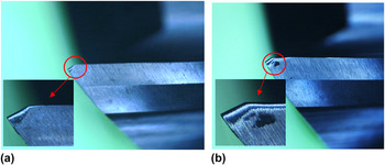
Tool wear is an important aspect which needs to be studied in machining. For this paper the observation is done on V C. Under dry and chilled air machining the growth of the tool wear is steadily increased with the time. However, at primary wear region, the tool wear under chilled air machining is slightly bigger (V C = 0.271 mm) compared to dry machining (V C = 0.202 mm) which can be seen in Fig. 3. It is because with temperature of 100.4 °C under dry machining, the carbon fiber slightly soften which made it easier to be removedReference Nor Khairusshima, Che Hassan, Jaharah, Amin and Md Idriss21 compared to chilled air machining with temperature of 51.2 °C.
Tool wear at initial stage at V = 200 m/min under (a) dry machining at high cutting speed and (b) chilled air machining.

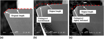
The sharp cutting edge of cutting tool is slowly rounded as the machining reached the steady or secondary wear region. At this stage, either than the tool wear for each cutting condition increase, the contact area between the work material and cutting tool increased, hence the contact stresses is less. The system becomes lightly loaded system and the wear rate is reducing and nearly constant with the increase in sliding distance.Reference Rawat and Attia22 The cutting tool has been worn out during dry and chilled machining as the comparison of the cutting tool before and after dry and chilled machining which can be seen in Fig. 4. Under dry machining, as the tool wear has traveled for approximately 2.91 min, it is clearly seen that the cutting tool has deformed from its original geometry. Compared to chilled air machining, the deformation of cutting tool is observed less compared to dry machining as the cutting tool reached the secondary phase with an approximate machining time of 4.37 min. According to Rawat and Attia,Reference Rawat and Attia22 the temperature increases when machining CFRP which can altere the geometry of the tool and cause the capability of the cutting tool to reduce. Based on Fig. 4, it can be concluded that the wearing out of the tool is related to the cutting temperature. Applying chilled air during machining process reduces the possibility of heat generation, which has the potential to alter the geometry of the tool; and also reduces the wear resistance of the tool.
Cutting tool under different condition (a) new cutting tool, (b) cutting tool under dry machining, and (c) chilled air machining.

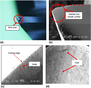
Under tertiary or severe wear region, it was observed that tool wear and tool deformation obviously occurs especially under dry machining. This might be due to the increase of heat generated as the machining continued. The shining area (under microscope) and polished and smooth surface (under SEM) which is found on the cutting tool is due to the abrasive wear.Reference Nor Khairusshima, Che Hassan, Jaharah, Amin and Md Idriss21–Reference Iliescu, Gehin, Gutierrez and Girot23 As the machining continued, the shiny and polished area on the cutting edge became larger (Fig. 5) with larger shiny and polished area is observed under dry machining. The cutting edge of the cutting tool [Fig. 5(b)] has been magnified under SEM as shown in Fig. 5(c). From Fig. 5(c), it can be seen that several voids were observed as a few particles had been pulled out from the cutting tool edge. At higher magnifications, as shown in Fig. 5(d), it can be seen that the black dots, which could be the soft cobalt (Co) binder, had been pulled out during milling to expose the carbide grain.Reference Wang, Kwon, Sturtevant, Kim and Lantrip24 The size of the black holes in Fig. 5(d), was 2.5 µm, which was within the range for the standard size of Co, which is between 1.0 and 3.0 µm (Sandvik, 2005; Sandvik Coromant, Selangor, Malaysia).
SEM picture of tool wear (a) under microscope (b) under SEM (c) on the cutting edge under SEM with magnification of 1300 (d) on the cutting edge under SEM with magnification of 10,000.

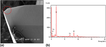
An energy dispersive X-ray (EDX) was performed to identify the element on the tool wear area. Figure 6 shows the results of the tool wear taken under SEM and EDX. Figure 6(a) shows the smooth surface on the wear area under SEM. It has also been reported that this smooth area proved by Iliescu et al.Reference Iliescu, Gehin, Gutierrez and Girot23 is an abrasive wear on uncoated carbide during CFRP machining. The EDX result [Fig. 6(b)] has also confirmed that there was no adhesive wear present on the surface. Rawat and AttiaReference Rawat and Attia22 also observed similar EDX results during the machining of CFRP.
Analysis of tool wear under dry machining (a) SEM picture of tool wear at cutting edge area (b) EDX result for tool wear at cutting edge area.

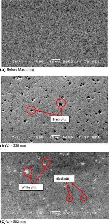
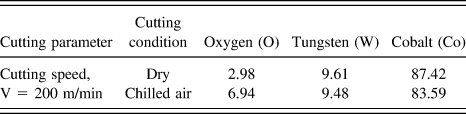
Figure 7 shows the surface of a cutting tool under SEM. Under dry machining, at V C = 520 mm, several small black pits can be found scattered on the surface of the tool. The situation was different under chilled air machining as V C = 502 mm, where fewer black pits were observed on the surface of the cutting tool under the same cutting parameters. The black and white pits on the SEM image of the cutting tool were then analyzed using EDX. Table III summarizes the percentages of the elements found on the surface of the cutting tool under dry and chilled air machining.
SEM image of carbide cutting tool (a) before machining, (b) dry machining, and (c) chilled air machining.

Percentage of element composition on the cutting tool.

Table III shows the percentage of oxygen on the surface of cutting tool, which was found to be less under dry machining compared to under chilled air machining. It is also observed that the quantity of black pits are increased as the quantity of the oxygen decreased. According to Warren et al.,Reference Warren, Nylund and Olefjord25 based on his observation of tungsten oxide, the layer of oxide was reduced as the temperature increased. Thus, the quantity of black pits increased as machining continued under dry machining due to the heat generated. Moreover, white pits appeared at a higher percentage of oxygen which can be found on the surface of cutting tool used for chilled air machining. Many researchers such as Palanikumar and Davim,Reference Palanikumar and Davim26 Campos Rubio et al.,Reference Campos Rubio, José da Silva, Wanderson de Oliveira, Hallak Panzera, Sergio Luiz Moni Ribeiro and Paulo Davim27 and Karnik et al.Reference Karnik, Gaitonde, Campos Rubio, Esteves Correia, Abrão and Paulo Davim28 agreed that more heat is generated as machining continued. However, by applying the chilled air during machining, the cutting temperature can be reduced.Reference Palanikumar and Paulo Davim14,Reference Rawat and Attia22,Reference Gisip, Gazo and Stewart29
IV. CONCLUSIONS
Machining CFRP under dry and chilled air machining was performed to study the wear mechanism during milling CFRP. It is observed that the wear area is found shining and polished because of the excessive wear due to the abrasive nature of carbon which is rubbed continuously at the cutting edge during machining. Because the effectiveness of chilled air can be observed in tertiary stage, thus, at the primary stage, dry machining gives smaller tool wear result compared to the chilled air machining. As the machining continued, the chilled air machining gives a lower tool wear result compared to the dry machining. Under SEM observation on surface of cutting tool, small black pits are scattered on the surface of the tool and EDX detected low percentage of oxygen on the cutting tool surface which is due to heat generated during machining. Meanwhile, under chilled air machining there were several white pitted due to the increase of oxygen percentage as cutting temperature has been reduced.