Introduction
Telemetry tracking and command (TT&C) are two indispensable functions in a satellite system, which provide telemetry data downlink as well as command uplink to track and control the satellite. TT&C antenna usually lies in the S-band (2–2.3 GHz) and requires an omnidirectional coverage in the space, which means the radiation pattern of the TT&C antenna is ideally isotropic with circular polarization. In addition, due to the space resources of microsatellite system are extremely limited, which has brought a great challenge for space-borne antennas, especially in circular polarization radiation, low-profile, broad-beamwidth and roust structure.
Helical antenna is widely applied in aerospace system because of its circular polarization and broadband characteristic. While conventional cylindrical helix usually needs a ground plane (reflector) and has a small angular range in the axial direction [Reference King and Wong1]. [Reference Kim, Choi and Kim2] it can obtain a broader beamwidth by investigating an inverted-cylindrical reflector [Reference Kim, Choi and Kim2] but it has a complicated feeding circuit network at the same time. A rhomboid plate structure in a large size is employed to broaden beamwidth in [Reference He, Wang, Wang, Quan and Xu3]. In [Reference Nakano, Takeda, Honma, Mimaki and Yamauchi4], it introduces a small cylindrical helical antenna with a wide angular region. Additionally, several hemispherical helical antennas are investigated, which can produce pure circular polarization radiation over a broader angular range [Reference Hui, Chan and Yung5–Reference Alsawaha and Safaai-Jazi7]. However, large reflector is still necessary and the antenna structures provided in [Reference Nakano, Takeda, Honma, Mimaki and Yamauchi4–Reference Alsawaha and Safaai-Jazi7] are difficult to maintain stably in vertical direction, which is not suitable for satellite application. Dual-band spiral printed helical antennas proposed in [Reference Han, Hu, Zhao, Gao, Dai, Fu, Zhou and Yuan8] and [Reference Han, Haoliang, Ziwei, Yuchen, Yingjie, Kunkun, Yuan, Zhipeng and Yuan9] are miniaturized by surface and inner dielectric loading, they have extremely low profiles and strong structures while it needs two feeding lines or a feed network simultaneously. Bifilar backfire antenna is first demonstrated by Patton [Reference Patton10] and it has an advantage over a conventional helix in that a ground is not needed. In order to decrease the back lobe levels, tapered feed backfire antenna is proposed in [Reference Yamauchi, Nakano and Mimaki11] and [Reference Nakano, Iio and Yamauchi12]. Moreover, non-resonant length element is also obtained by replacing the end short termination [Reference Keen, Smith and Lee13, Reference Yamauchi, Nakano and Iio14]. Nonetheless, height of the antenna is reminded fairly high, which might influence the field-view of lens in the microsatellite system. Furthermore, it does not recommend using lumped components in space-borne antennas due to the high and low temperature environment.
The work is aimed at exploring a novel backfire helical antenna used as TT&C antenna in microsatellite system (2–2.3 GHz). Attention is focused on introducing a new structural design to realize low profile and broad beamwidth. In this paper, we present a compact design of a two-arm backfire tapered cone helical antenna. It has a strong structure with low profile and outstanding circular polarization radiation over a wide angular. These characteristics make it an attractive candidate for TT&C application in microsatellite system. A prototype of the antenna is constructed and its radiation characteristics are experimentally tested in this paper.
Antenna design geometry description
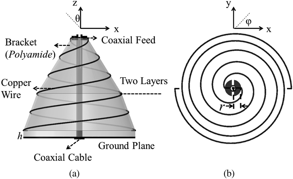
Figure 1 shows the configuration of the antenna. The thin helical wire is wound on a two-layer stacked tapered cone surface. The geometry of the wire per layer in a rectangular coordinate system can be described by the following equations:


where r is the upper radius of cone, θ is the cone taper angle, n is the number of turns of the helix per layer and the pitch is s.
Antenna geometry of the two-arm backfire two-layer tapered cone antenna (a) front view (b) bottom view.
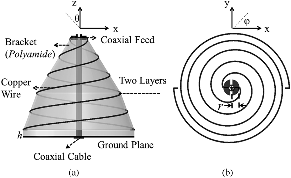
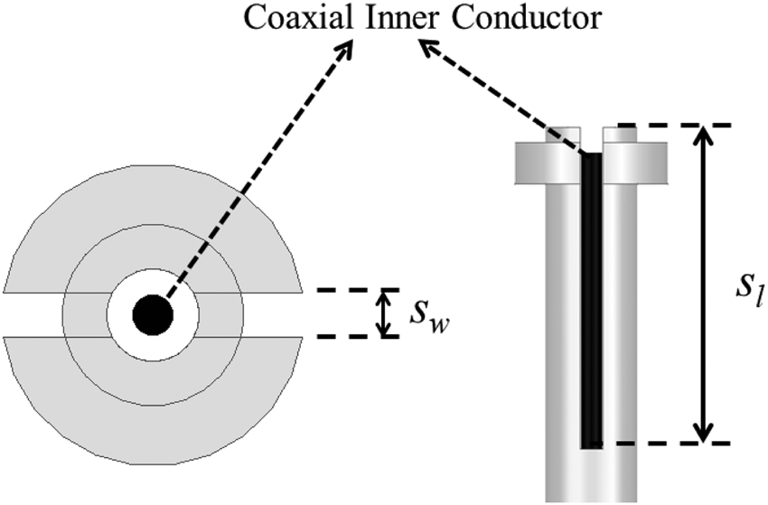
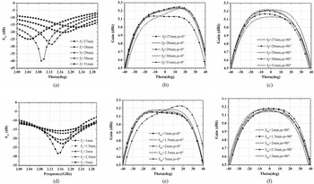
The antenna consists of two tapered sections. The lower radius of the first section is equal to the upper radius of the second section. An inside coaxial bracket supports the whole structure and provides the excitation. Further, as shown in Fig. 2, a split-coaxial balun is introduced for the current cancellation on the outer side of the coaxial line [Reference Makarov and Ludwig15]. Figure 3 shows that both the slot length s l and slot width s w have a minor influence on radiation performance of antenna while have a significant influence on return loss. Accordingly, a good impedance matching can be achieved simply by varying the slot length s l and slot width s w.
Geometry of the matching slot.

Effect of varying slot length s l on (a) return loss (b) φ = 0° radiation patterns (2.1 GHz) (c) φ = 90° radiation patterns (2.1 GHz) and effect of varying slot width s w on (d) return loss (e) φ = 0° radiation patterns (2.1 GHz) (f) φ = 90° radiation patterns (2.1 GHz).

For backfire helical antenna, there are existing two distinct regions [Reference Chen16] and it is possible to acquire desired radiation pattern by tuning the factors n, s and q (ratio of r to s) carefully [Reference Kilgus17]. Firstly, the helix wound on the upper tapered section plays the main role for radiating. ΔC (change circumference per turn) is selected around λ to keep phase congruence among helix and a small n could realize a circular polarization wave. A fairly wide beamwidth can be achieved by s ≈ 0.25λ and q ≈ 0.22. Secondly, the lower tapered section makes contributions to the attenuation of current. The current distribution largely determines the operation of a wire antenna [Reference Nakano, Okuzawa, Ohishi, Mimaki and Yamauchi18]. A reflected current traveling backwards from the open end towards the feed point would damage the purity of circular polarization radiation and it would decrease when the wire length l is an integral multiple of λ. In particular, compared with the uniform structure, the tapered one needs fewer helical turns to reach the same l, which means a lower profile. The key parameters of antenna can be calculated as follows:


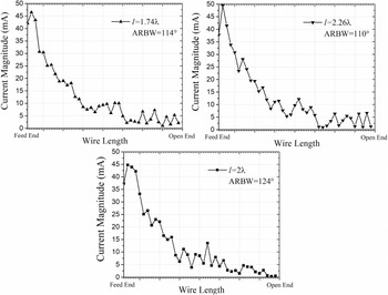
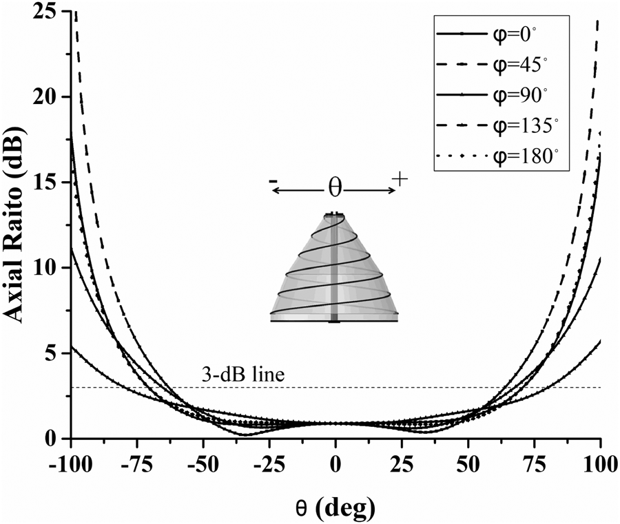
Figure 4 illustrates the current distribution and 3-dB axial ratio beamwidth (ARBW) of a two-half turn backfire-tapered cone helical antenna at three wire lengths of l/λ = 1.74, l/λ = 2 and l/λ = 2.26. It can be seen that except for the case with l/λ = 2, the current distributions of the other two cases show the existence of a reflected current wave. For the case with l/λ = 2, smoothly decaying-traveling current way along the antenna wire can be seen and it has the widest 3-dB ARBW. Furthermore, in Fig. 5 the simulated axial ratio is also depicted. A very wide circular polarization angular coverage (axial ratio ≤3 dB) of 124°and a quite low axial ratio of 0.86 dB are obtained with l/λ = 2 at center frequency 2.1 GHz. Therefore, the decreased reflected current improves the circular polarization of antenna.
Current distribution and ARBW of a two half- turn backfire tapered cone helical antenna with ΔC/λ ≈ 1, s/λ ≈ 1/4, q ≈ 0.22, n up = 1.5, n down = 1, h = 6 mm and different wire lengths at center frequency 2.1 GHz.

Simulated axial ratio at center frequency 2.1 GHz.

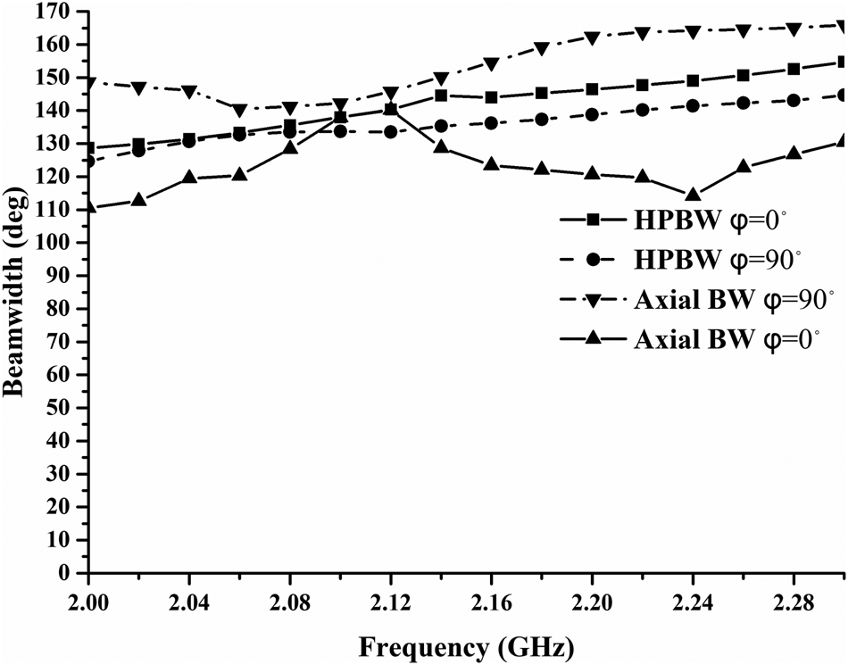
Figure 6 displays variations of antenna beamwidth at φ = 0° (x–z plane) and φ = 90° (y–z plane). The dimensions of the two-half turn backfire-tapered cone helical antenna are l/λ = 2, ΔC/λ ≈ 1, s/λ ≈ 1/4, q ≈ 0.22 and h = 6 mm. The 3-dB ARBW and the half power beamwidth (HPBW), varies between 110° and 165°, 125° and 155°, respectively. In other words, it has a very wide beamwidth within the frequency band. The maximum HPBW difference between the beamwidths of two different planes is less than 10°, which means the radiation pattern of the antenna is highly symmetric about the z-axis in a wide frequency band of 2–2.3 GHz. The normalized power patterns versus frequency at φ = 0°and φ = 90°are also presented in Fig. 7. Closer examinations of these patterns figures out that each has a broad main beam and pattern shape remains constant within the focused frequency TT&C band. It is noted that the HPBW increases as the frequency increases. It indicates that the beam is broadened, which is the desired characteristic for TT&C application.
Simulated HPBW and 3-dB axial beamwidth (ARBW) versus frequency at φ = 0° and φ = 90°.

Simulated normalized power patterns at φ = 0° and φ = 90° for the two half- turn backfire tapered cone helical antenna of Fig. 4.

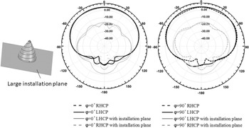
The installation platform has a very significant impact on the directivity of the antenna and the influence could be reduced by reducing back lobe level of antenna. In this work the front-to-back ratio is more than 18 dB over S band and Fig. 8 shows the normalized power patterns of antenna with a large installation plane below, which represents the surface of satellite. It demonstrates that the large surface of satellite has a slight impact on radiation patterns of the proposed antenna. Further simulations of radiation performance should be done for specific installation platforms case by case.
Normalized power patterns at 2.1 GHz of proposed antenna with a large installation plane below, which represents the surface of satellite.

Simulation and measured result
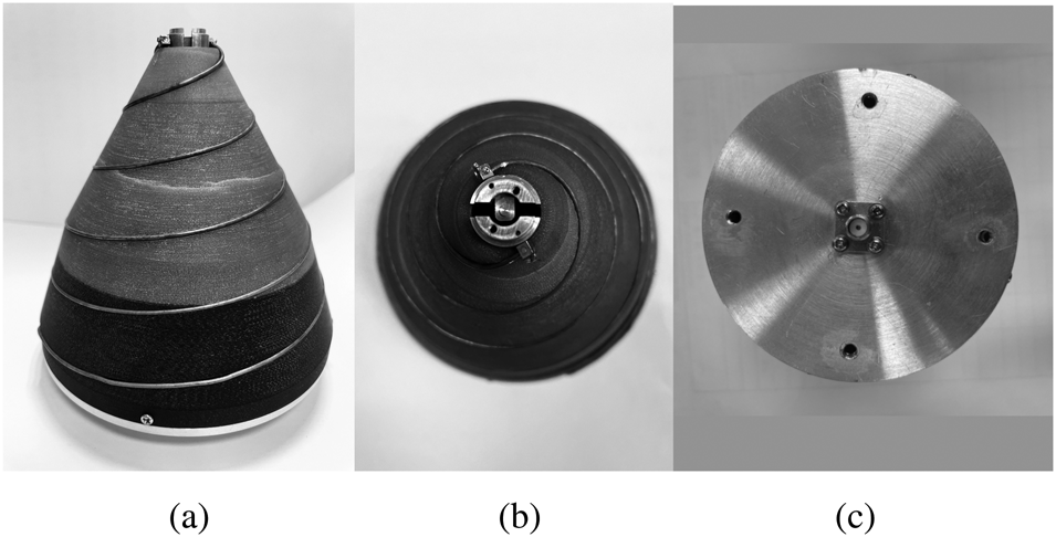
Figure 9 shows a picture of the prototype proposed in last section. The total number of helical turns is only 2.5 and the height is just 89 mm. It has left-hand circular polarization radiation with s = 34.2 mm, ΔC = 140.1 mm, q = 0.22 and θ = 14°. Compared with a conventional helical antenna working at the same frequency, the proposed antenna has a substantial decrease of 67% in its height. Finally, there are four mounting holes on the reflector for installation and a 50 Ω SMA coaxial connector is attached to the reflector. After the prototype was carefully constructed, the measurement results of far-field patterns, axial ratio, VSWR and gain are presented and compared with the corresponding simulation results.
View of the manufactured antenna (a) side view (b) front view (c) bottom view.

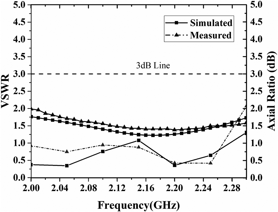
Comparisons of the simulated and measured VSWR versus frequency, as well as the axial ratio, for the fabricated prototype are shown in Fig. 10. There are generally good agreements between the simulated and measured VSWR and axial ratio results. The experimental VSWR ≤2 and axial ratio ≤3 dB covers the frequency band from 2 to 2.3 GHz. Moreover, the measured 3-dB axial ratio bandwidth is 18.8% relative to a mid-band frequency of 2.12 GHz, which clearly indicate that the proposed antenna can radiate effectively over entire TT&C bandwidth.
Comparison of simulated and measured VSWR versus frequency, as well as the axial ratio, for the two-half turn backfire tapered cone helical shown in Fig. 9.

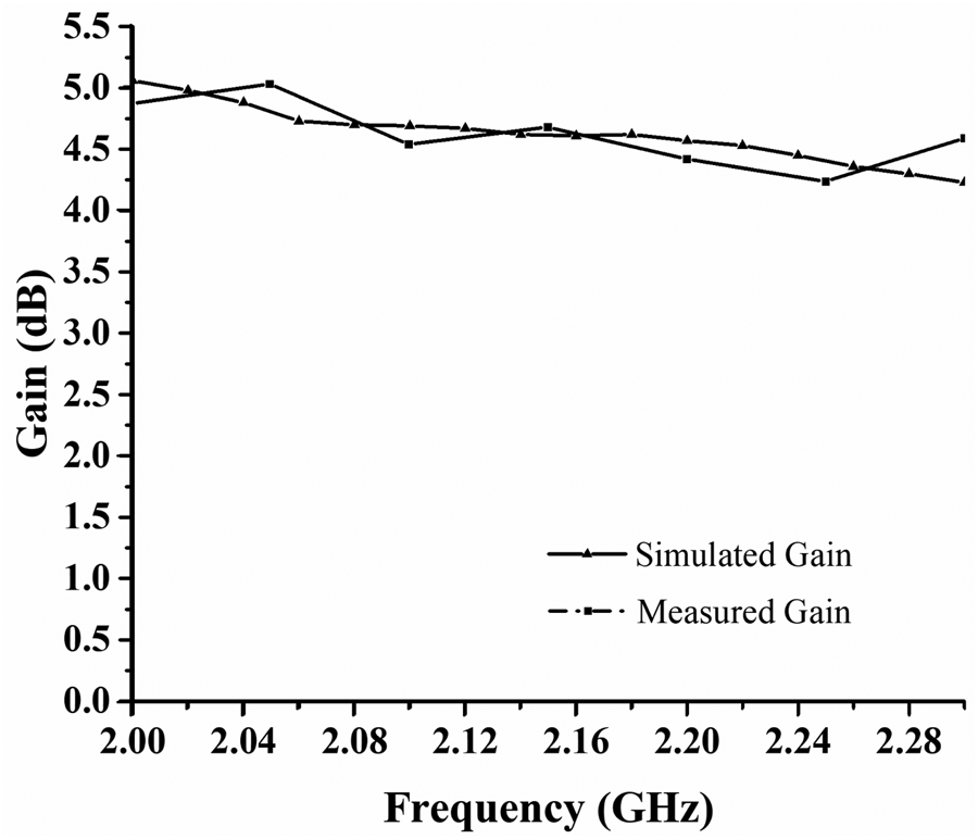
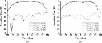
Far-field patterns of the prototype antenna are also examined. Variations of the simulated and measured gain versus frequency are shown in Fig. 11. Again, a good agreement between the measured and calculated results is noted. The maximum measured gain is about 5 dBi with about ±1 dB fluctuations. Figure 12 illustrates measured and simulated normalized radiation patterns of the prototype antenna at 2.1 GHz. A closer examination of these patterns emphasizes good agreements between measured and simulated results and also ascertains the axial symmetry of the main beam. The radiation patterns consist of a large main lobe with almost no sidelobes. The measured half-power beamwidths are around 132°at φ = 0°and 141° at φ = 90°, while the corresponding simulated beamwidth are more than 131°at φ = 0°and 143° at φ = 90°. Such a wide beamwidth clearly indicates that the proposed antenna can provide efficient radiation over a broad angular range, which is suitable for TT&C application in satellites.
Variations of gain versus frequency for the two half- turn backfire tapered cone helical antenna of Fig. 9.

Calculated and measured normalized radiation patterns for the two-half turn backfire tapered cone helical shown in Fig. 9 (a) φ = 0° (b) φ = 90°.

Moreover, thermal vacuum-cycle test (−90 to 90°C) and mechanical experiments were both carried out for the fabricated antenna, which verified the antenna reliability well for microsatellites.
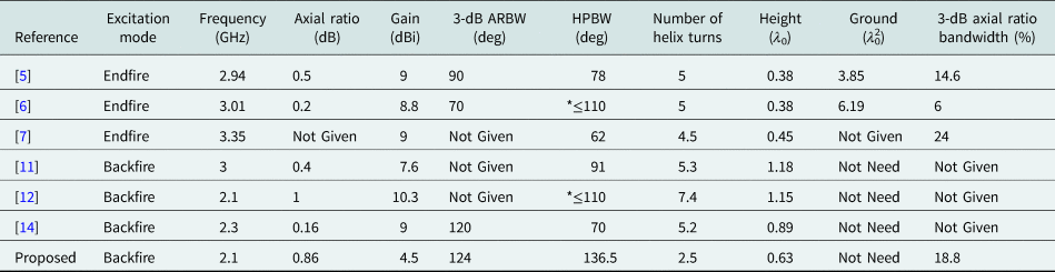
Table 1 compares the performance of the proposed antenna with some reports mentioned before. Compared with the endfire structures [Reference Hui, Chan and Yung5–Reference Alsawaha and Safaai-Jazi7], the proposed antenna is easier for impedance matching and more solid to maintain an erect structure in a satellite system. The large ground plane is unnecessary. Meanwhile, it has the fewest helical turns and lowest profile among the backfire structures [Reference Yamauchi, Nakano and Mimaki11, Reference Nakano, Iio and Yamauchi12] and [Reference Yamauchi, Nakano and Iio14]. Moreover, it has a wider HPBW and 3-dB APBW than all aforementioned designs simultaneously.
Comparisons of proposed and reference antennas

Conclusion
A low-profile two-arm backfire tapered cone helical antenna is carefully studied both theoretically and experimentally. Compared with a conventional helical antenna working at the same frequency, this new design incorporates two major modifications, including the replacement of the uniform section with two tapered cone sections, which lead to a dramatic decrease of 67% in its height and an increase both in HBPW and 3-dB ARBW, and a matching section consists of a split-coaxial balun, which makes it easy to realize good impedance matching. It provides a robust and low-profile structure with a more than 124° angular coverage of circular polarization radiation, a HPBW of more than 125°, a maximum gain of 5.1 dBi, a 3-dB axial ratio bandwidth of 18.8% and nearly equal E- and H- plane far-field patterns with high degree of axial symmetry from 2 to 2.3 GHz. The low profile and excellent circular polarization radiation make it an excellent candidate for TT&C application in the microsatellite system.
Acknowledgements
This work was supported by the National Natural Science Foundation of China under contract 61671304 and the project of Key technical personnel of Chinese Academy of Sciences.
Conflict of interest
The authors report no conflict of interest.
 Zhanyu Kang was born in Ganzhou, Jiangxi Province, China, in 1991. She received the B.S. and M.S. degrees in electronic engineering from University of Electronic Science and Technology of China (UESTC), Chengdu, China in 2009 and 2013 respectively, and is currently working as antenna design engineer in Innovation Academy for Microsatellites, Chinese Academy of Sciences. Her research interests include Microwave Devices, Phase Array Antenna and Satellite Antenna.
 Lianxing He was born in Lianyun, China. He received the M.S. and Ph.D. from Shanghai Institute of Ceramics, Chinese Academy of Sciences (CAS) in 1997 and 2000, respectively. Currently he is working as a Research Fellow in Innovation Academy for Microsatellites of CAS and also an adjunct Professor in Shanghai Tech University.
 Dongliang Fei was born in Nantong, Jiangsu Province, China, in 1990. He received the B.S and M.S degrees in Xidian University, Xi'an, China in 2009 and 2013 respectively, and is currently working as antenna design engineer in Innovation Academy for Microsatellites, Chinese Academy of Sciences. His research interests include Satellite antenna and Phase array antenna.
 Mingkang Li received M.S. degree from University of Science and Technology of China, Hefei, China, in 2017. From 2017 to 2021, he was a microwave engineer with Huawei Technologies Co Ltd., and was engaged in research on filters and antennas of 5G base-stations in sub-6 GHz and mm-wave frequency bands. He is currently an engineer for Innovation Academy for Microsatellites, Chinese Academy of Sciences, where he has been engaged in the development of antennas for satellite communications.
 Guang Liang received a degree in electronic information science and technology from Xiamen University in 2005 and received his doctor degree in communication information system from CAS in 2010. His main research interests include phased array antenna and satellite communication.