1 Introduction
The maximal spreading that an impacting drop can attain is of considerable importance in a variety of natural processes and industrial applications, e.g. raindrop impact on soil (Joung & Buie Reference Joung and Buie2014), inkjet printing (Derby Reference Derby2010), fuel spray (Moreira, Moita & Panao Reference Moreira, Moita and Panao2010), bloodstains in crime scenes (Laan et al.
Reference Laan, Bruin, Bartolo, Josserand and Bonn2014) and wing anti-ice (Mishchenko et al.
Reference Mishchenko, Hatton, Bahadur, Taylor, Krupenkin and Aizenberg2010). In the case of a high impact velocity
 $V$
, the spreading dynamics of the drop is primarily dominated by the competition among inertia, surface tension and viscous dissipation. Therefore, two dimensionless parameters are usually used to describe the spreading process: the Reynolds number
 $Re$
(
 $=\unicode[STIX]{x1D70C}VD_{0}/\unicode[STIX]{x1D707}$
) and the Weber number
 $We$
(
 $=\unicode[STIX]{x1D70C}V^{2}D_{0}/\unicode[STIX]{x1D70E}$
), where
 $\unicode[STIX]{x1D70C}$
,
 $\unicode[STIX]{x1D707}$
,
 $\unicode[STIX]{x1D70E}$
and
 $D_{0}$
are the density, viscosity, surface tension coefficient and diameter of the drop, respectively. For drops with relatively low impact velocity, one may also need to take account of the wettability of the substrate, which determines the drop shape at the equilibrium state.
Several models have been proposed to correlate the maximal spreading ratio
 $\unicode[STIX]{x1D6FD}_{max}$
(
 $=D_{max}/D_{0}$
) with the Weber and Reynolds numbers, based on the conservation of energy or momentum, where
 $D_{max}$
is the maximal spreading diameter. For very viscous drops, the kinetic energy of the drop is supposed to be mainly consumed by viscous dissipation. If further taking volume conservation into account, one can obtain a scaling law:
 $\unicode[STIX]{x1D6FD}_{max}\sim Re^{1/5}$
(Chandra & Avedisian Reference Chandra and Avedisian1991). In the limit of low viscosity, assuming that all the kinetic energy is transformed into surface energy at the maximal spreading, one can obtain another scaling law:
 $\unicode[STIX]{x1D6FD}_{max}\sim We^{1/2}$
(Collings et al.
Reference Collings, Markworth, Mccoy and Saunder1991). However, Clanet et al. (Reference Clanet, Béguin, Richard and Quéué2004) pointed out that this scaling law overestimates the maximal spreading ratio for low-viscosity liquids of practical interest, e.g. water, due to the fact that there still exists visible fluid motion inside the drop at maximal spreading. They proposed a scaling law
 $\unicode[STIX]{x1D6FD}_{max}\sim We^{1/4}$
based on momentum conservation, which agrees well with their experimental observations. Wildeman et al. (Reference Wildeman, Visser, Sun and Lohse2016) numerically found that approximately one-half of the kinetic energy was transformed into surface energy, independent of the impact parameters and the energy loss mechanisms. Laan et al. (Reference Laan, Bruin, Bartolo, Josserand and Bonn2014) proposed an interpolation solution that allows a smooth cross-over between the two scaling laws of
 $We^{1/2}$
and
 $Re^{1/5}$
. Lee et al. (Reference Lee, Laan, De Bruin, Skantzaris, Shahidzadeh, Derome, Carmeliet and Bonn2016) extended the Laan approach by taking account of the wettability, and achieved a universal rescaling of the maximal spreading ratio for impacting pure drops,
 $$\begin{eqnarray}\unicode[STIX]{x1D6FD}_{max}^{2}=\left(\frac{We^{1/2}Re^{1/5}}{A+We^{1/2}}\right)^{2}+\unicode[STIX]{x1D6FD}_{0}^{2},\end{eqnarray}$$
where
 $\unicode[STIX]{x1D6FD}_{0}=D_{\unicode[STIX]{x1D703}}/D_{0}$
, and
 $D_{\unicode[STIX]{x1D703}}$
denotes the maximal drop diameter at the equilibrium state with a contact angle
 $\unicode[STIX]{x1D703}$
;
 $A$
is a constant obtained by data fitting. This model was shown to be in good agreement with experimental data for a wide range of impact velocities (
 $We\sim 1{-}1000$
) (Lee et al.
Reference Lee, Laan, De Bruin, Skantzaris, Shahidzadeh, Derome, Carmeliet and Bonn2016).
Compared with pure drops, impact of compound drops has not been extensively studied. The dynamics of Leidenfrost compound drops impacting on an oblique plate was investigated experimentally, including bouncing and pinch-off (Chiu & Lin Reference Chiu and Lin2005) and resident time (Chen, Chiu & Lin Reference Chen, Chiu and Lin2007). The occurrence of a counter jet inside the drop was experimentally identified in the impact of a hollow drop (Gulyaev & Solonenko Reference Gulyaev and Solonenko2013), of which the dynamics and heat transfer were further investigated numerically by Li et al. (Reference Li, Duan, Zheng and Liu2018). Tasoglu et al. (Reference Tasoglu, Kaynak, Szer, Demirci and Muradoglu2010) numerically studied the deformation of the inner droplet inside the compound drop at small
 $We$
and
 $Re$
(
 ${\sim}1$
). Here, we will focus on the maximal spreading of an impacting compound drop, which is relevant to practical applications such as bioprinting (Murphy & Atala Reference Murphy and Atala2014; Hendriks et al.
Reference Hendriks, Visser, Henke, Leijten, Saris, Sun, Lohse and Karperien2015) and drug delivery (Delcea, Mohwald & Skirtach Reference Delcea, Mohwald and Skirtach2011). In particular, it remains unclear how the presence of the inner droplet affects the spreading dynamics and the maximal spreading ratio.
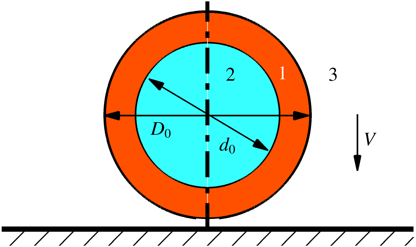
A compound drop impacts onto a horizontal wall at a vertical velocity
 $V$
. Initially, the surrounding gas is still, and the diameters of the outer phase (liquid 1) and inner phase (liquid 2) of the compound drop are
 $D_{0}$
and
 $d_{0}$
, respectively.

In this paper, we numerically investigate the maximal spreading ratio of an impacting compound drop at moderate Reynolds and Weber numbers (
 $Re=1000$
and
 $10\leqslant We\leqslant 800$
). For this purpose, a ternary-fluid diffuse-interface method is adopted in our axisymmetric simulations (Zhang et al.
Reference Zhang, Ding, Gao and Wu2016). We examine the effects of the volume fraction of the inner droplet and the surface tension ratio on the flow features of impact dynamics and the maximal spreading of the compound drop. Our aim is to seek a universal scaling law for the maximal spreading ratio of the compound drops, similar to the one for pure drops, i.e. (1.1).
2 Methodology
We consider numerical simulations of a compound drop impacting on a flat wall. A sketch of the flow problem is shown in figure 1, in which the inner and outer interfaces of the compound drop are initially set in a concentric manner, with
 $d_{0}$
and
 $D_{0}$
the diameters, respectively. We use a ternary-fluid diffuse-interface method, which allows us to simulate ternary-fluid flows in the presence of moving contact lines (Zhang et al.
Reference Zhang, Ding, Gao and Wu2016). The interfaces are represented by the contours of the volume fractions of the fluids 1 and 2, i.e.
 $C_{1}$
and
 $C_{2}$
respectively. The interface evolution can be tracked by
 $$\begin{eqnarray}\frac{\unicode[STIX]{x2202}\boldsymbol{C}}{\unicode[STIX]{x2202}t}+\unicode[STIX]{x1D735}\boldsymbol{\cdot }(\boldsymbol{u}\boldsymbol{C})=\frac{1}{Pe}\unicode[STIX]{x1D6FB}^{2}\unicode[STIX]{x1D733},\end{eqnarray}$$
where
 $\boldsymbol{C}=(C_{1},C_{2})$
and
 $\boldsymbol{u}$
is the flow velocity. The chemical potential
 $\unicode[STIX]{x1D733}=(\unicode[STIX]{x1D6F9}_{1},\unicode[STIX]{x1D6F9}_{2})$
is defined as
 $$\begin{eqnarray}\unicode[STIX]{x1D6F9}_{i}=C_{i}^{3}-1.5C_{i}^{2}+0.5C_{i}-C_{1}C_{2}(1-C_{1}-C_{2})-Cn^{2}\unicode[STIX]{x1D6FB}^{2}C_{i},\quad i=1\text{ or }2,\end{eqnarray}$$
where the Cahn number is set to
 $Cn=0.75h/D_{0}$
, the Péclet number is set to
 $Pe=1/Cn$
(Liu & Ding Reference Liu and Ding2015) and
 $h$
is the mesh size. Accordingly, the averaged density and viscosity can be calculated by
 $\unicode[STIX]{x1D70C}=\unicode[STIX]{x1D6F4}\unicode[STIX]{x1D70C}_{i}C_{i}$
and
 $\unicode[STIX]{x1D707}=\unicode[STIX]{x1D6F4}\unicode[STIX]{x1D707}_{i}C_{i}$
, where the subscript
 $i$
(
 $=1$
, 2 and 3) denotes the respective fluid.
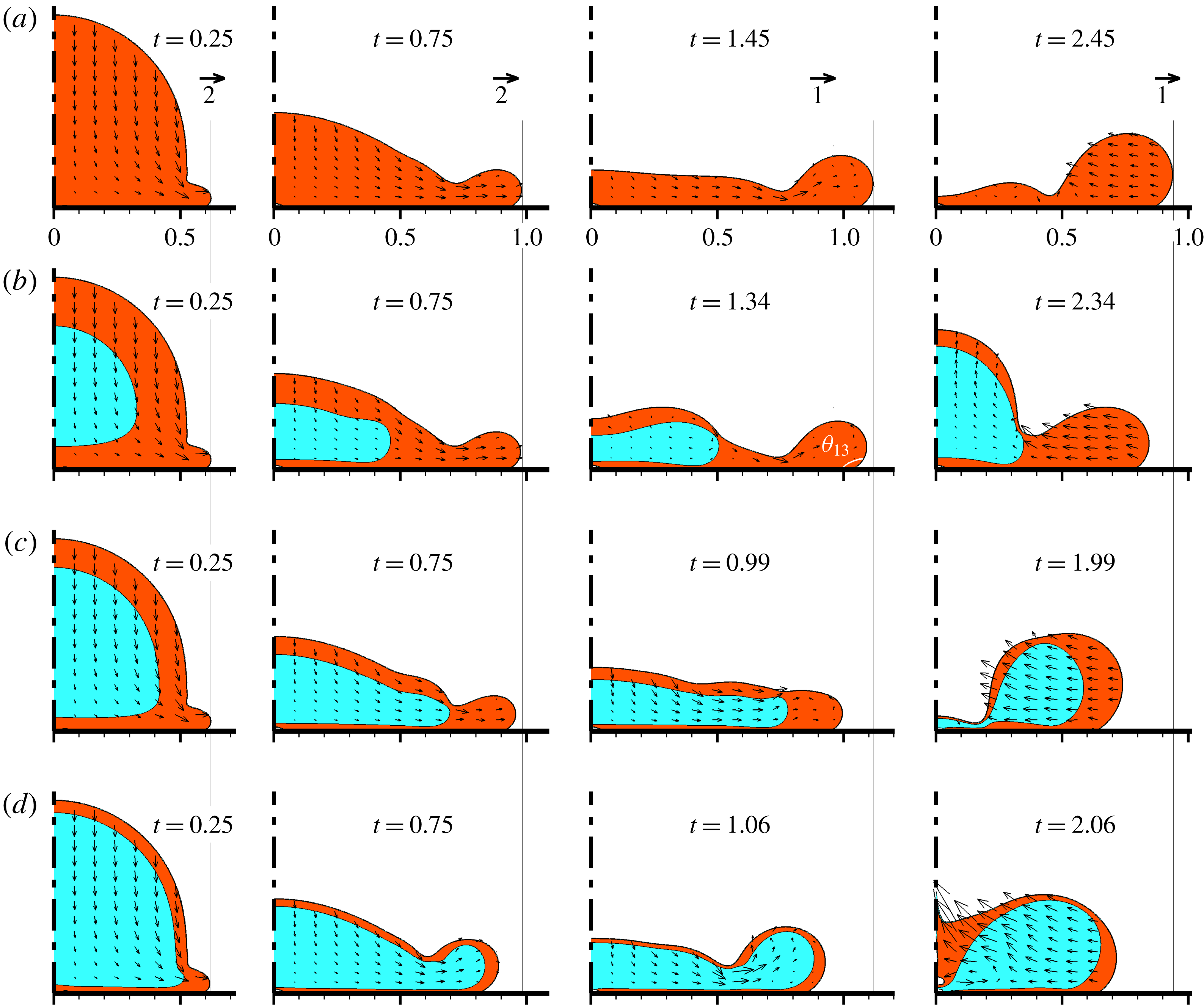
Snapshots of an impacting compound drop at
 $\unicode[STIX]{x1D6FE}=1$
,
 $We=50$
and various volume fractions:
 $\unicode[STIX]{x1D6FC}=0$
(a), 0.216 (b), 0.450 (c) and 0.729 (d). The columns from left to right correspond to different times:
 $t=0.25$
, 0.75,
 $t_{max}$
and
 $t_{max}+1.0$
, respectively. Here,
 $t_{max}$
denotes the time at the maximal spreading of the compound drop. The reference velocity vectors are provided in (a); note that the same one is used in each column.

We assume that the surface tension coefficients among the ternary fluids, i.e.
 $\unicode[STIX]{x1D70E}_{13}$
,
 $\unicode[STIX]{x1D70E}_{12}$
and
 $\unicode[STIX]{x1D70E}_{23}$
, are well balanced such that the summation of any two of them is larger than the third one. Here,
 $\unicode[STIX]{x1D70E}_{ij}$
denotes the surface tension coefficient between fluids
 $i$
and
 $j$
. The wetting condition is mainly prescribed by the contact angle
 $\unicode[STIX]{x1D703}_{13}$
, i.e. the angle that the interface between the fluids 1 and 3 intersects with the substrate (see the third panel in figure 2
b). Similarly, we can have the definition of
 $\unicode[STIX]{x1D703}_{23}$
and
 $\unicode[STIX]{x1D703}_{12}$
, which are set to
 $90^{\circ }$
and
 $150^{\circ }$
respectively. Given
 $\unicode[STIX]{x1D70E}_{13}$
,
 $\unicode[STIX]{x1D70E}_{12}$
,
 $\unicode[STIX]{x1D703}_{12}$
,
 $\unicode[STIX]{x1D703}_{13}$
and
 $\unicode[STIX]{x1D703}_{23}$
, the surface tension coefficient
 $\unicode[STIX]{x1D70E}_{23}$
can be uniquely determined (Zhang et al.
Reference Zhang, Ding, Gao and Wu2016). Note that only the interface between fluids 1 and 3 is in contact with the substrate during the spreading of the compound drop (see e.g. figures 2 and 3); therefore,
 $\unicode[STIX]{x1D703}_{23}$
and
 $\unicode[STIX]{x1D703}_{12}$
are in principle irrelevant for the maximal spreading. More details on the numerical implementation can be found in Zhang et al. (Reference Zhang, Ding, Gao and Wu2016). The flow properties of the fluid 1 and
 $\unicode[STIX]{x1D70E}_{13}$
are chosen to define the dimensionless parameters:
 $We=\unicode[STIX]{x1D70C}_{1}V^{2}D_{0}/\unicode[STIX]{x1D70E}_{13}$
and
 $Re=\unicode[STIX]{x1D70C}_{1}VD_{0}/\unicode[STIX]{x1D707}_{1}$
. The volume fraction of the inner droplet
 $\unicode[STIX]{x1D6FC}$
and the surface tension ratio
 $\unicode[STIX]{x1D6FE}$
are defined as follows:
 $\unicode[STIX]{x1D6FC}=(d_{0}/D_{0})^{3}$
and
 $\unicode[STIX]{x1D6FE}=\unicode[STIX]{x1D70E}_{12}/\unicode[STIX]{x1D70E}_{13}$
. In this study, we set
 $\unicode[STIX]{x1D70C}_{2}/\unicode[STIX]{x1D70C}_{1}=1$
,
 $\unicode[STIX]{x1D70C}_{3}/\unicode[STIX]{x1D70C}_{1}=0.001$
,
 $\unicode[STIX]{x1D707}_{2}/\unicode[STIX]{x1D707}_{1}=1$
and
 $\unicode[STIX]{x1D707}_{3}/\unicode[STIX]{x1D707}_{1}=0.025$
. Therefore, the fluid 3 is essentially a gas phase.
The method has been quantitatively verified previously by the comparison of the drop shape at equilibrium with the analytical solutions (Zhang et al.
Reference Zhang, Ding, Gao and Wu2016), for example, for the compound drops resting either on a wall or inside a capillary. In addition, we simulate the impact dynamics of compound drops at
 $\unicode[STIX]{x1D70E}_{23}=0$
, and the numerical results of maximal spreading ratio compare favourably with (1.1) (see figure 4
b). This also partly verifies the method in the simulation of impacting compound drops. In all of the calculations reported here, the impact of the compound drop is simulated in a domain of
 $2D_{0}\times 1.2D_{0}$
on a uniform Cartesian mesh. We have checked that the numerical results converged with mesh refinement (
 $h=0.002D_{0}$
,
 $0.001D_{0}$
and
 $0.00067D_{0}$
), and thus choose
 $h=0.001D_{0}$
in the present study.
3 Results and discussion
Unless otherwise stated, the Reynolds number and contact angle are fixed:
 $Re=1000$
and
 $\unicode[STIX]{x1D703}_{13}=150^{\circ }$
, all the times are made dimensionless by the time scale
 $D_{0}/V$
, and the inner (outer) interface is represented by the contour of
 $C_{2}=0.5$
(
 $C_{1}=0.5$
). Note that in the present numerical set-up, the compound drop with either
 $\unicode[STIX]{x1D6FC}=0$
or
 $\unicode[STIX]{x1D6FE}=0$
is equivalent to a pure drop.
3.1 Interaction between the inner and outer interfaces
Once in contact with the substrate, the impacting compound drop immediately spreads on it; at the same time, the inner droplet is squeezed vertically by the surrounding liquid, and becomes flattened at its top and bottom. The deformation of the inner droplet is determined by the interaction between the inner and outer interfaces, and could in turn affect the spreading and retraction of the compound drop. Clearly, the deformability of the inner interface relative to the outer one is characterized by two parameters: the volume fraction of the inner droplet
 $\unicode[STIX]{x1D6FC}$
and the surface tension ratio
 $\unicode[STIX]{x1D6FE}$
. In order to assess the effect of the deformability of the inner droplet on the impact dynamics, we perform a series of numerical experiments with varied
 $\unicode[STIX]{x1D6FC}$
or
 $\unicode[STIX]{x1D6FE}$
.
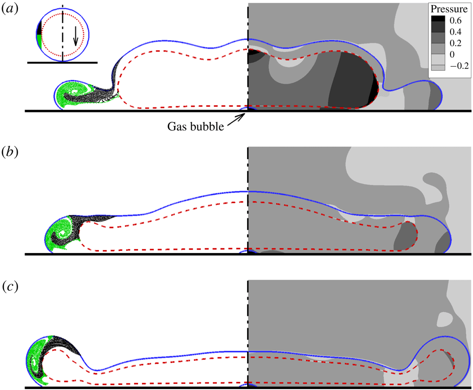
Snapshots of impacting compound drops at the maximal spreading with
 $\unicode[STIX]{x1D6FC}=0.512$
,
 $We=50$
and various
 $\unicode[STIX]{x1D6FE}$
, with respect to visualization particles (left) and pressure contours (right). In particular, (a)
 $\unicode[STIX]{x1D6FE}=4$
and
 $t=0.86$
, (b)
 $\unicode[STIX]{x1D6FE}=1$
and
 $t=0.92$
, and (c)
 $\unicode[STIX]{x1D6FE}=0.25$
and
 $t=1.32$
. In (a), the upper-left corner shows the initial position of the visualization particles.

Figure 2 shows the snapshots of the impacting compound drop at
 $We=50$
, with different volume fractions (
 $\unicode[STIX]{x1D6FC}=0$
, 0.216, 0.450 and 0.729) and a fixed surface tension ratio (
 $\unicode[STIX]{x1D6FE}=1$
). At the early stage of drop impact (
 $t\leqslant 0.25$
), the presence of the inner droplet seems to have no effect on the spreading with respect to the shape and wetted area of the compound drop, primarily because of the generally insignificant deformation of the inner droplet. When a rim occurs at the spreading front (
 $t=0.75$
), the subsequent evolution of the inner and outer interfaces is seen to follow two distinct scenarios, based on which two flow regimes can be defined respectively. At the relatively large
 $\unicode[STIX]{x1D6FC}$
(
 $=0.729$
), the inner droplet participates in the rim formation. In particular, the liquid is continuously pumped from the inner droplet into the rim, in a manner that the evolution of the inner interface is apparently synchronized with the outer one (figure 2
d). This flow regime shall be referred to as joint rim formation hereafter. In this regime, the presence of inner interface in the rim introduces additional surface tension force to resist the outward motion of the rim, thereby significantly slowing down the spreading speed of the compound drop. At the relatively low
 $\unicode[STIX]{x1D6FC}$
(e.g.
 $\unicode[STIX]{x1D6FC}=0.216$
), the inner droplet gradually evolves into a ‘pancake’ (
 $t=0.75$
, the second panel in figure 2
b), but does not enter the rim. Instead, it blocks the liquid supply to the rim, making the maximal spreading diameter slightly smaller than that of the pure drop (
 $t=1.34$
, the third panel in figure 2
b). This flow regime is referred to as jammed spreading hereafter. We note that only the outer liquid (i.e. the fluid 1) is in contact with the substrate during the spreading of the compound drop. The inner liquid (i.e. the fluid 2) may come into contact with the substrate during the retraction of the compound drop (see the last panel in figures 2
c and 2
d).
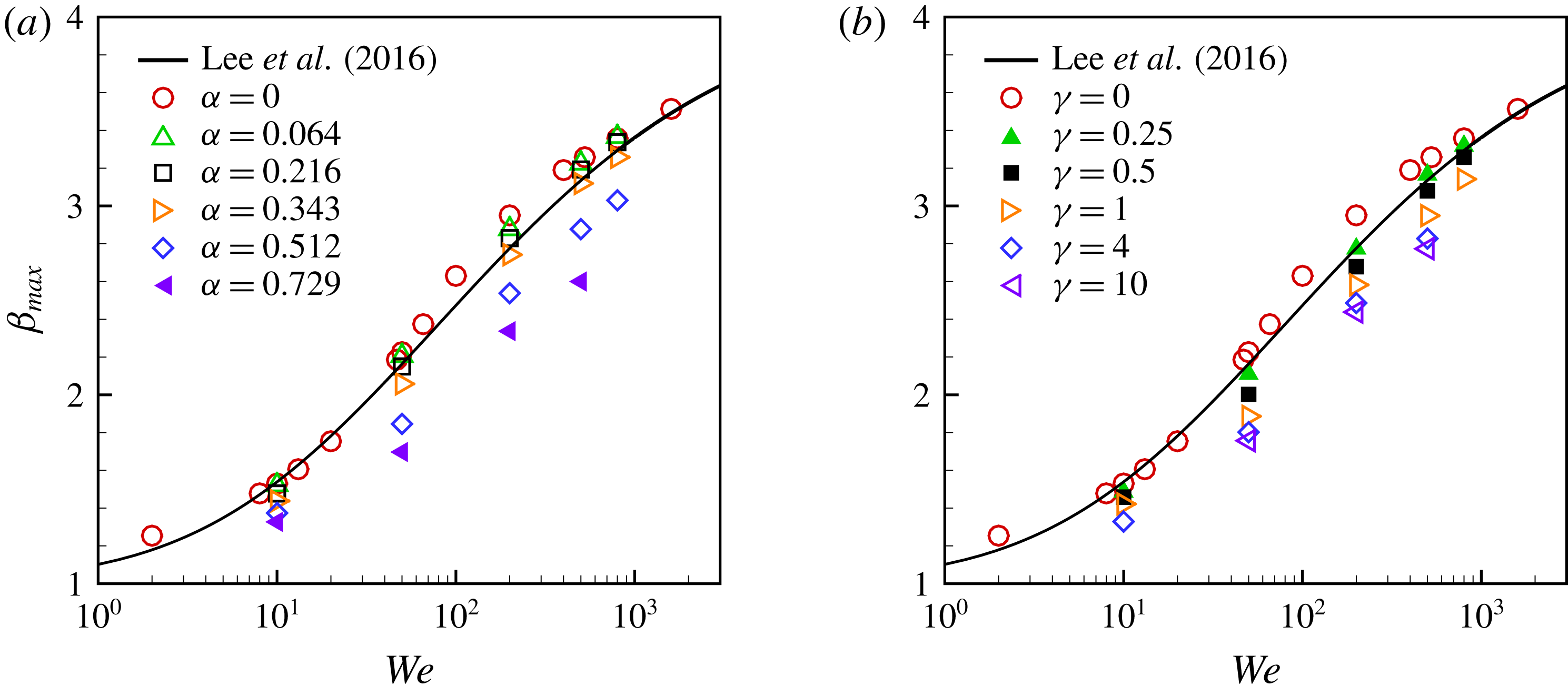
Maximal spreading ratio
 $\unicode[STIX]{x1D6FD}_{max}$
as a function of
 $We$
with: (a) a fixed
 $\unicode[STIX]{x1D6FE}$
(
 $=2$
) and varied
 $\unicode[STIX]{x1D6FC}$
, and (b) a fixed
 $\unicode[STIX]{x1D6FC}$
(
 $=0.512$
) and varied
 $\unicode[STIX]{x1D6FE}$
. The filled symbols denote the cases in the regime of joint rim formation, while the open symbols denote the cases in the regime of jammed spreading. The solid curves represent the universal rescaling of drop impacting in (1.1) (Lee et al.
Reference Lee, Laan, De Bruin, Skantzaris, Shahidzadeh, Derome, Carmeliet and Bonn2016).

Figure 3 shows the snapshot of the impacting compound drop at maximal spreading at
 $We=50$
, with different surface tension ratio (
 $\unicode[STIX]{x1D6FE}=0.25$
, 1 and 4) but a fixed volume fraction (
 $\unicode[STIX]{x1D6FC}=0.512$
). A higher surface tension ratio suggests that it is more difficult for the inner droplet to deform and participate in the rim formation. Therefore, with the increase of
 $\unicode[STIX]{x1D6FE}$
, the flow regime transits from joint rim formation to jammed spreading, and figure 3(b) shows a typical example at the regime transition. To illustrate where the liquid in the rim comes from, particles are initially placed in the compound drop (see the upper-left corner of figure 3
a), and then move with the flow. Note that these particles are used for visualization only. In jammed spreading, it is the liquid from the particle region and the bottom of the inner droplet that forms the rim. Later on, the particles are mixed up by the whirling flow in the rim. The inner droplet generally has a flat bottom at maximal spreading, and does not touch the substrate. A small gas bubble is entrapped under the centre of the compound drop, which has been observed in the experiments of impacting pure drops (Thoroddsen et al.
Reference Thoroddsen, Etoh, Takehara, Ootsuka and Hatsuki2005).
3.2 Maximal spreading
Figure 4 shows the maximal spreading ratio of compound drops as a function of
 $We$
, along with the universal relation (1.1) obtained for impacting drops of pure liquid (Lee et al.
Reference Lee, Laan, De Bruin, Skantzaris, Shahidzadeh, Derome, Carmeliet and Bonn2016). Here, the same fitting parameter (
 $A=7.6$
) as in Lee et al. (Reference Lee, Laan, De Bruin, Skantzaris, Shahidzadeh, Derome, Carmeliet and Bonn2016) is used, and
 $\unicode[STIX]{x1D6FD}_{0}$
(
 $=1.004$
) in (1.1) is obtained by setting
 $\unicode[STIX]{x1D703}=\unicode[STIX]{x1D703}_{13}$
. Several observations can be made. First, it is very interesting to see that numerical results of
 $\unicode[STIX]{x1D6FD}_{max}$
for pure drops are in good agreement with (1.1), for the Weber numbers ranging from 2 to 2000. Second, numerical results for the compound drops suggest that
 $\unicode[STIX]{x1D6FD}_{max}$
generally decreases with an increase of either
 $\unicode[STIX]{x1D6FC}$
or
 $\unicode[STIX]{x1D6FE}$
at the same Weber number. This can be interpreted from a viewpoint of energy transformation. Assume that the inner droplet has a similar deformation to that of the compound drop, of which the maximum deformation can be represented by
 $\unicode[STIX]{x1D6FD}_{max}$
. Therefore, the deformation of the inner droplet requires a transformation of kinetic energy to surface energy
 ${\sim}\unicode[STIX]{x1D6FC}^{2/3}\unicode[STIX]{x1D6FE}\unicode[STIX]{x1D6FD}_{max}^{2}D_{0}^{2}\unicode[STIX]{x1D70E}_{13}$
. That is, for the same impacting speed, the larger the
 $\unicode[STIX]{x1D6FC}$
and
 $\unicode[STIX]{x1D6FE}$
, the smaller the
 $\unicode[STIX]{x1D6FD}_{max}$
. Third, the regime of joint rim formation only occurs at large
 $\unicode[STIX]{x1D6FC}$
(
 $=0.729$
) or small
 $\unicode[STIX]{x1D6FE}$
(
 ${\leqslant}0.5$
) (figure 4
a). This is closely related to the interaction between the deformation of the inner and outer interfaces. Clearly, it is also associated with the significance of the kinetic energy relative to the capillary energy of the inner droplet, which can be represented by the Weber number
 $We_{i}$
(
 $=\unicode[STIX]{x1D70C}U^{2}d_{0}/\unicode[STIX]{x1D70E}_{12}=\unicode[STIX]{x1D6FC}^{1/3}We/\unicode[STIX]{x1D6FE}$
). The regime of joint rim formation occurs at sufficiently large
 $We_{i}$
(
 ${\sim}We$
) and
 $\unicode[STIX]{x1D6FC}$
.
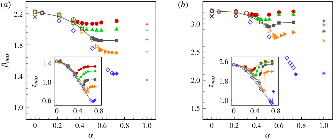
How the maximal spreading changes with
 $\unicode[STIX]{x1D6FC}$
relies heavily on the specific flow regime. However, it is difficult to quantitatively define the boundary between the flow regimes,
 $\unicode[STIX]{x1D6FC}_{c}$
, simply based on the morphology of the impacting compound drop; see, for example, the onset of the regime transition in figures 2(c) and 3(b). Therefore, we use
 $t_{max}$
to distinguish the two regimes. Figure 5 shows
 $\unicode[STIX]{x1D6FD}_{max}$
(and
 $t_{max}$
in the inset) as a function of
 $\unicode[STIX]{x1D6FC}$
at
 $We=50$
and 500, respectively. We can see that with the increase of
 $\unicode[STIX]{x1D6FC}$
,
 $t_{max}$
first descends, and turns to ascend. The outward motion of the drop is primarily hindered by the capillary pressure at the front of spreading (figure 3), of which the magnitude is determined by the surface tension coefficients and the local curvature (characterized by the height of the rim or the liquid film). At the onset of regime transition, there is hardly any rim formation, and thus the compound drop maintains a relatively high local curvature at its front during the spreading, compared to those away from the regime boundary (figure 2). Consequently, it leads to the relatively low
 $t_{max}$
at the onset of regime transition. We tentatively expect that the regime transition occurs when
 $t_{max}$
reaches its lowest value. Furthermore, the turning point of
 $t_{max}$
also indicates a change in the manner how
 $\unicode[STIX]{x1D6FD}_{max}$
varies with
 $\unicode[STIX]{x1D6FC}$
. As shown in figure 5,
 $\unicode[STIX]{x1D6FD}_{max}$
decreases with increasing
 $\unicode[STIX]{x1D6FC}$
in the regime of jammed spreading, while it shows insignificant changes with
 $\unicode[STIX]{x1D6FC}$
in the regime of joint rim formation. All these justify the definition of
 $\unicode[STIX]{x1D6FC}_{c}$
by
 $\unicode[STIX]{x1D6FC}$
at the turning point of
 $t_{max}$
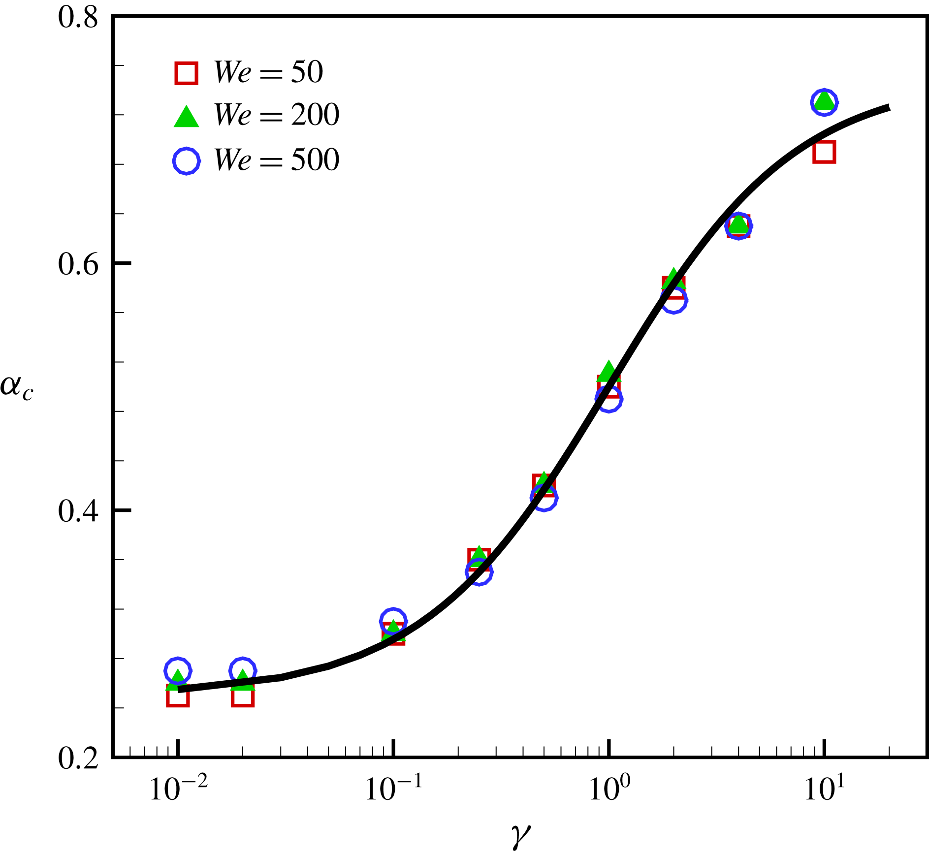
. It can be seen in figure 6 that
 $\unicode[STIX]{x1D6FC}_{c}$
generally increases with
 $\unicode[STIX]{x1D6FE}$
, and is not sensitive to the Weber number. Moreover, data fitting indicates that
 $\unicode[STIX]{x1D6FC}_{c}$
and
 $\unicode[STIX]{x1D6FE}$
can be well correlated by
 $$\begin{eqnarray}\unicode[STIX]{x1D6FC}_{c}\approx \frac{3}{4}-\frac{1}{2(1+\unicode[STIX]{x1D6FE})}.\end{eqnarray}$$
In the case of
 $\unicode[STIX]{x1D6FC}\rightarrow 0$
and
 $\unicode[STIX]{x1D6FC}\rightarrow 1$
(with no contact between the inner and outer interfaces), the compound drop can be simply modelled by a pure drop with a corrected surface tension coefficient – specifically
 $\unicode[STIX]{x1D70E}_{13}$
in the former and
 $(1+\unicode[STIX]{x1D6FE})\unicode[STIX]{x1D70E}_{13}$
in the latter. Therefore,
 $\unicode[STIX]{x1D6FD}_{max}$
in both cases in principle can be predicted by (1.1). The predicted values (
 $\unicode[STIX]{x1D6FD}_{\unicode[STIX]{x1D6FC}\rightarrow 0}$
and
 $\unicode[STIX]{x1D6FD}_{\unicode[STIX]{x1D6FC}\rightarrow 1}$
) are in agreement with the numerical results (figure 5), approximately with a maximum difference of 6 %.
Numerical results of maximal spreading for impacting compound drops at
 $We=50$
(a) and
 $We=500$
(b), for various
 $\unicode[STIX]{x1D6FE}$
: 0.25 (○), 0.5 (▵), 1 (▫), 2 (▹) and 10 (♢). The variation of
 $t_{max}$
with
 $\unicode[STIX]{x1D6FC}$
is shown in the corresponding inset. The filled symbols denote the regime of joint rim formation, and the open symbols denote the regime of jammed spreading. The theoretical predictions of
 $\unicode[STIX]{x1D6FD}_{\unicode[STIX]{x1D6FC}\rightarrow 0}$
and
 $\unicode[STIX]{x1D6FD}_{\unicode[STIX]{x1D6FC}\rightarrow 1}$
are represented by the symbols
 $\times$
and *, respectively. The lines serve as a guide to the eyes.

3.3 Universal rescaling
Numerical results of
 $\unicode[STIX]{x1D6FC}_{c}$
for different
 $\unicode[STIX]{x1D6FE}$
and
 $We$
. The curve represents the data fitting by (3.1).

From the analysis above, we can see that the maximal spreading ratio of impacting compound drops depends on
 $We$
,
 $\unicode[STIX]{x1D6FC}$
,
 $\unicode[STIX]{x1D6FE}$
and the specific flow regime. Similarly to pure drops, it is desirable for the compound drops to have a universal rescaling of
 $\unicode[STIX]{x1D6FD}_{max}$
that takes all these factors into account. Interestingly, we discover that this can be done by integrating a corrected Weber number
 $We^{\ast }$
into (1.1).
We notice that in the regime of joint rim formation, the inner interface evolves with the outer one in a synchronized manner (figures 2
d and 3
c). Moreover,
 $\unicode[STIX]{x1D6FD}_{max}$
is not very sensitive to
 $\unicode[STIX]{x1D6FC}$
but is to
 $\unicode[STIX]{x1D6FE}$
, and characterized by
 $\unicode[STIX]{x1D6FD}_{\unicode[STIX]{x1D6FC}\rightarrow 1}$
(figure 5). This implies that we can define
 $$\begin{eqnarray}We^{\ast }=\frac{We}{1+\unicode[STIX]{x1D6FE}},\quad \text{for }\unicode[STIX]{x1D6FC}\geqslant \unicode[STIX]{x1D6FC}_{c}.\end{eqnarray}$$
For the regime of jammed spreading, the interaction between the inner and outer interfaces is more complicated. An important question in defining
 $We^{\ast }$
is how much of the kinetic energy of the inner droplet contributes to the spreading of the compound drop. Obviously, the answer is 100 % when
 $\unicode[STIX]{x1D6FE}\rightarrow 0$
. Similarly, we can have
 $We^{\ast }\rightarrow We$
when
 $\unicode[STIX]{x1D6FC}\rightarrow 0$
. Also, we note that
 $\unicode[STIX]{x1D6FD}_{max}$
varies smoothly with
 $\unicode[STIX]{x1D6FC}$
(figure 5), even in the vicinity of the cross-over between the regimes, i.e.
 $\unicode[STIX]{x1D6FC}=\unicode[STIX]{x1D6FC}_{c}$
. Therefore, it is reasonable to expect that
 $We^{\ast }$
in the regime of jammed spreading should approach
 $We/(1+\unicode[STIX]{x1D6FE})$
when
 $\unicode[STIX]{x1D6FC}\rightarrow \unicode[STIX]{x1D6FC}_{c}$
. Taking these into account and assuming that the contribution of kinetic energy of the inner droplet decreases linearly with increasing
 $\unicode[STIX]{x1D6FC}$
, we can obtain
 $$\begin{eqnarray}We^{\ast }=\left(1-\frac{\unicode[STIX]{x1D6FC}}{\unicode[STIX]{x1D6FC}_{c}}\frac{\unicode[STIX]{x1D6FE}}{1+\unicode[STIX]{x1D6FE}}\right)We,\quad \text{for }\unicode[STIX]{x1D6FC}<\unicode[STIX]{x1D6FC}_{c}.\end{eqnarray}$$
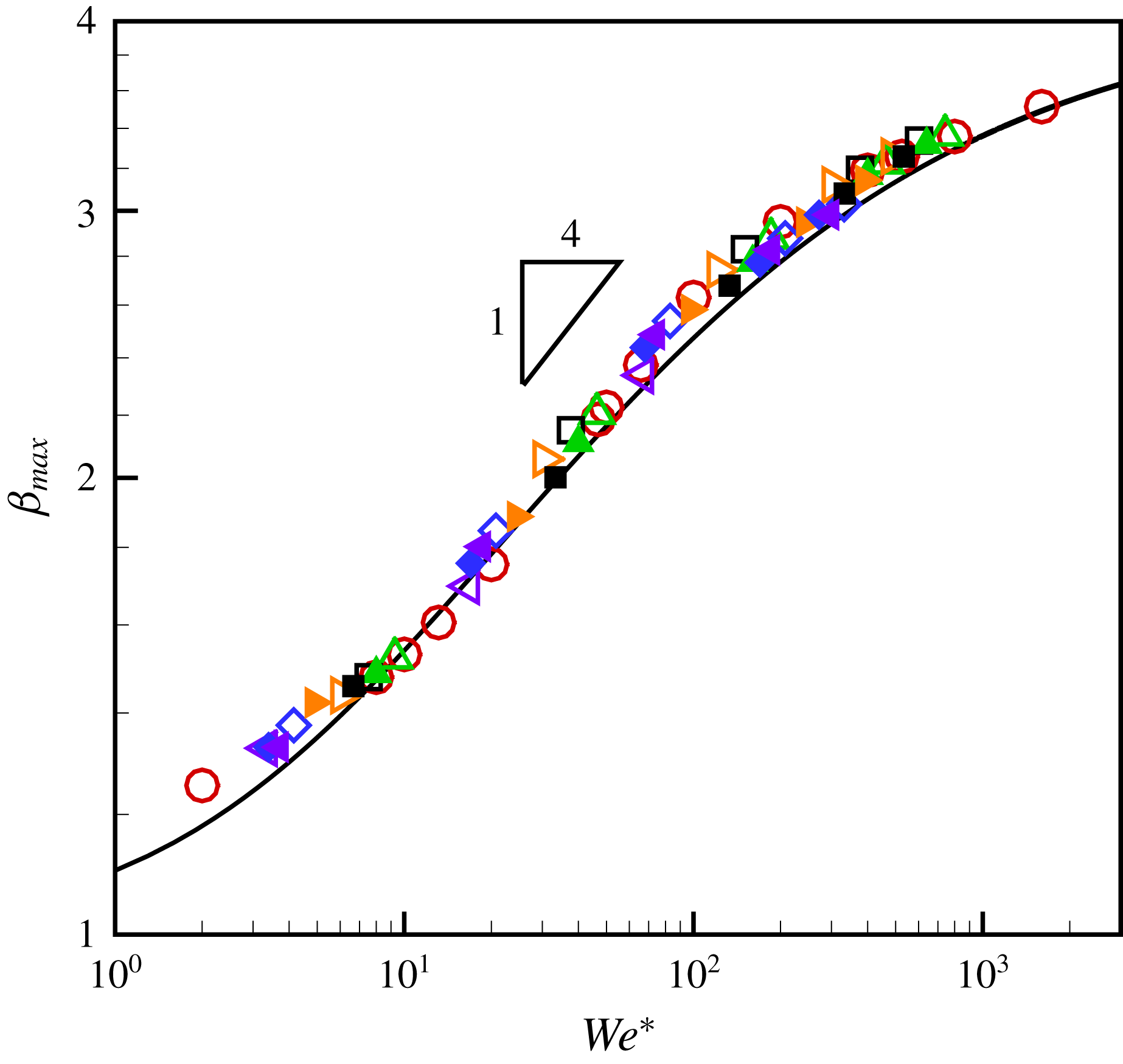
We correct the Weber number in figure 4 using (3.2) and (3.3), and present the numerical results in figure 7 with respect to
 $\unicode[STIX]{x1D6FD}_{max}$
versus
 $We^{\ast }$
. All the results collapse onto a single curve, which can be well represented by (1.1). This indicates that a universal rescaling can also be achieved for impacting compound drops by integrating
 $We^{\ast }$
into (1.1). Interestingly, we observe that the results for
 $20\leqslant We^{\ast }\leqslant 200$
can be represented well by
 $\unicode[STIX]{x1D6FD}_{max}\sim (We^{\ast })^{1/4}$
, i.e. the capillary regime in Clanet et al. (Reference Clanet, Béguin, Richard and Quéué2004). The flow is expected to enter the viscous regime when
 $WeRe^{-2/5}>4$
(Eggers et al.
Reference Eggers, Fontelos, Josserand and Zaleski2010), i.e.
 $We>120$
here, which is also consistent with our numerical results with respect to
 $We^{\ast }$
. These indicate the compatibility between the universal rescaling, which originates from energy conservation, and the scaling law of
 $We^{1/4}$
, which arises from momentum conservation.
Universal rescaling of maximal spreading ratio of an impacting compound drop as a function of
 $We^{\ast }$
. These cases are the same as in figure 4, including pure drops (○), those with fixed
 $\unicode[STIX]{x1D6FE}=2$
and various
 $\unicode[STIX]{x1D6FC}$
(
 $=0.064$
(▵), 0.216 (▫), 0.343 (▹), 0.512 (♢) and 0.729 (◃)), and those with fixed
 $\unicode[STIX]{x1D6FC}$
(
 $=0.512$
) and various
 $\unicode[STIX]{x1D6FE}$
(
 $=0.25$
(▴), 0.5 (▪), 1 (▸), 4 (♦) and 10 (◂)). The solid curve represents the relation (1.1) with
 $We^{\ast }$
as the variable.

4 Conclusion
We have simulated the impact dynamics of a compound drop on a wall using a ternary-fluid diffuse-interface method, and quantitatively investigated the effects of
 $\unicode[STIX]{x1D6FC}$
and
 $\unicode[STIX]{x1D6FE}$
on
 $\unicode[STIX]{x1D6FD}_{max}$
at moderate Weber and Reynolds numbers. Based on the spreading morphology of the compound drop, two flow regimes have been identified – i.e. jammed spreading and joint rim formation; they were found to have effects on
 $\unicode[STIX]{x1D6FD}_{max}$
. The regime transition occurs at a critical value of
 $\unicode[STIX]{x1D6FC}$
, i.e.
 $\unicode[STIX]{x1D6FC}_{c}$
, which appears to be insensitive to
 $We$
but sensitive to
 $\unicode[STIX]{x1D6FE}$
. Interestingly, we found that the universal rescaling for the pure drops proposed by Lee et al. (Reference Lee, Laan, De Bruin, Skantzaris, Shahidzadeh, Derome, Carmeliet and Bonn2016) can be extended to prediction of the maximal spreading ratio for compound drops, if a corrected Weber number
 $We^{\ast }$
is used. The correction of the Weber number takes
 $\unicode[STIX]{x1D6FC}$
,
 $\unicode[STIX]{x1D6FE}$
,
 $\unicode[STIX]{x1D6FC}_{c}$
and
 $We$
into account. As a result, good agreement has been achieved between the prediction and numerical results for a wide range of
 $We^{\ast }$
(
 ${\sim}10{-}1000$
).
In the present study, we only consider compound drops with two liquids of equal density and viscosity. Differences in density and/or viscosity may also play a role in the maximal spreading of the compound drop. This is beyond the scope of the present study, and will be the focus of our future research.
Acknowledgements
We are grateful for the support of the National Nature Science Foundation of China (grant nos 11425210, 11621202, 11672288, 11702288), the Strategic Priority Research Program of the Chinese Academy of Sciences (grant no. XDB22040103) and the Fundamental Research Funds for the Central Universities.