


INTRODUCTION
Significant progress had been achieved in pursuing high power, high efficiency, high-power microwave (HPM) devices (Chen et al., Reference Chen, Liu, Huang, Song, Fan and Wang2002; Eltchaninov et al., Reference Eltchaninov, Korovin, Rostov, Pegel, Mesyats, Rukin, Shpak, Yalandin and Ginzburg2003; Li et al., Reference Li, Shu, Yuan, Zhu, Liu, Wang and Zhang2010; Xiao et al., Reference Xiao, Zhang, Zhang, Li, Zhang, Song, Hu, Sun, Huo, Chen, Zhang and Liu2010; Zhang et al., Reference Zhang, Yuan and Liu2010), and the study of HPM relativistic Cherenkov oscillators with the capability of generating dual and multiple microwave frequencies simultaneously in one beam shot is becoming a novel and attractive topic recently (Chen et al., Reference Chen, Wang, Meng and Fan2009; Ginzburg et al., Reference Ginzburg, Rozental and Sergeev2003a; Reference Ginzburg, Rozental and Sergeev2003b; He et al., Reference He, Cao, Zhang, Wang and Ling2011; Ju et al., Reference Ju, Fan, Zhong and Shu2009; Ryskin et al., Reference Ryskin and Titov2001; Tang et al., Reference Tang, Meng, Li, Zheng, Yin and Wang2012; Wang et al., Reference Wang, Zhang, Qian and Zhang2010; Reference Wang, Qian, Zhang, Zhang, Cao and Zhang2011; Yang et al., Reference Yang, Liang, Zhang, Li, Ma, Hu and Liu1999), for the radiation beating radio-frequency waves could be used for electronic warfare systems, and various communication and sounding systems. Chen et al. (Reference Chen, Wang, Meng and Fan2009) investigated the dual-frequency magnetically insulated transmission line oscillator (MILO) with azimuthal partition operating at L-band, the particle-in-cell (PIC) simulation results indicated that the power conversion efficiency was only about 8.1%. Yang et al. (Reference Yang, Liang, Zhang, Li, Ma, Hu and Liu1999) designed a T-type structured dual-band Cherenkov oscillator with a relativistic orotron and a relativistic backward-wave oscillator (RBWO), the radiation microwave signals traveled perpendicular to each other, operating at Ka-band and X-band, respectively. However, the necessity of synchronizing the two perpendicular electron beams makes it incompact and inapplicable for further practical use. He et al. (Reference He, Cao, Zhang, Wang and Ling2011) designed a dual-frequency high-power microwave generator based on transition radiation, but the large transverse dimension makes it incompact and unpractical. Ginzburg et al. (Reference Ginzburg, Rozental and Sergeev2003a; Reference Ginzburg, Rozental and Sergeev2003b) designed a dual-frequency RBWO with two-section SWSs. The modeling results using code KARAT showed that dual-frequency of 8.8 GHz and 10.3 GHz with radiation power of 1 MW and power efficiency of 10% were obtained. Wang et al. (Reference Wang, Zhang, Qian and Zhang2010; Reference Wang, Qian, Zhang, Zhang, Cao and Zhang2011) proposed a dual-band two-section RBWO with average microwave power of 380 MW and conversion efficiency of 11.7%, the dominant frequencies were 5.48 and 9.60 GHz. Furthermore, a dual-band dual-beam RBWO was also presented to improve the microwave power conversion efficiency. However, such multilayer oscillator is incompact and discommodious for practice use. In essence, such parallel structured dual-band HPM generator is consistent with the Cherenkov oscillators with single frequency.
Experimental and theoretical results have showed that coaxial RBWO (CRBWO) demonstrated obvious advantages in beam-wave interaction efficiency and microwave power handling capacity (Liu et al., Reference Liu, Xiao, Chen, Shao, Hu and Wang2008; Wen et al., Reference Wen, Li, Xie and Liu1999; Zheng et al., Reference Zheng, Minami, Amin and Watanable1995). And to increase the beating frequency of the radiation power of the dual-frequency oscillator, i.e., the frequency difference between the two frequencies, the Eigen modes of the two SWS sections should be far and clearly distinguished, which would lead to severe interactions between the beams bunches in the two sections and lower conversion efficiency, especially for dual-band oscillators.
So, in this paper, we presented a compact dual-band CRBWO with improved SWSs by introducing stepwise variation of coupling impedance and phase velocity and an asymmetric modulating resonant reflector, which would not only reflect the generating dual-band microwaves, but also preliminary modulate the relativistic electron beam (REB) to further enhance the beam-wave interaction efficiency. The design of variable coupling impedance is aimed to enhance the space harmonic and improve the synchronous beam-wave interaction efficiency in the second SWS section, which is beneficial for converting modulated electron beam power to microwave power and the handleability of the dual frequencies.
THEORY PRINCIPLES OF DUAL-BAND OPERATIONS IN SECTION SWS
In the two-section CRBWO with non-uniform SWSs, different operation regimes, i.e., single-frequency regime, periodic, and stochastic auto-modulation regimes, could be established in different sections by changing the interaction length of each section and the stepwise change of the mismatch between the space charge wave and synchronous eigenmode wave, i.e., the synchronous detuning (Ginzburg et al., Reference Ginzburg, Rozental and Sergeev2003a; Reference Ginzburg, Rozental and Sergeev2003b). The shift in synchronous detuning is provided by a stepwise variation of the corrugation period length of the SWS, i.e., the phase velocity of the Eigen mode wave. Furthermore, the SWS sections could oscillate approximately independently by optimizing the length of each section and the shift in synchronous detuning. For instance, the first SWS section oscillates in the single frequency regime with dominant frequency f 1 while the second section operates in the regime of auto-modulation with dominant frequency f 2, or, both oscillate in the single regime. Specially, the buildup of stochastic regime needs a 2 − 3 times system length of the single regime's (Kang et al., Reference Kang, Kim, Titov and Park2003), and longer guiding magnetic field length is needed. Therefore, the single frequency regime is selected as the operating regime of the two-section SWSs in this paper, and the PIC simulation model of our design is presented in Figure 1.
PIC simulation mode of the dual-band sectioned CRBWO. (a) annular cathode, (b) asymmetric resonant reflector, (c) SWS1, (d) tapered waveguide, (e) SWS2, (f) beam collector, (g) outlet.

One fact must be emphasized is that the oscillation independence of SWS sections is constrained in the operation regimes and oscillation frequencies. The generating microwave power of each section depends on the complicated boundary conditions of the whole two-section system, which shows interesting performance.
SYNCHRONOUS BEAM-WAVE INTERACTION ANALYSIS
Linear Wave Dispersion Relation
The high-frequency characteristics of the system, including the beam-wave interaction regions and operation mode of each SWS section, as well as the approximate values of the two dominant frequencies (Swegle et al., 1985; Zheng et al., Reference Zheng, Minami, Amin and Watanable1995), could be acquired by linear wave dispersion analysis of coaxial SWS.
The coaxial SWS system, as depicted in Figure 2, consists of a coaxial cylindrical waveguide with inner and outer wall radii R w1 and R w2 varying according to the relation:
 $$\left\{\matrix{R_{w1}=R_1 \cr R_{w2}=R_2+h\sin \lpar K_0 z\rpar} \right.\comma \;$$
where R 1 is the radius of the inner conductor and R 2 is the mean radius of outer conductor. K 0 = 2π/l 0 is the corrugation wave-number, l 0 is the length of corrugation period, h is the ripple amplitude.
The coaxial SWS mode.

The derivation of the dispersion relation for coaxial SWS with both inner and outer ripples has been given in a previous paper (Tang et al., Reference Tang, Meng, Li, Zheng, Yin and Wang2012). Taking the amplitude of the inner ripple to be zero, we can obtain the following dispersion equation:
 $$\det \lpar D\rpar =\det \left[\matrix{D^{\lpar 11\rpar } D^{\lpar 12\rpar } \cr D^{\lpar 21\rpar } D^{\lpar 22\rpar } } \right]=0\comma \;$$
where
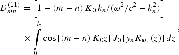 $$\eqalign{&D_{mn}^{\left({11} \right)}=\left[{1 - \left({m - n} \right)K_0\, k_n /\lpar {\rm \omega} ^2 /c^2 - k_n ^2 \rpar } \right]\cr &\matrix{ {} &{} &{} \cr } \times \int\limits_0^{l_0 } {\cos \left[{\left({m - n} \right)K_0 z} \right]J_0 \left[{y_n R_{w1} \lpar z\rpar } \right]dz} }\comma \;$$
 $$\eqalign{&D_{mn}^{\left({12} \right)}=\left[{1 - \left({m - n} \right)K_0\, k_n^{} /\lpar {\rm \omega} ^2 /c^2 - k_n ^2 \rpar } \right]\cr &\matrix{ {} &{} &{} \cr } \times \int\limits_0^{l_0 } {\cos \left[{\left({m - n} \right)K_0 z} \right]N_0 \left[{y_n R_{w1} \lpar z\rpar } \right]dz} }\comma \;$$
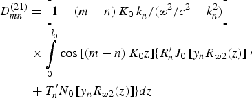 $$\eqalign{&D_{mn}^{\left({21} \right)}=\left[{1 - \left({m - n} \right)K_0\, k_n^{} /\lpar {\rm \omega} ^2 /c^2 - k_n ^2 \rpar } \right]\cr &\matrix{ {} &{} &{} \cr } \times \int\limits_0^{l_0 } {\cos \left[{\left({m - n} \right)K_0 z} \right]} \lcub R_n^{\prime} J_0 \left[{y_n R_{w2} \lpar z\rpar } \right]\cr &\matrix{ {} &{} &{} \cr }+T_n^{\prime} N_0 \left[{y_n R_{w2} \lpar z\rpar } \right]\rcub dz}\comma \;$$
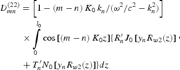 $$\eqalign{&D_{mn}^{\left({22} \right)}=\left[{1 - \left({m - n} \right)K_0\, k_n^{} /\lpar {\rm \omega} ^2 /c^2 - k_n ^2 \rpar } \right]\cr &\matrix{ {} &{} &{} \cr } \times \int\limits_0^{l_0 } {\cos \left[{\left({m - n} \right)K_0 z} \right]} \lcub R_n^{\prime} J_0 \left[{y_n R_{w2} \lpar z\rpar } \right]\cr &\matrix{ {} &{} &{} \cr }+T_n^{\prime} N_0 \left[{y_n R_{w2} \lpar z\rpar } \right]\rcub dz}\comma \;$$
and
 $$\eqalign{&R_n=G_n \left[{y_n J_0 \lpar x_n r_2 \rpar N_1 \lpar y_n r_2 \rpar - x_n J_1 \lpar x_n r_2 \rpar N_0 \lpar y_n r_2 \rpar } \right]\cr &\matrix{ {} &+\cr } L_n \left[{y_n N_0 \lpar x_n r_2 \rpar N_1 \lpar y_n r_2 \rpar - x_n N_1 \lpar x_n r_2 \rpar N_0 \lpar y_n r_2 \rpar } \right]}\comma \;$$
 $$\eqalign{&T_n=G_n \left[{x_n J_1 \lpar x_n r_2 \rpar J_0 \lpar y_n r_2 \rpar - y_n J_1 \lpar y_n r_2 \rpar J_0 \lpar x_n r_2 \rpar } \right]\cr &\matrix{ {} &+\cr } L_n \left[{x_n N_1 \lpar x_n r_2 \rpar J_0 \lpar y_n r_2 \rpar - y_n N_0 \lpar x_n r_2 \rpar J_1 \lpar y_n r_2 \rpar } \right]}\comma \;$$
 $$\eqalign{&R_n^{\prime}=G_n^{\prime} \left[{y_n J_0 \lpar x_n r_2 \rpar N_1 \lpar y_n r_2 \rpar - x_n J_1 \lpar x_n r_2 \rpar N_0 \lpar y_n r_2 \rpar } \right]\cr &\matrix{ {} &+\cr } L_n^{\prime} \left[{y_n N_0 \lpar x_n r_2 \rpar N_1 \lpar y_n r_2 \rpar - x_n N_1 \lpar x_n r_2 \rpar N_0 \lpar y_n r_2 \rpar } \right]}\comma \;$$
 $$\eqalign{&T_n^{\prime}=G_n^{\prime} \left[{x_n J_1 \lpar x_n r_2 \rpar J_0 \lpar y_n r_2 \rpar - y_n J_1 \lpar y_n r_2 \rpar J_0 \lpar x_n r_2 \rpar } \right]\cr &\matrix{ {} &+\cr } L_n^{\prime} \left[{x_n N_1 \lpar x_n r_2 \rpar J_0 \lpar y_n r_2 \rpar - y_n N_0 \lpar x_n r_2 \rpar J_1 \lpar y_n r_2 \rpar } \right]}\comma \;$$
where
 $$\left\{\matrix{G_n=x_n J_0 \lpar y_n r_1 \rpar N_1 \lpar x_n r_1 \rpar - y_n J_1 \lpar y_n r_1 \rpar N_0 \lpar x_n^{} r_1 \rpar \cr L_n=y_n J_1 \lpar y_n r_1 \rpar J_0 \lpar x_n r_1 \rpar - x_n J_0 \lpar y_n r_1 \rpar J_1 \lpar x_n^{} r_1 \rpar \cr G^{\prime} _n=x_n N_0 \lpar y_n r_{b1} \rpar N_1 \lpar x_n r_{b1} \rpar - y_n N_1 \lpar y_n r_{b1} \rpar N_0 \lpar x_n^{} r_{b1} \rpar \cr L^{\prime} _n=y_n N_1 \lpar Y_n r_{b1} \rpar J_0 \lpar X_n r_{b1} \rpar - x_n N_0 \lpar y_n r_{b1} \rpar J_1 \lpar x_n^{} r_{b1} \rpar } \right.\comma \;$$
where J 0, J 1, N 0, N 1 are the first and second kind Bessel functions of 0th and 1st order. k n = k 0 + nK 0, − K 0/2 ≤ k 0 < K 0/2, y n2 = ω2/c 2 − k n2,  $x_n^2=y_n^2 \left[{1 - {\rm \omega} _b^2 /\left({{\rm \omega} - k_n v_b } \right)^2 {\rm \gamma} _b ^3 } \right]$. γb is the relative factor and ωb = (I be/mɛ0S bv b)1/2 contains the influence of the beam space charge, where |I b | (I b < 0) is the injected beam current.
Eq. (2) is the dispersion relation involving the REB and coaxial SWS parameters. Although the equation involves an infinite matrix in principle, the matrix D is truncated to be an 18 × 18 matrix with −4 ≤ m, n ≤ 4 for a reasonable precision in this paper.
Solutions to the Dispersion Relation
The numerical results of Eq. (2) with SWS1 parameters and cathode voltage ψc of 510 kV, beam current | I b| of 9.03 kA are given in Figure 3. We can see that unstable beam-wave interaction occurs near the intersection of slow beam space-charge wave (SBSCW) and the quasi-TEM mode. Complex conjugate solutions of ω = ωr + iωi with 2.05 cm−1 ≤ k 0 ≤ 2.25 cm−1 are obtained where ωi is the time growth rate of the oscillation. The same interaction pattern repeated with the 1st space harmonic of the TM01 mode with 2.37 cm−1 ≤ k 0 ≤ 2.75 cm−1. The maximum value of ωi with TM01 mode is much larger than that of quasi-TEM mode, which reveals that the operation mode of SWS1 is TM01 mode (Swegle et al., Reference Swegle, Poukey and Leifeste1985). The dominant frequency of SWS1 where the maximum ωi occurs is 9.7 GHz.
Dispersion curves of SWS1 with | I b| = 9.03 kA, R 1 = 1.05 cm, R 2 = 2.9 cm, h = 0.2 cm, r 1 = 2.4 cm, r 2 = 2.6 cm, l 0 = 1.55 cm, and ψ c = 510 kV. FBSCW: fast beam space-charge wave, SBSCW: slow beam space-charge wave.

The numerical results of Eq. (2) with SWS2 parameters are depicted in Figure 4, and the similar approximation of the beam velocity at the entrance of SWS2 is made (Huang et al., Reference Huang, Wang, Xing and Deng2005; Tang et al., Reference Tang, Meng, Li, Zheng, Yin and Wang2012). Unstable beam-wave interaction occurs near the interaction of SBSCW and quasi-TEM mode with 0.91 cm−1 ≤ k 0 ≤ 2.78 cm−1, and further occurs near the interaction of SBSCW and the 1st space harmonic of the TM01 mode with 3.08 cm−1 ≤ k 0 ≤3.17 cm−1 and near the interaction of SBSCW and the 1st space harmonic of the TM02 mode with 3.74 cm−1 ≤ k 0 ≤ 3.97 cm−1. It's obvious that the maximum time growth rate ωi of quasi-TEM mode is much larger than that of TM01 mode and TM02 mode, which reveals that the operation mode of SWS2 is quasi-TEM mode, and the axial mode is nearly π mode. The dominant frequency of SWS2 where the maximum ωi occurs is 8.25 GHz. The calculated theoretical dominant frequencies of SWS1 and SWS2 approach the PIC simulation results which will be demonstrated below in this paper.
Dispersion curves of SWS2 with |I b| = 9.03 kA, R 1 = 1.05 cm, R 2 = 3.15 cm, h = 0.45 cm, r 1 = 2.4 cm, r 2 = 2.6 cm, l 0 = 1.20 cm, and γb = 1.74.

Coupling Impedance of Coaxial SWS
The coupling impedance of nth space harmonic of coaxial SWS is defined as (Yue et al., Reference Yue, Wang, Gong and Zhang2004):
 $$R_{cn}=\displaystyle{{E_{zn}^{} \left({\overline {r_b } } \right)E_{zn}^ {\ast} \left({\overline {r_b } } \right)} \over {2k_n^2 \displaystyle{1 \over {l_0 }}\sum\limits_{n=- \infty }^{+\infty } {\int\limits_0^{l_0 } {dz\int\limits_{R_{w1} }^{R_{w2} } {\displaystyle{1 \over 2}{\mathop{\rm Re}\nolimits} \left[{E_{rn} \left(r \right)\times H_{{\rm \varphi} n} \left(r \right)^ {\ast} } \right]\cdot 2{\rm \pi} rdr} } } }}\comma \;$$
where  $E_{zn}^{} \left({\overline {r_b } } \right)$ is the longitudinal electric field at the average beam radius
 $\overline {r_b }$,
 $E_{zn}^ {\ast} \left({\overline {r_b } } \right)$ is its conjugate, and
 $\overline {r_b }=\lpar r_1+r_2 \rpar /2$,
 $E_{rn} \left(r \right)$ and
 $H_{{\rm \varphi} n} \left(r \right)$ are radial electric field and poloidal magnetic field of the nth space harmonic, respectively. The plots of coupling impedance of SWS1 and SWS2 are presented in Figure 5. It can be seen that an obvious variable coupling impedance for quasi-TEM mode and TM01 mode of SWS1 and SWS2 is obtained in the higher frequency region: the coupling impedance for quasi-TEM mode increases, while for TM01 mode, it decreases, especially for the 1st space harmonic, which is beneficial for the beam-wave interaction in SWS2 and the handleability of the radiation dual frequencies.
Coupling impedance of (a) SWS1 for quasi-TEM mode, (b) SWS1 for TM01 mode, (c) SWS2 for quasi-TEM mode, (d) SWS2 for TM01 mode.

PIC SIMULATION RESULTS
The 2.5-D PIC simulation code CHIPIC (User's Manual of Code CHIPIC., 2004; Zhou et al., Reference Zhou, Liu, Liao and Li2009) is used to investigate the dual-band CRBWO with improved SWSs, and the PIC simulation configuration of the system is presented in Figure 1. The single annular electron beam is emitted from an annular cathode and travels through the asymmetric modulating resonant reflector (Teng et al., Reference Teng, Liu, Shao and Tang2009) and the sectioned coaxial SWSs, where the beam-wave interactions take place and the microwave power is generated. The reflector reflects the generating dual frequencies to the collecting end of the system. In this paper, the asymmetric modulating resonant reflector is first introduced to the design of dual-band Cerenkov oscillator and the width of the upper cavity of the reflector l 1 is set to be 0.9 cm, the width of the lower cavity l 2 is set to be 1.2 cm. A segment of tapered wave-guide between the two SWSs with a length of l d is used to realize optimal conditions for the interaction between the beam space charge wave with the backward −1st harmonic and the forward harmonic (Kitsanov et al., Reference Kitsanov, Klimov, Korovin, Kurkan, Pegel and Polevin2003).
Figure 6 shows the phase-space plot of the electron beam in the two-section CRBWO, which shows that the electron bunches are formed in both SWS1 and SWS2. The pre-modulation of the REB (region from −3.8 cm to 0.0 cm s) is attributed to the asymmetric reflector. Due to the improvement in the SWSs with variable coupling impedance, the electron bunches in SWS2 are still formed with a better quality than that in the usual two-section SWSs (Tang et al., Reference Tang, Meng, Li, Zheng, Yin and Wang2012). Figure 7 gives the axial electric field distribution of the two-section CRBWO. It can be seen that a peak of the axial electric field appears within the region of the reflector, and what's more, the axial electric field does not decrease in SWS2, and the peaks of the axial electric field in SWS2 can be even larger than that in SWS1. Therefore, as the electron beam travels toward the beam collector, the well-modulated electron bunches will interact with an enhanced axial electric field and lose energy continuously at SWS2.
Phase-space plot of the dual-band CRBWO with variable coupling impedance.

Axial electric field distribution.

When the diode voltage is 510 kV, the beam current is 9.03 kA, and the guiding magnetic field is 0.73 T, a dual-band microwave radiation spectrum with a high purity is acquired, as illustrated in Figure 8, which demonstrates that the dual frequencies obtained are 8.1 GHz and 9.9 GHz, corresponding to C-band and X-band, respectively, and the frequency difference is 1.8 GHz. Little spurious frequency component is observed, which is the operation characteristic of stationary single regime (Carmel et al., Reference Carmel, Lou, Rodgers, Guo, Destler, Granatstein, Levush, Antonsen and Bromborsky1992; Ginzburg et al., Reference Ginzburg, Zaitsev, Ilyakov, Kulagin, Novozhilova, Rozenthal and Sergeev2002; Ryskin et al., 2001; Swegle et al., Reference Swegle, Poukey and Leifeste1985). That is to say, stationary single-frequency regimes operating at 8.1 and 9.9 GHz are successfully established in the dual-band CRBWO. Figure 8b presents the time-frequency plots of the dual-band frequencies. We can see that the C-band frequency component begins to oscillate at 3 ns and the X-band component oscillation begins at 11 ns. The oscillation of C-band component sets up earlier than that of the X-band component, and the dual-band signals oscillate with approximately equal strength.
Generating dual-frequency (a) electric field spectrum, and (b) its time-frequency analysis. l d = 18 mm.

The instantaneous radiation power of the dual-band CRBWO is illustrated in Figure 9a, and Figure 9b presents the magnification of the instantaneous beating microwave power from 20 ns to 35 ns. It is obvious that the beating frequency of the radiation power is 1.9 GHz, falling in L-band. The peak value of the radiation microwave power is 2.5 GW, and the beating of the synthetic radiation power of our design in this paper is more clear and stable.
Time development of the PIC simulation results of the dual-band CRBWO: (a) instantaneous microwave power, (b) magnification of the instantaneous power.

The average power of the dual-band oscillator is about 1.0 GW, as given in Figure 10. Taking that the diode voltage is 510 kV and the beam current is 9.03 kA, the power conversion efficiency of our designed dual-band CRBWO is 21.7%, which is greater than that obtained by dual-band non-coaxial RBWOs, dual-frequency MILOs and other dual-frequency HPM sources.
Average power at the outlet.

In the design of the dual-band CRBWO with SWSs improvement, it is found that variations in the length of the tapered waveguide between SWS1 and SWS2 are found to significantly affect the dual frequencies and the radiation power of each section. Unlike the results in a previous paper analyzing X-band dual frequencies (Tang et al., Reference Tang, Meng, Li, Zheng, Yin and Wang2012), in this paper, perhaps because of the enhanced space harmonic and the reduction of the beam energy scatter in SWS2, both the dual frequencies demonstrate periodic-like dependence on l d, as presented in Figure 11, and this is the first time that observe dual-frequency agility in dual-band oscillator. And it is interesting to find that when the C-band signal locates near the crest, the X-band component falls into its valley, and vice versa.
Dual-frequency agility: (a) X-band microwave, (b) C-band microwave.

Figure 12 illustrates the time-frequency analysis of the dual-band radiation with different l d values. When l d is taken to be 1 mm, the X-band signal oscillates with relative higher strength than the C-band component. When l d is taken to be 44 mm, the C-band signal oscillates with relative higher strength than the X-band component. And, no matter which component oscillates with higher strength, the C-band oscillation always set-up earlier than the X-band oscillation.
Time-frequency analysis of the radiation with l d to be (a) 1 mm and (b) 48 mm.

Taking that |A 1,2|2/4 is the relative energy yield from the electron beam in each section and (|A 1|2/|A 2|2) to be the energy ratio of SWS1 and SWS2 (Ginzburg et al., Reference Ginzburg, Rozental and Sergeev2003b), where A 1,2 are the amplitudes of the spectral components, we acquire the periodic-like dependence of P 2 on l d, as indicated in Figure 13, where P 2 is the energy yield from the electron beam in SWS2. One can find similar results on microwave power and frequency in single frequency HPM oscillators (Korovin et al., Reference Korovin, Kurkan, Loginov, Pegel, Polevin, Volkov and Zherlitsyn2003; Moreland et al., Reference Moreland, Schamiloglu and Lemke1995). However, the energy yield in SWS1 doesn't shows such variation, perhaps because the oscillation regime of the dual-band CRBWO is more complicated than that of regular single frequency RBWO.
Energy yield in SWS2 as a function of l d.

CONCLUSIONS
In conclusion, a high-efficiency dual-band CRBWO with improved sectioned coaxial SWS by introducing stepwise variation of coupling impedance and phase velocity is designed and presented in this paper. The energy scatter of the electron beam in SWS2 is decreased and the axial electric field in SWS2 can be even larger than that in SWS1, thus the well-modulated electron bunches will interact with an enhanced axial electric field and lose energy continuously. Investigated by using PIC code CHIPIC, the simulation results reveals that when the diode voltage is 510 kV and beam current is 9.03 kA, an average microwave power of 1.0 GW with power conversion efficiency of 21.7% is obtained. The power conversion efficiency of our designed dual-band CRBWO is greater than that obtained by dual-band non-coaxial RBWOs, dual-frequency MILOs and other dual-frequency HPM sources. Simultaneously radiating dual-band frequencies of 8.1 GHz and 9.9 GHz are obtained, corresponding to C-band and X-band, respectively.
A more clear and stable beating radiation microwave power with peak value of 2.5 GW is acquired, and the beating frequency of the radiation power is 1.9 GHz, falling in L-band.
By changing the length of the tapered waveguide between SWS1 and SWS2, both the dual –band frequencies demonstrate periodic-like dependence on l d, and this is the first time that observe dual-frequency agility in dual-band oscillator. The build-up of the dual-band frequencies are also analyzed, and it is interesting to observe that no matter which component of the dual-frequency oscillates with higher strength, the C-band oscillation always sets up earlier than the X-band oscillation. Furthermore, the microwave generated in SWS2 demonstrates periodic-like dependence on l d.
ACKNOWLEDGMENT
This work is supported by National Natural Science Foundation of China (Grant No. 60971034 and No.41104097) and by the Fundamental Research Funds for the Central Universities (No. ZYGX2011J045).



