I. INTRODUCTION
The concept of leaky wave antennas (LWAs) was initially introduced in the first half of the 20th century but it was not until the past decades when the development of planar LWAs drew interest on this kind of structures due to their multiple advantages like narrow and high directive beams, inherently simple feeding network, and reduced unit cell length. The low profile and easy manufacturing [Reference Jackson, Caloz and Itoh1] make them ideally suited for modern communication systems since they give high-quality performance at low cost [Reference Podilchak, Freundorfer and Antar2]. A new approach to design and manufacture LWAs based on metamaterials [Reference Liu, Caloz and Itoh3], in particular composite right/left-handed (CRLH) unit cells, has been utilized combining the above mentioned advantages of LWAs with those of CRLH structures such as continuous radiation from backfire to endfire, including broadside direction [Reference Caloz, Itoh and Rennings4–Reference Paulotto, Baccarelli, Frezza and Jackson7].
Beam steering of LWAs can be achieved by frequency tuning due to the dispersive characteristic of the phase constant β of the propagating wave. The radiation angle with respect to broadside of an LWA is determined by [Reference Johnson and Jasik8]
 $$\psi \lpar f\rpar = \sin ^{ - 1} \left[{\beta \lpar f\rpar /\beta _0 \lpar f\rpar } \right]\comma$$
where β 0 is the free-space phase constant. Most CRLH LWAs with different topologies, applications, and manufacture technologies use frequency tuning in order to achieve beam steering such as the prototype presented in [Reference Liu, Jackson and Long9] which is based on substrate integrated waveguide technology. In [Reference Hashemi and Itoh10], a CRLH LWA is used with the ability to steer the radiation beam from the backward to the forward quadrant by scanning the frequency from 3.4 to 4.3 GHz. Other authors have made use of the CRLH concept combining it with purpose-tailored materials such as ferrites [Reference Kodera and Caloz11]. However, for many applications beam steering is desirable at a fixed frequency. This can be done using tunable capacitors like semiconductor varactors [Reference Lim, Caloz and Itoh12, Reference Lim, Caloz and Itoh13] or p-i-n diodes [Reference Huang, Chiao and De Lisio14]. The poor performance of these semiconductor varactors at high frequencies has a big impact on the antenna efficiency and thus, limits the operation frequency to about 7 GHz. Another possibility for higher operation frequencies is the usage of liquid crystal (LC) at its nematic phase as a continuously tunable anisotropic dielectric [Reference Mueller, Goelden, Scheele, Wittek, Hock and Jakoby15]. By applying a static magnetic or electric field it is possible to orientate the LC molecules and hence vary its permittivity. The waveguide-based LWA prototype presented in [Reference Damm, Maasch, Gonzalo and Jakoby16] proves this concept at an operation frequency of 7.6 GHz using a magnetic biasing scheme. This type of biasing is also used in [Reference Roig, Maasch, Damm, Karabey and Jakoby17], where an LC-based tunable CRLH LWA shows a continuous beam steering of ±20° at 27 GHz. The bulkiness of the magnets used for a static magnetic biasing and the difficulty to manipulate them are the main drawbacks of this biasing technique. Hence, an electric biasing scheme that is easily integratable in planar tunable structures while offering the same performance as the magnetic one is desirable. In this work, both techniques are compared and evaluated. For this purpose, an LC-based tunable CRLH transmission line working at 27 GHz is designed and investigated.
II. UNIT CELL DESIGN
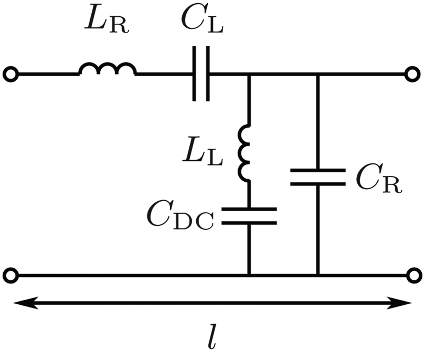
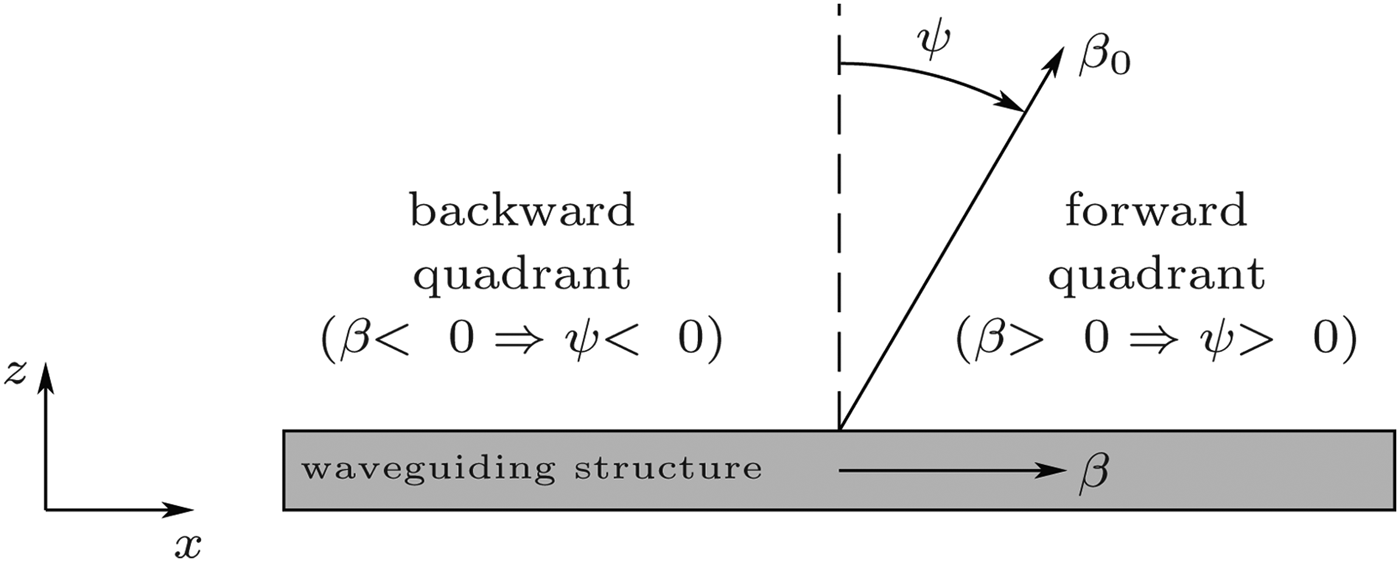
Figure 1 shows the equivalent circuit of the proposed extended CRLH unit cell. It is formed by series and shunt capacitances and inductances that create the left- and right-handed propagation bands. On one hand, the right-handed band (RHB), which is that of traditional transmission line models, is created by the series inductance L R and the shunt capacitance C R. In this band, the phase constant β and therefore the phase velocity v ph are both positive and the leaky wave is radiated into the forward quadrant. On the other hand, the series capacitance C L and shunt inductance L L are responsible for the left-handed band (LHB) where both, phase constant and phase velocity, are negative. In this case, the leaky wave is radiated into the backward quadrant [Reference Lim, Caloz and Itoh13]. This can be seen in Fig. 2, where the angle ψ is defined as in (1). For a seamless transition from the LHB to the RHB the unit cell has to be balanced [Reference Caloz and Itoh18], i.e. ω sh = ω se, where the shunt frequency is
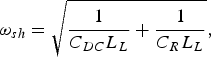 $$\omega _{sh} = \sqrt {\displaystyle{1 \over {C_{DC} L_L }} + \displaystyle{1 \over {C_R L_L }}}\comma$$
and the series frequency
 $$\omega _{se} = \displaystyle{1 \over {\sqrt {C_L L_R } }}.$$
Equivalent circuit of the modified CRLH unit cell.

Working principle of a leaky wave antenna.
A DC blocking capacitor C DC is added to the shunt branch of the CRLH unit cell for electric biasing purposes. In the present work, the CRLH unit cell is tuned both electrically and magnetically and its performance in both cases is compared. In order to study the influence of C DC on the final design, it is always incorporated to the unit cell independently of the tuning method applied. C DC creates an undesired stopband below
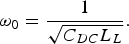 $$\omega _0 = \displaystyle{1 \over {\sqrt {C_{DC} L_L } }}.$$
Hence, C DC has to be as large as possible in order to shift its stopband out of the intended frequency range of operation and thereby make its effect negligible. If C DC is large enough, then the shunt frequency can be approximated by
 $$\omega _{sh} = \sqrt {\displaystyle{1 \over {C_{DC} L_L }} + \displaystyle{1 \over {C_R L_L }}} \approx \displaystyle{1 \over {\sqrt {C_R L_L } }}\comma$$
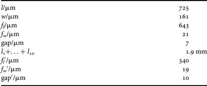
and the presented unit cell works as a conventional CRLH structure at the frequency range of operation. Fig. 3a depicts the layout of the designed unit cell in microstrip technology based on the proposed CRLH equivalent circuit. The corresponding element dimensions are listed in Table 1. The series branch corresponds to the main interdigital capacitor (IDC), composed of six fingers. The meander line represents the shunt inductance while the IDC at its end is the DC blocking capacitor C DC. The shunt capacitance is created between the complete unit cell and the ground plane below it. The microscope photo in Fig. 3b shows how the unit cell is periodically repeated to form the artificial transmission line. This scheme will be used for the magnetic biasing proof-of concept.
(a) Proposed unit cell layout. (b) Detailed photo of the manufactured metamaterial transmission line without the biasing lines.
Unit cell elements dimensions.
III. TECHNOLOGY AND MANUFACTURE
The fabricated metamaterial transmission line consists of 16 CRLH unit cells. A cross-sectional view of the completely mounted structure is depicted in Fig. 4a and explained in detail in this section. All unit cells are printed on a borofloat (BF33) glass substrate with ε r = 4.65 and tanδ = 0.008. This glass substrate is chosen not only because of its optimal behavior at microwave frequencies but also because its transparency enables easy alignment. The RF metalization is made of 2 µm thick gold on the bottom side of the glass substrate. A polyimide layer is spin coated with a height of 10 nm and subsequently mechanically rubbed with a velvet cloth. The aim of this is to anchor the LC molecules parallel to the polyimide grooves in the untuned state [Reference Goelden, Gaebler, Mueller, Lapanik, Haase and Jakoby19]. To provide mechanical stability to the complete structure, a brass block is used as a ground plane. A photo of the printed glass substrate and the metal block is shown in Fig. 4b. The complete transmission line with the tapers, all printed in the same glass substrate, has a length of 24.1 mm.
(a) Cross-sectional view of the proposed structure. (b) Glass substrate with printed CRLH transmission line and ground brass block.
The glass substrate with the RF structure on the bottom side is then fixed with conducting glue on top of the metal block forming a cavity with a height of 100 µm between both of them. This cavity is filled with LC TUD-649 with ε r⊥ = 2.43, ε r‖ = 3.22, tanδ ≤ 0.0066. ε r⊥ represents the permittivity for the orientation, where the LC molecules are oriented perpendicularly to the RF field, the unbiased state, whereas for ε r‖ the LC molecules are oriented parallel to the RF field, this is, the biased state. The orientation of the LC molecules and therefore its permittivity can be tuned either by applying a static magnetic or electric field.
For the magnetic biasing, a rare earth magnet with a field strength of 1T is used. For the electric biasing, highly resistive nickel chromium (NiCr) lines with a thickness of 20 nm and a width of 15 µm are implemented in the unit cell to distribute the tuning voltage along the structure. Figure 5 shows the modified unit cell including the NiCr biasing lines. The impact of these lines on the performance of the metamaterial transmission line is evaluated.
(a) Electric biasing scheme. (b) Periodically repeated CRLH with highly resistive NiCr lines for electric biasing.
IV. DISPERSION CHARACTERISTICS
Advanced design system (ADS) is used for the fullwave simulations of the CRLH transmission line, taking into account metallic and dielectric losses as well as radiation effects. For the magnetic biasing configuration, simulations are carried out on the unit cell scheme represented in Fig. 3b. For the case of electric tuning the highly resistive lines are also included in the simulations in the form as shown in Fig. 5. Both configurations are simulated and measured for both tuning states. To obtain the dispersion diagram, scattering parameter measurements of the transmission line consisting of 16 unit cells are carried out in an on-wafer measurement setup with GSG probes with 250 µm pitch. In this configuration, the transmission line is turned upside down and placed on a layer of absorber. For antenna purposes, contacting with K-connectors directly mounted on the glass is also possible. From the obtained S-parameters, the phase shift and its corresponding radiation angle are extracted and compared for both biasing configurations.
A) Magnetic biasing
For the magnetic biasing, the structure is positioned directly on top of the magnet. The simulated and measured unit cell phase shift is presented in Fig. 6a for the biased and unbiased states. Simulations show a stopband between 23.5 and 25 GHz for the biased state and 25.8 and 27.3 GHz for the unbiased state. As expected, due to a higher permittivity of the LC, the dispersion curve is shifted downwards in frequency for the biased state. In the measurement, the stopband disappears due to the anisotropy of the LC which cannot be taken into account in the simulations. This effect shifts the shunt and series frequencies in opposite directions and thus, cancels out the stopband. For the biased and unbiased states, the frequencies for the broadside radiation, i.e. where the radiation angle ψ = 0, are 28.15 GHz and 25.6 GHz, respectively. Since both measured dispersion curves are balanced, it is possible to vary the unit cell shift between βl = −0.04π and βl = 0.05π for a fixed frequency of 27 GHz. If the presented transmission line is used for LWA purposes, the radiation angle extracted from the measured phase shift according to equation (1) corresponds to a nearly symmetrical beam steering of ψ = −19.6° to ψ = 22.5° with respect to the broadside direction. This can be seen in Fig. 6b, where the extracted radiation angle along the frequency is represented.
(a) Measured and simulated unit cell phase shift with magnetic biasing. (b) Extracted radiation angle from the measured phase shift with magnetic biasing.
B) Electric biasing
For the electric biasing, DC voltages between 0 and 60 V are applied. In Fig. 7a, the simulated and measured dispersion diagrams are presented. Simulations show a stopband between 25.21 and 26.5 GHz for the biased state and from 26.8 to 28.23 GHz for the unbiased state. The stopband is shifted compared to the magnetically biased transmission line due to the highly resistive biasing lines. This effect is also present in the measured phase shift, where the stopband has almost disappeared. In the case of the measured phase shift at 60V the dispersion diagram shows a slight deviation compared to the simulated one. This is because an SOLT calibration is used during the measurements, so the effect of the taper between the designed transmission line and the probes is deembedded in a post-processing step using the simulated S-parameters of the taper. At 27 GHz, the measured phase shift per unit cell can be tuned between βl = −0.040π and βl = 0.049π.
(a) Measured and simulated unit cell phase shift with electric biasing. (b) Measured and simulated radiation angle with electric biasing.
For the case the presented transmission line is used for LWA purposes, the frequency dependent radiation angle obtained from the measured unit cell phase shift using equation (1) is presented in Fig. 7b. Here the effect of the deembedding is also visible. At 27 GHz, the measured angles for the electric biasing correspond to a nearly symmetrical beam steering range of ψ = −21.89° to ψ = 17.83° with respect to the broadside direction.
Figure 8 shows the simulated and measured S-parameters for the electric biasing for different tuning voltages. By varying the biasing voltage, the transmission bands can be shifted by 2 GHz. For the different tuning states |S 21| falls below −10 dB for frequencies corresponding to the stopband. This effect is also visible in |S 11|, since the structure is mismatched in the stopband and the input reflection increases up to −2.5 dB for 0V and −1.8 dB for 60V. The insertion loss is better than 0.9 dB per unit cell for the LHB and 0.37 dB per unit cell for the RHB, respectively.
Measured and simulated scattering parameters of the CRLH line consisting of 16 unit cells for different bias voltages.
The difference between the simulated and measured scattering parameters is caused by the effect of the deembedding of the taper after the SOLT calibration. However, the highly resistive biasing lines have minor impact on the phase shift of the unit cell.
V. CONCLUSION AND OUTLOOK
In this work, an LC-based tunable CRLH transmission line for future LWAs working at 27 GHz has been presented. The tuning of the LC is achieved by magnetic and electric biasing techniques specifically designed for planar structures. Different prototypes have been designed and manufactured for each biasing technique. For the electric biasing, highly resistive NiCr lines are integrated in the unit cell layout. The tuning of the LC and comparison of both prototypes has been done by simulation and measurements of the S-parameters and dispersion characteristics. From the obtained S-parameters, the corresponding radiation angles are extracted and a beam scanning range of ±20° at 27 GHz is achieved with both techniques. The electric biasing provides similar tuning behavior as the magnetic one with the advantage of being easily integratable in the unit cell layout. This electric biasing technique can be easily applied to different types of planar voltage tunable components such as LWAs with continuous beam scanning capability but also tunable phase shifters and filters.
ACKNOWLEDGEMENTS
The authors wish to acknowledge the financial support of the German Research Foundation within the research project DA1275/1 and Merck KGaA Darmstadt for providing liquid crystal material.
 María Roig received the degree in Electrical Engineering from the Technische Universität Darmstadt, Germany, in 2010. She is currently working toward the Dr.-Ing. degree at the Institute for Microwave Engineering and Photonics, Technische Universität Darmstadt. Her research interest focuses on the design and implementation of tunable antennas for microwave applications based on metamaterials and liquid crystals.
 Matthias Maasch received his Dipl. Ing. (FH) degree from the Hochschule Mannheim, Germany, in 2007. He is currently working toward the Dr.-Ing. degree at the Institute for Microwave Engineering and Photonics, Technische Universität Darmstadt. His current research activities focus on the design of tunable metamaterials for microwave applications based on liquid crystals.
Christian Damm received the Dr.-Ing. degree from Technische Universität Darmstadt, Germany, in 2010. He is currently a Post-Doc with the Institute for Microwave Engineering and Photonics at Technische Universität Darmstadt. His research interests include tunable microwave components, sensors and antennas based on metamaterials, and classic tunable media such as liquid crystals and ferroelectrics.
 Rolf Jakoby received the Dr.-Ing. degree from the University of Siegen, Germany, in 1990. In 1991, he joined the Research Center of Deutsche Telekom in Darmstadt, Germany. Since April 1997, he has had a Full Professorship in the Institute for Microwave Engineering and Photonics at Technische Universität Darmstadt, Germany. Prof. Jakoby is Editor-in-Chief of FREQUENZ, a member of the Society for Information Technology (ITG) of the VDE and a member of various societies of the IEEE. He is organizer of various workshops, member of various TPCs, and has been chairman of the European Microwave Conference 2007. In 1992, he received an award from the CCI Siegen and in 1997, the ITG-Prize for an excellent publication in the IEEE Transactions on Advanced Packaging.