1 Introduction
The actuator line model (ALM) represents lifting lines by means of a suitably coupled distribution of body forces in the momentum equation of the underlying flow solver. It is an efficient computational method to resolve atmospheric turbulence down to the blade chord scale. The ALM was originally developed by Sørensen & Shen (Reference Sørensen and Shen2002) to model wind turbine wakes in both uniform and turbulent inflow, with particular emphasis on wake interaction (see, for example, Ivanell, Sørensen & Henningson Reference Ivanell, Sørensen and Henningson2007; Troldborg, Sørensen & Mikkelsen Reference Troldborg, Sørensen and Mikkelsen2010; Troldborg et al. Reference Troldborg, Larsen, Madsen, Hansen, Sørensen and Mikkelsen2011a ; Troldborg, Sørensen & Mikkelsen Reference Troldborg, Sørensen and Mikkelsen2011b ). Ever since, the ALM has advanced the scientific knowledge of wind turbine wakes (see also Sørensen et al. Reference Sørensen, Mikkelsen, Henningson, Ivanell, Sarmast and Andersen2015; Breton et al. Reference Breton, Sørensen, Hansen, Sarmast and Ivanell2017).
In spite of recent enhancements to the ALM for improved predictions of blade tip loads (Shives & Crawford Reference Shives and Crawford2013), reduced grid effects (Jha et al. Reference Jha, Churchfield, Moriarty and Schmitz2014) and optimum smoothing length scales in the projection of body forces (Martinez-Tossas, Churchfield & Meneveau Reference Martinez-Tossas, Churchfield and Meneveau2017), the primary limitations of the ALM concept persist, specifically the overlap in momentum sources associated with spherical Gaussian body-force projection between adjacent actuator points and beyond the blade tips. This results in a given grid point being influenced by more than one actuator point, leading to a discretization error in the local trailing vorticity and, consequently, an incorrect downwash distribution along the lifting lines. Furthermore, the current ALM leads to force projection beyond the blade tip, which is both non-physical and dependent on the Gaussian projection width chosen on a given grid. Hence, it is inconsistent in its effect on computed blade tip loads.
The current limitations necessitate a more general body-force projection concept for lifting lines in computational fluid dynamics (CFD) solvers. At the same time, it is required that the new concept perform on the same computational grids and at the same expense as the standard ALM concept, thus not becoming a significantly more expensive actuator surface model (ASM) (see, e.g., Shen, Zhang & Sørensen Reference Shen, Zhang and Sørensen2009; Watters & Masson Reference Watters and Masson2010), with computational grid requirements of the same order as blade-resolved hybrid unsteady Reynolds-averaged Navier–Stokes (URANS) and large-eddy simulation (LES) analyses.
In this work, a brief description of the original ALM and recent improvements to it are presented first. Then, the actuator curve embedding (ACE) concept and implementation are introduced. Quantitative validation examples include an elliptic wing as well as parked and rotating wind turbine blades with various blade planform and tip shapes. Although the emphasis in this work is on wind turbines, the ACE concept can be universally applied to any fixed or rotary-wing system.
2 The ALM in OpenFOAM
This section briefly describes the underlying ALM methodology as implemented in an atmospheric boundary-layer (ABL) solver in OpenFOAM (Churchfield et al.
Reference Churchfield, Moriarty, Vijayakumar and Brasseur2010). The rotor blade or wing is discretized into a finite number (typically between 25 and 40) of actuator elements. Sectional lift and drag forces are computed at the centre of each of these actuator elements by interpolation of local flow-field data and using a table lookup for aerofoil properties. The computed blade forces at discrete actuator points are then projected onto the background Cartesian grid as spherical Gaussian body forces centred around each actuator element. The last term,
 $(F_{p})_{i}$
, in the following momentum equation corresponds to the body force:
 $$\begin{eqnarray}\frac{\unicode[STIX]{x2202}\overline{u}_{i}}{\unicode[STIX]{x2202}t}+\frac{\unicode[STIX]{x2202}(\overline{u}_{j}\overline{u}_{i})}{\unicode[STIX]{x2202}x_{j}}=-2\unicode[STIX]{x1D700}_{ijk}\unicode[STIX]{x1D6FA}_{j}\overline{u}_{k}-\frac{1}{\unicode[STIX]{x1D70C}_{0}}\frac{\unicode[STIX]{x2202}\tilde{p}}{\unicode[STIX]{x2202}x_{i}}-\frac{1}{\unicode[STIX]{x1D70C}_{0}}\frac{\unicode[STIX]{x2202}p}{\unicode[STIX]{x2202}x_{i}}-\frac{\unicode[STIX]{x2202}R_{ij}^{D}}{\unicode[STIX]{x2202}x_{j}}+\left(\frac{\unicode[STIX]{x1D70C}_{b}}{\unicode[STIX]{x1D70C}_{0}}-1\right)g_{i}+\frac{1}{\unicode[STIX]{x1D70C}_{0}}(F_{p})_{i}.\end{eqnarray}$$
In the present case, the momentum equation is for an ABL-LES, where
 $\unicode[STIX]{x2202}\overline{u}_{i}/\unicode[STIX]{x2202}t$
is the time rate of change of filtered velocity,
 $\unicode[STIX]{x2202}(\overline{u}_{j}\overline{u}_{i})/\unicode[STIX]{x2202}x_{j}$
is the convection term and
 $2\unicode[STIX]{x1D700}_{ijk}\unicode[STIX]{x1D6FA}_{j}\overline{u}_{k}$
is the Coriolis term due to planetary rotation. Furthermore,
 $\unicode[STIX]{x2202}\tilde{p}/\unicode[STIX]{x2202}x_{i}$
is the gradient of the modified pressure variable
 $\tilde{p}$
, which is the deviation in resolved-scale static pressure from its time-averaged value and lumped with one-third of the trace of the stress tensor
 $\unicode[STIX]{x1D70F}_{kk}/3$
. The driving pressure gradient is
 $\unicode[STIX]{x2202}p/\unicode[STIX]{x2202}x_{i}$
, while
 $\unicode[STIX]{x2202}R_{ij}^{D}/\unicode[STIX]{x2202}x_{j}$
is the divergence of the deviatoric part of the fluid stress tensor. The term
 $(\unicode[STIX]{x1D70C}_{b}/\unicode[STIX]{x1D70C}_{0}-1)g_{i}$
models buoyancy effects using the Boussinesq approximation, where
 $g_{i}$
represents gravity and
 $\unicode[STIX]{x1D70C}_{0}$
is the reference fluid density. OpenFOAM uses finite-volume discretization, with second-order-accurate spatial central differencing and a second-order-accurate Crank–Nicolson method for time integration. A pressure-implicit splitting operation (PISO) algorithm is used for the pressure, while the Smagorinsky model accounts for subgrid-scale effects.
The transformation of an elemental blade load
 $\boldsymbol{f}_{N,m}$
into a volumetric body force
 $\boldsymbol{F}_{p}$
is typically achieved by a Gaussian projection function, shown in vector form as
 $$\begin{eqnarray}\boldsymbol{F}_{p}(x_{P},y_{P},z_{P})=-\mathop{\sum }_{N}\mathop{\sum }_{m}\boldsymbol{f}_{N,m}(x_{N,m},y_{N,m},z_{N,m})\unicode[STIX]{x1D702}_{N,m},\end{eqnarray}$$
where the projection function is
 $$\begin{eqnarray}\unicode[STIX]{x1D702}_{N,m}=\frac{1}{\unicode[STIX]{x1D716}^{3}\unicode[STIX]{x03C0}^{3/2}}\exp [-(|\boldsymbol{r}|/\unicode[STIX]{x1D716})^{2}].\end{eqnarray}$$
Here,
 $N$
is the blade index,
 $m$
is the actuator point index,
 $|\boldsymbol{r}|=|\boldsymbol{r}_{p}-\boldsymbol{r}_{N,m}|$
is the distance from grid cell
 $\boldsymbol{r}_{p}=(x_{P},y_{P},z_{P})^{\text{T}}$
to the actuator point
 $\boldsymbol{r}_{N,m}=(x_{N,m},y_{N,m},z_{N,m})^{\text{T}}$
and
 $\unicode[STIX]{x1D716}$
is a Gaussian projection radius. The elemental blade load is a function of the sectional lift and drag forces according to
 $$\begin{eqnarray}\boldsymbol{f}_{N,m}(x_{N,m},y_{N,m},z_{N,m})={\textstyle \frac{1}{2}}\unicode[STIX]{x1D70C}_{0}V_{rel}^{2}c~(c_{l}~\boldsymbol{e}_{l}+c_{d}\boldsymbol{e}_{d})\unicode[STIX]{x1D6E5}_{b},\end{eqnarray}$$
where
 $c$
is the local chord length,
 $c_{l}$
and
 $c_{d}$
are sectional aerofoil lift and drag coefficients,
 $\boldsymbol{e}_{l}$
and
 $\boldsymbol{e}_{d}$
are unit vectors perpendicular and parallel to the sectional relative velocity vector
 $\boldsymbol{V}_{rel}$
and
 $\unicode[STIX]{x1D6E5}_{b}$
is the width of the sectional actuator element. It should be noted that
 $c_{l}$
and
 $c_{d}$
are determined from table lookup using the local angle of attack
 $\unicode[STIX]{x1D6FC}$
, which is the difference between the directions of
 $\boldsymbol{V}_{rel}$
and the sectional chord line (Sørensen & Shen Reference Sørensen and Shen2002; Calaf, Meneveau & Meyers Reference Calaf, Meneveau and Meyers2010; Lu & Porté-Agel Reference Lu and Porté-Agel2011; Meyers & Meneveau Reference Meyers and Meneveau2012; Chatelain et al.
Reference Chatelain, Backaert, Winckelmans and Kern2013). It is recommended that the Gaussian projection radius
 $\unicode[STIX]{x1D716}$
be based on the grid spacing
 $\unicode[STIX]{x1D6E5}_{grid}$
(Troldborg et al.
Reference Troldborg, Sørensen and Mikkelsen2010) as
 $$\begin{eqnarray}\text{ALM:}\quad \unicode[STIX]{x1D716}/\unicode[STIX]{x1D6E5}_{grid}=2.\end{eqnarray}$$
Blade tip loads are typically overpredicted, if no appropriate tip-loss correction (Shen et al.
Reference Shen, Mikkelsen, Sørensen and Bak2005) is used; see § 4. Recent work by the authors was driven by the hypothesis that the Gaussian projection radius
 $\unicode[STIX]{x1D716}$
is related to the primary mode of the blade loading within an ALM concept. These modifications to the ALM, in the following referred to as ALM*, led to improved prediction of integrated power and sectional blade loads (Jha et al.
Reference Jha, Churchfield, Moriarty and Schmitz2014) and also captured smaller-scale turbulence-induced unsteadiness of sectional blade loads (Jha & Schmitz Reference Jha and Schmitz2016). This was accomplished using a variable Gaussian radius
 $\unicode[STIX]{x1D716}(r)$
, which was determined using an equivalent elliptic planform
 $c^{\ast }(r)$
of the same aspect ratio,
 $AR$
, as the actual blade as
 $$\begin{eqnarray}\text{ALM*:}\quad \unicode[STIX]{x1D716}/c^{\ast }=C_{1}(\unicode[STIX]{x03C0}AR)=\unicode[STIX]{x1D716}_{0}/c_{0},\end{eqnarray}$$
where
 $C_{1}=0.25(n_{max}\unicode[STIX]{x1D6E5}_{grid}/R)$
. Furthermore,
 $\unicode[STIX]{x1D716}_{0}$
and
 $c_{0}$
are respective values at the midspan of the blade or wing, with
 $\unicode[STIX]{x1D716}_{0}=n_{max}\unicode[STIX]{x1D6E5}_{grid}$
and
 $n_{max}$
being determined for a given
 $\unicode[STIX]{x1D6E5}_{grid}$
through
 $C_{1}\in [0.025,0.030]$
. While this was a step towards more accurate modelling of rotor blades keeping
 $\unicode[STIX]{x1D6E5}_{b}/\unicode[STIX]{x1D6E5}_{grid}\geqslant 1.5$
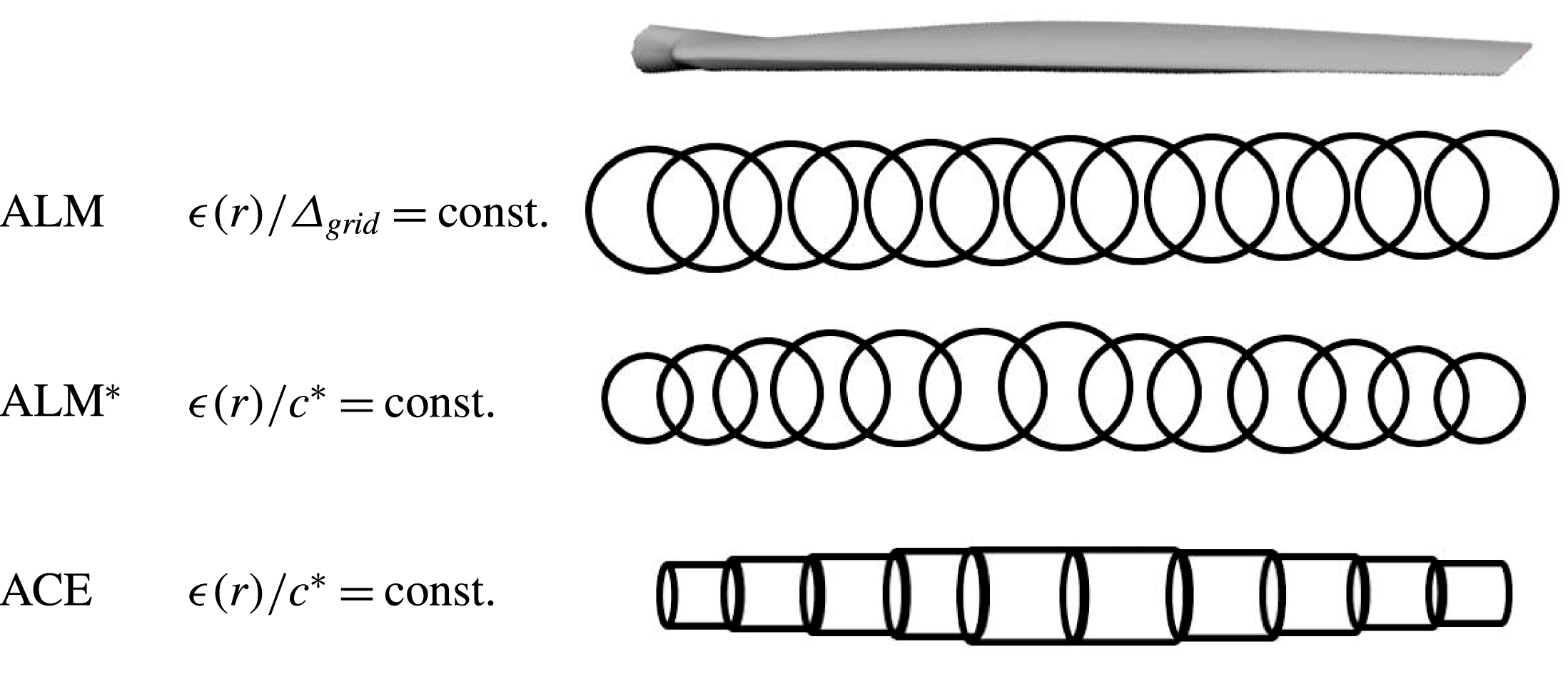
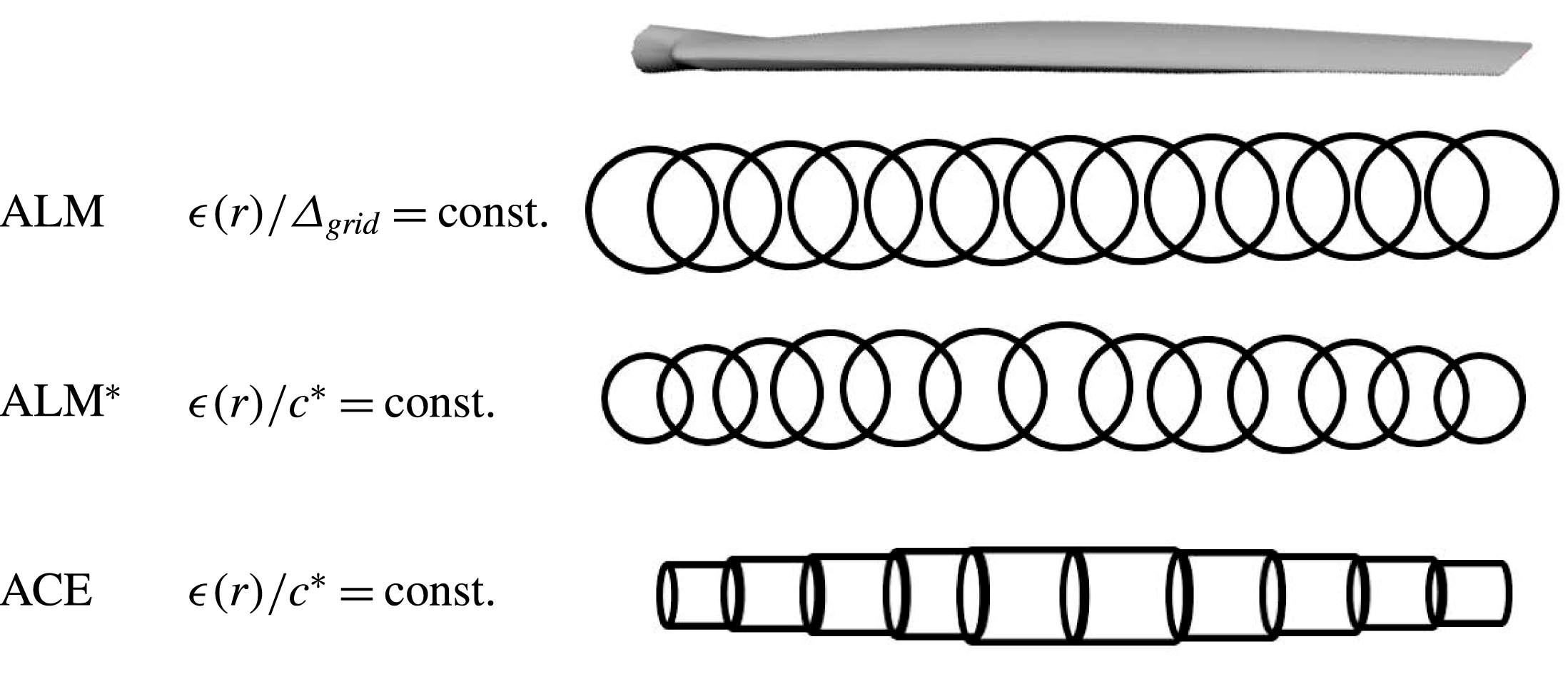
, the projection function (equation (2.3)) remained a spherical Gaussian that overlapped with adjacent body-force projections; see figure 1. While the elliptic
 $\unicode[STIX]{x1D716}$
-based ALM* is more accurate compared with the standard ALM and is consistent with grid refinements, the overlap is not fully eradicated. A different approach was recently taken by Churchfield et al. (Reference Churchfield, Schreck, Martinez-Tossas, Meneveau and Spalart2017) and Martinez-Tossas et al. (Reference Martinez-Tossas, Churchfield and Meneveau2017), where an optimized Gaussian spreading width becomes a function of the blade chord distribution, an approach that can be considered to be a generalization of earlier works (Watters & Masson Reference Watters and Masson2010; Shives & Crawford Reference Shives and Crawford2013), although it requires considerably finer grids and associated higher computational cost.
Volumetric body-force projection (ALM, ALM
 $^{\ast }$
versus ACE).
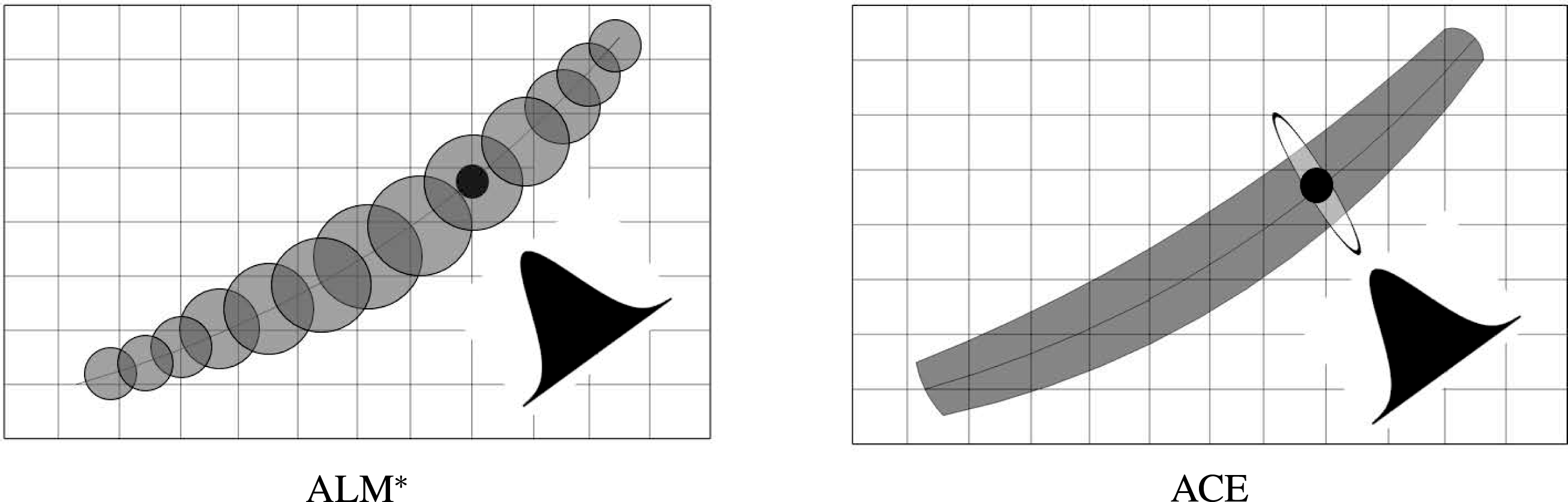
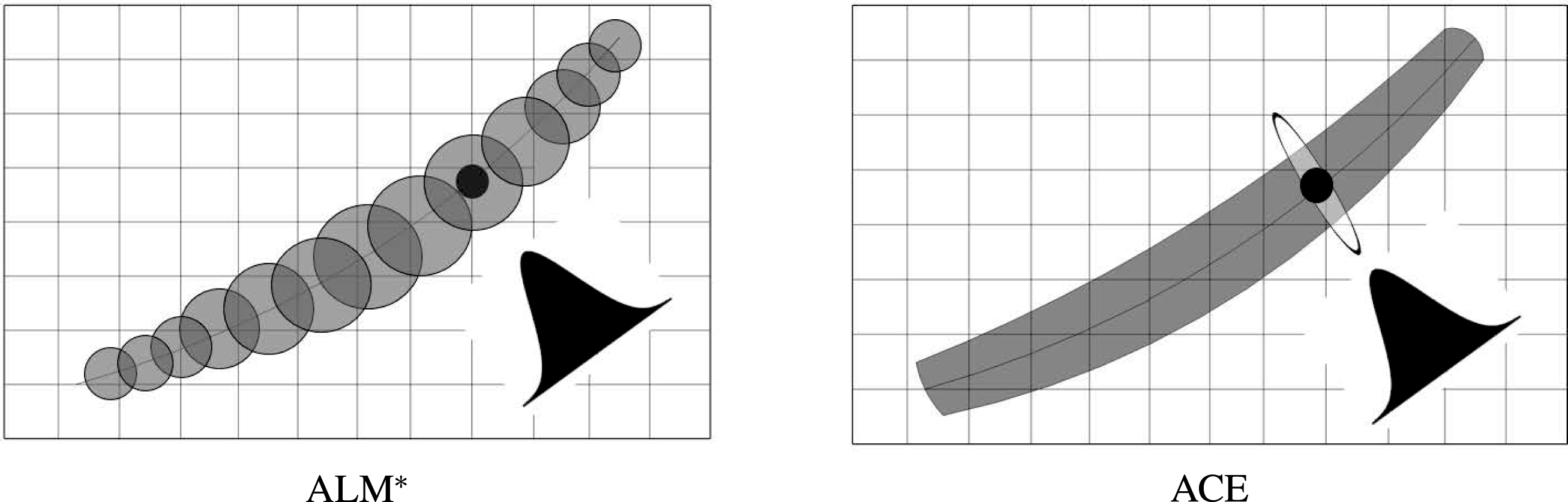
Three-dimensional (ALM
 $^{\ast }$
) versus two-dimensional (ACE) Gaussian kernel function.
3 Actuator curve embedding in OpenFOAM
The conceptual idea of ACE is to remove the inconsistency in force overlap inherent to standard ALM and ASM approaches. This can be achieved if (i) the kernel function is chosen in such a way that the projection of blade forces is circumferential only in the region normal to the local blade section, (ii) each grid point has a unique body force associated with a specific section of an actuator element and (iii) the volume integral of the total projected blade force is conserved. It should be noted that the force overlap is unphysical and can only be controlled by an appropriate spacing between actuator points (Jha et al. Reference Jha, Churchfield, Moriarty and Schmitz2014), and is inconsistent for curved lifting lines (or aeroelastically deforming blades) due to a dynamic overlap region in convex or concave curvature.
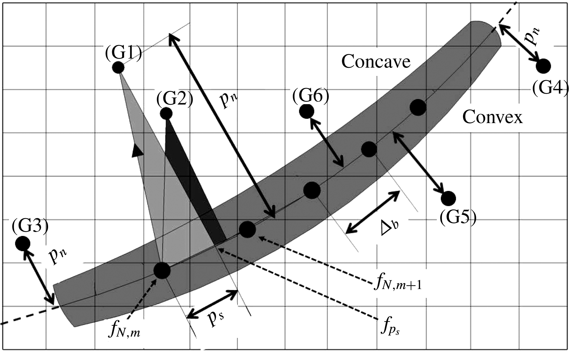
The ACE concept is inspired by the vorticity-embedding methodology due to Steinhoff & Ramachandran (Reference Steinhoff and Ramachandran1988) and subsequent implementation into a Eulerian/Lagrangian free-wake solver for hovering rotorcraft (Schmitz et al. Reference Schmitz, Bhagwat, Moulton, Caradonna and Chattot2009). As opposed to sequentially finding a sphere of influence around each actuator point, a reverse approach is followed in ACE. Here, the flow field experiences the influence of a blade/wing as one entity. This is realized by associating each grid cell with a unique actuator element along the lifting curve, rather than being influenced by multiple actuator points; see figure 2.
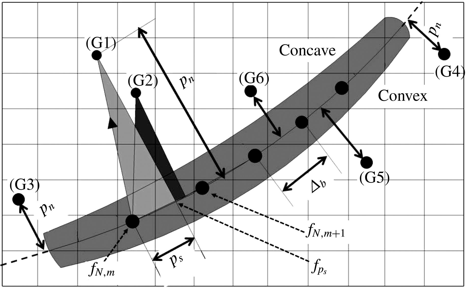
Actuator curve embedding – computation of
 $p_{n}$
and
 $p_{s}$
at each
 $(x_{P},y_{P},z_{P})$
.
3.1 Actuator curve embedding – geometric parameterization
For a given grid point
 $\boldsymbol{r}_{p}=(x_{P},y_{P},z_{P})^{\text{T}}$
, each actuator-element pair
 $m$
and
 $m+1$
has unique values for the tangential coordinate
 $p_{s}$
along the respective actuator element and normal distance
 $p_{n}$
to the actuator element, as shown in figure 3. The tangential coordinate
 $p_{s}$
is normalized by the width of the actuator element,
 $\unicode[STIX]{x1D6E5}_{b}=\Vert \boldsymbol{r}_{N,m+1}-\boldsymbol{r}_{N,m}\Vert$
, between
 $\boldsymbol{r}_{N,m}$
and
 $\boldsymbol{r}_{N,m+1}$
, and is determined by
 $$\begin{eqnarray}p_{s}=\frac{(\boldsymbol{r}_{p}-\boldsymbol{r}_{N,m}).(\boldsymbol{r}_{N,m+1}-\boldsymbol{r}_{N,m})}{\unicode[STIX]{x1D6E5}_{b}^{2}}.\end{eqnarray}$$
A given grid point
 $\boldsymbol{r}_{p}$
is associated with the pair of actuator points
 $m$
and
 $m+1$
for which
 $p_{s}\in [0,1]$
. This simple criterion prevents any body-force spreading beyond the edges of the lifting line, see (G3) and (G4) in figure 3, and associates a given grid cell
 $\boldsymbol{r}_{p}$
with a specific actuator segment, or results in a grid cell not being affected by body-force projection. The corresponding normal distance,
 $p_{n}$
, is then expressed as
 $$\begin{eqnarray}p_{n}=\frac{\Vert (\boldsymbol{r}_{p}-\boldsymbol{r}_{N,m})\times (\boldsymbol{r}_{p}-\boldsymbol{r}_{N,m+1})\Vert }{\unicode[STIX]{x1D6E5}_{b}}.\end{eqnarray}$$
It can be noted from figure 3 that two different grid cells, (G1) and (G2), can be associated with the same pair of actuator points,
 $\boldsymbol{r}_{N,m}$
and
 $\boldsymbol{r}_{N,m+1}$
, but still have unique values for
 $p_{s}$
and
 $p_{n}$
. For a lifting line
 $N$
with curvature, special cases may arise for grid point
 $\boldsymbol{r}_{p}$
facing either the convex (G5) or concave (G6) side,
 $$\begin{eqnarray}\displaystyle & \displaystyle \text{convex:}\quad (p_{s_{m}}>1)\wedge (p_{s_{m+1}}<0)\rightarrow p_{n}=\Vert \boldsymbol{r}_{p}-\boldsymbol{r}_{N,m+1}\Vert ,\quad p_{s}=1; & \displaystyle\end{eqnarray}$$
 $$\begin{eqnarray}\displaystyle & \displaystyle \text{concave:}\quad p_{s_{m}},~p_{s_{m+1}}\in [0,1]~\rightarrow ~p_{n}=\min (p_{n_{m}},p_{n_{m+1}}),\quad p_{s}=p_{s_{m}}\vee p_{s_{m+1}}. & \displaystyle\end{eqnarray}$$
It should be noted that in the concave case,
 $p_{s}$
is chosen from either actuator element
 $m$
or
 $m+1$
depending on the minimum normal distance
 $p_{n}$
, possibly resulting in an index shift
 $m\rightarrow m+1$
. The resulting body force experienced at grid point
 $\boldsymbol{r}_{p}$
becomes
 $\boldsymbol{f}_{p_{s}}$
, which is determined as an interpolated value between
 $\boldsymbol{f}_{N,m}$
and
 $\boldsymbol{f}_{N,m+1}$
through
 $$\begin{eqnarray}\boldsymbol{f}_{p_{s}}=\boldsymbol{f}_{N,m}+p_{s}(\boldsymbol{f}_{N,m+1}-\boldsymbol{f}_{N,m}).\end{eqnarray}$$
Consequently, a continuous, rather than discrete, body-force distribution is obtained along the actuator line, thus allowing quasi-two-dimensional kernel integration normal to the associated actuator line element. This stands in contrast to ALM and ALM*, where each grid cell can be influenced by multiple discrete actuator points and experience cumulative effects. In ACE, on the other hand, each grid cell is influenced by a continuous and unique body force
 $\boldsymbol{f}_{p_{s}}$
, which need not be at a physical actuator point.
3.2 Actuator curve embedding – quasi-two-dimensional kernel integration
A quasi-two-dimensional (2D) Gaussian kernel function is the key element to eliminate both of the non-physical body-force overlap projections beyond the blade tips as seen in the standard ALM or ALM*. It should be noted that this kernel function had been suggested earlier by Mikkelsen (Reference Mikkelsen2003) and more recently by Shives & Crawford (Reference Shives and Crawford2013) for finite span wings. Here, the blade force, including lift and drag forces, is distributed in a disc normal to the local actuator element. Conservation of blade and body forces is satisfied through normalization with the local actuator-element width
 $\unicode[STIX]{x1D6E5}_{b}$
. In this respect, the volumetric Gaussian distribution of the body force in ACE is fundamentally different from that used in the ALM and ALM* implementations. The respective body force per unit volume is computed as
 $$\begin{eqnarray}\boldsymbol{F}_{p}(x_{P},y_{P},z_{P})=-\mathop{\sum }_{N}\frac{1}{\unicode[STIX]{x03C0}\unicode[STIX]{x1D716}^{2}\unicode[STIX]{x1D6E5}_{b}}\boldsymbol{f}_{p_{s}}\exp [-(p_{n}/\unicode[STIX]{x1D716})^{2}],\end{eqnarray}$$
where the summation over the blade index
 $N$
is included for the sole purpose of completeness, for grid points
 $\boldsymbol{r}_{p}$
being located on symmetry planes between lifting lines. It should be noted that the total blade force
 $\boldsymbol{f}_{p_{s}}$
is conserved for the general case of
 $\unicode[STIX]{x1D6E5}_{grid}\neq \unicode[STIX]{x1D6E5}_{b}$
as the force per unit volume
 $\boldsymbol{F}_{p}$
is multiplied by a scaled cell volume
 $\unicode[STIX]{x0394}V^{2/3}\cdot \unicode[STIX]{x1D6E5}_{b}$
when injected into the momentum equation (2.1). Verification tests were conducted for straight as well as curved lifting lines approximated as second- and fourth-order polynomials (Jha Reference Jha2015). A variable Gaussian projection radius
 $\unicode[STIX]{x1D716}(r)$
is determined using
 $$\begin{eqnarray}\text{ACE:}\quad \unicode[STIX]{x1D716}/c^{\ast }=C_{1}(\unicode[STIX]{x03C0}AR)[C_{2}\cdot TSR+C_{3}]\end{eqnarray}$$
as a generalized version of (2.6), where
 $TSR$
is the ratio of lifting-line tip speed to free-stream speed, commonly referred to as the tip-speed ratio. Parametric studies conducted primarily on the NREL Phase VI rotor and analysed by Jha (Reference Jha2015) showed that a weaker
 $TSR$
dependence is necessary due to, as opposed to the parked case, the lifting line not traversing parallel to the sectional relative velocity vector
 $\boldsymbol{V}_{rel}$
. From ALM*,
 $C_{1}\in [0.025,0.030]$
, and
 $C_{2}=0.1410$
,
 $C_{3}=-0.3609$
should be used in conjunction with (3.7) for typical operating conditions of
 $TSR\geqslant 4$
, with
 $C_{2}=0$
and
 $C_{3}=1$
in the case of a parked blade or wing.
4 Results
This section presents validation results for the ACE concept by application to an elliptic wing, the NREL Phase VI rotor and the NREL 5-MW turbine. For all computations, the grid used has a resolution of
 $\unicode[STIX]{x1D6E5}_{grid}=1/32$
of the wing span or blade radius. This was found to be an adequate and computationally efficient grid resolution for actuator line methods (Jha et al.
Reference Jha, Churchfield, Moriarty and Schmitz2014) and underscores the advantage compared with actuator surface methods with respect to the required grid resolution. The solver time step is chosen such that the flow does not convect more than one grid cell per time step at the wing or blade tip. It should be mentioned that in subsequent comparisons, ALM results were mostly obtained without using a tip correction. This was done for the sole purpose of demonstrating the range of actuator line predictions, and hence ALM results without tip correction are not necessarily representative of the best comparisons that can be achieved using ALM.
4.1 Elliptic wing
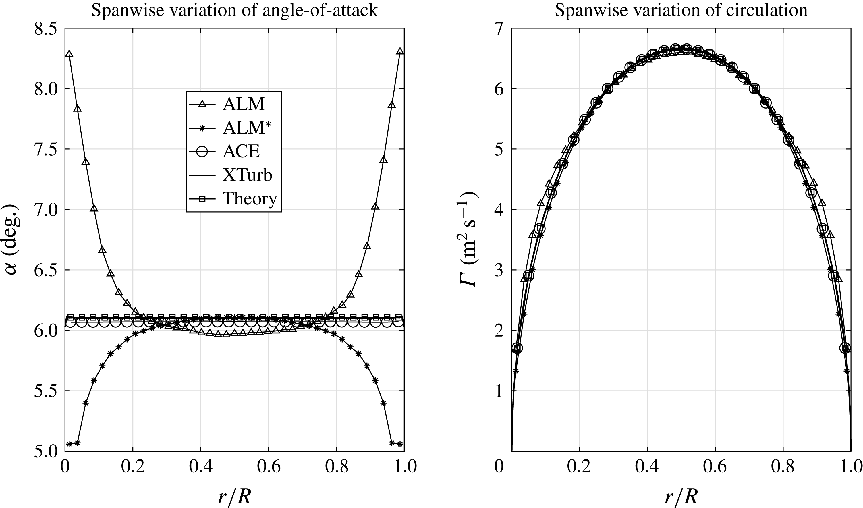
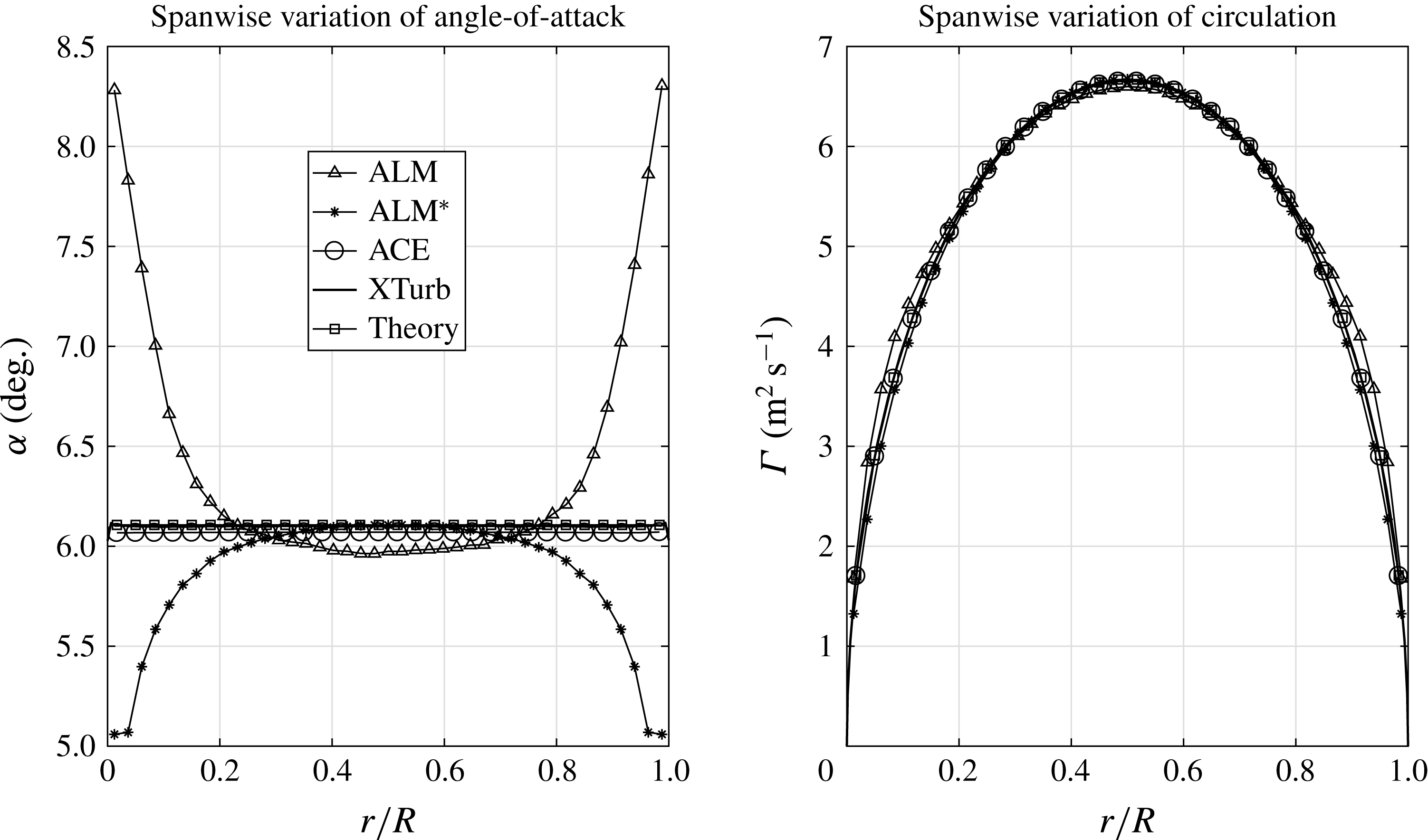
Results obtained for an elliptic wing using ACE are shown in figure 4. The elliptic wing has a span of 5.029 m and an aspect ratio of 8.24. The free-stream wind speed is
 $20.1~\text{m}~\text{s}^{-1}$
and the wing setting angle is
 $8^{\circ }$
. Quantitative comparisons are performed against results obtained by the standard grid-based ALM without tip correction, elliptic Gaussian-based ALM*, the XTurb lifting-line code (Schmitz Reference Schmitz2012) as well as classical theory. The figure shows the induced angle-of-attack and circulation distributions along the wing span. It is of particular note that both ALM and ALM* either over- or underpredict wing tip loads, which is hypothesized to be a consequence of the force overlap between adjacent actuator points and force projection beyond the blade tips, both resulting in a small error in local trailing vorticity, hence downwash at the lifting line and ultimately sectional forces. The ACE concept, on the other hand, removes this fundamental inconsistency and follows closely the exact solution due to classical theory (Milne-Thomson Reference Milne-Thomson1958) over the entire wing span, with a computed induced angle of attack of
 $6.05^{\circ }$
in comparison with the exact solution of
 $6.11^{\circ }$
.
Spanwise angle of attack and circulation for an elliptic wing,
 $V_{\infty }=20.1~\text{m}~\text{s}^{-1}$
(ALM,
 $\unicode[STIX]{x1D716}/\unicode[STIX]{x1D6E5}_{grid}=2$
; ALM*,
 $\unicode[STIX]{x1D716}/c^{\ast }=0.67,\unicode[STIX]{x1D716}_{min}=\unicode[STIX]{x1D6E5}_{grid}$
; ACE,
 $\unicode[STIX]{x1D716}/c^{\ast }=0.7,\unicode[STIX]{x1D716}_{min}=\unicode[STIX]{x1D6E5}_{grid}$
).
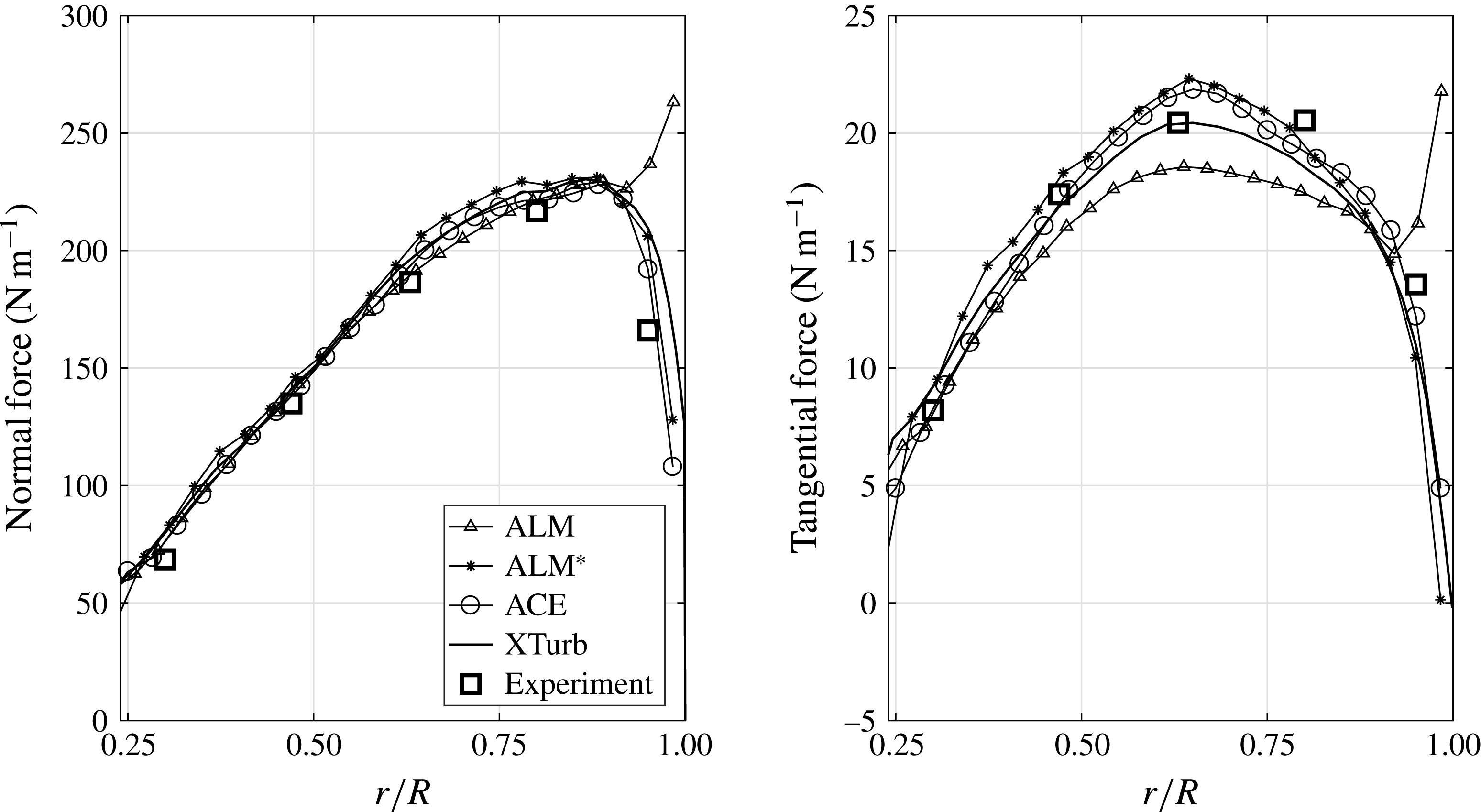
4.2 NREL Phase VI rotor: rotating
This subsection presents results obtained for the NREL Phase VI rotor under rotating conditions (Hand et al.
Reference Hand, Simms, Fingersh, Jager, Cotrell, Schreck and Larwood2001). The free-stream wind speed is
 $7~\text{m}~\text{s}^{-1}$
and the rotor speed is 72 RPM (
 $TSR=5.4$
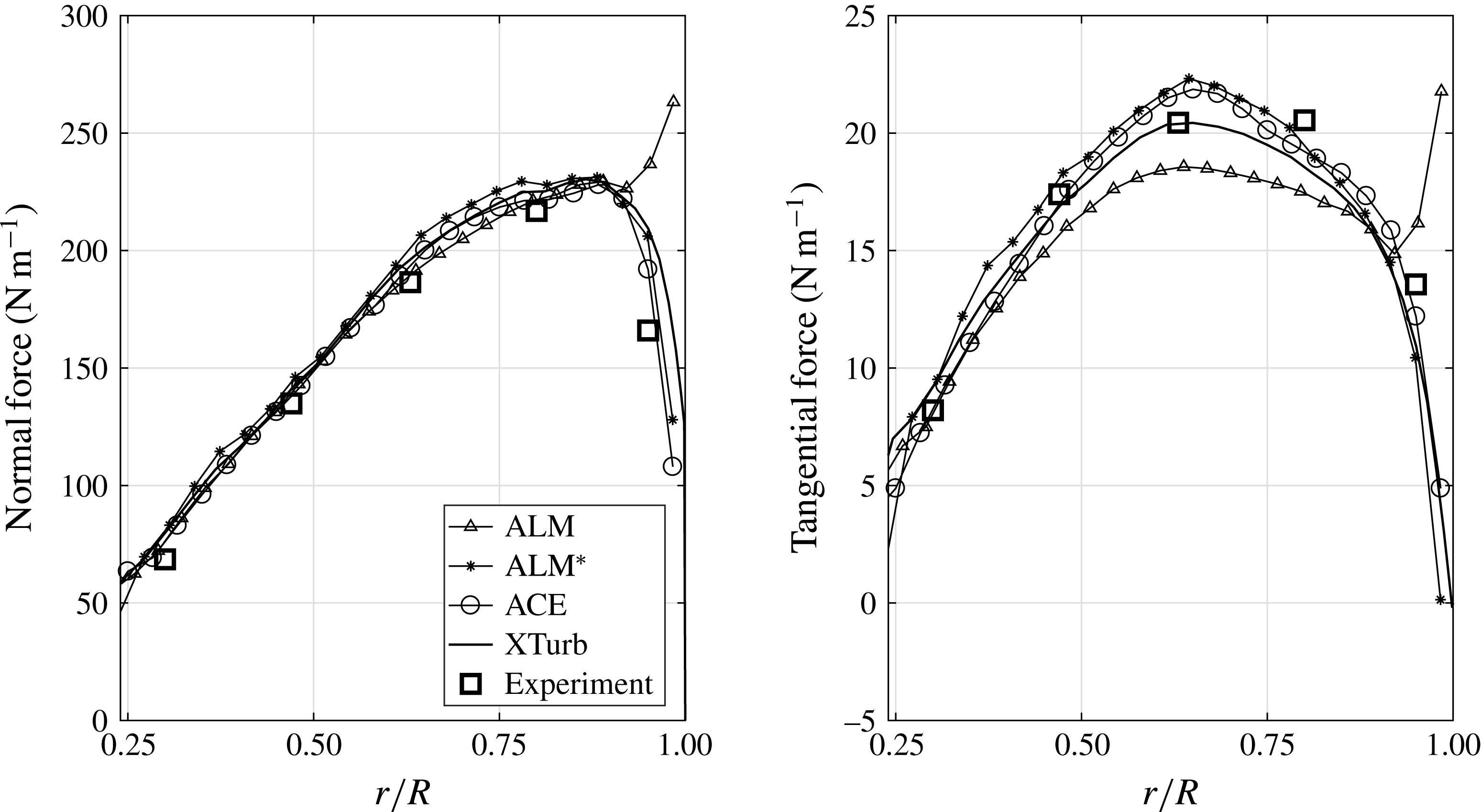
), with the blades having an aspect ratio of 10.5. Figure 5 shows the spanwise variation of normal and tangential force per unit span. The comparisons are made for results obtained with grid-based ALM without tip correction, elliptic Gaussian-based ALM*, ACE, XTurb and measured NREL data (experiment). The ACE results are again in very good agreement with the measured NREL data, with an integrated turbine power of 6180 W (ACE) compared with 6030 W (NREL). It is furthermore noteworthy that both ALM* and XTurb also show good comparisons with measured NREL data, as documented in earlier work (Jha et al.
Reference Jha, Churchfield, Moriarty and Schmitz2014).
Sectional forces on rotating NREL Phase VI rotor,
 $V_{\infty }=7~\text{m}~\text{s}^{-1}$
and
 $\text{RPM}=72$
(ALM,
 $\unicode[STIX]{x1D716}/\unicode[STIX]{x1D6E5}_{grid}=2$
; ALM*,
 $\unicode[STIX]{x1D716}/c^{\ast }=0.67,\unicode[STIX]{x1D716}_{min}=\unicode[STIX]{x1D6E5}_{grid}$
; ACE,
 $\unicode[STIX]{x1D716}/c^{\ast }=0.4$
,
 $\unicode[STIX]{x1D716}_{min}=\unicode[STIX]{x1D6E5}_{grid}$
).
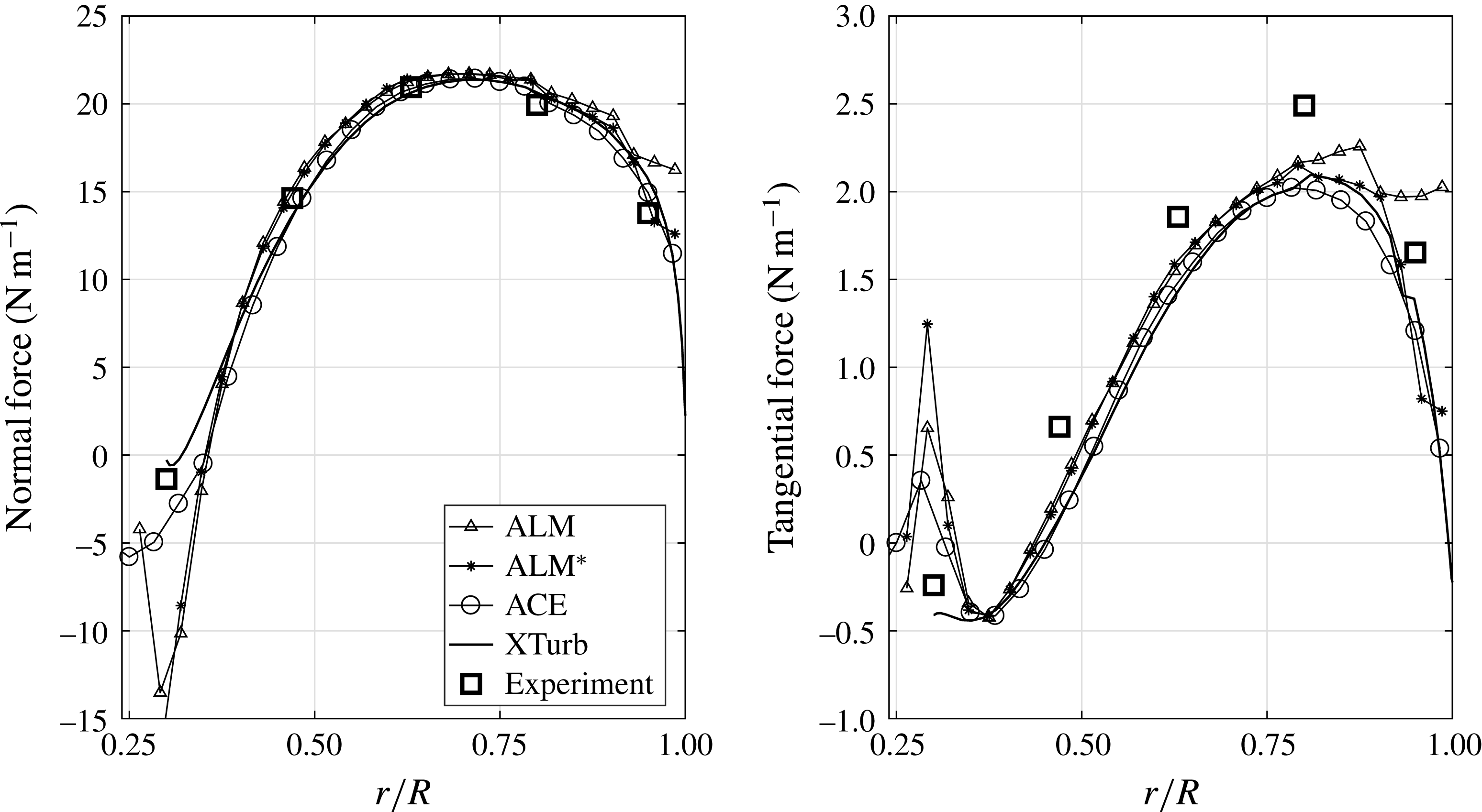
4.3 NREL Phase VI rotor: parked
Results obtained for the parked NREL Phase VI rotor (Hand et al.
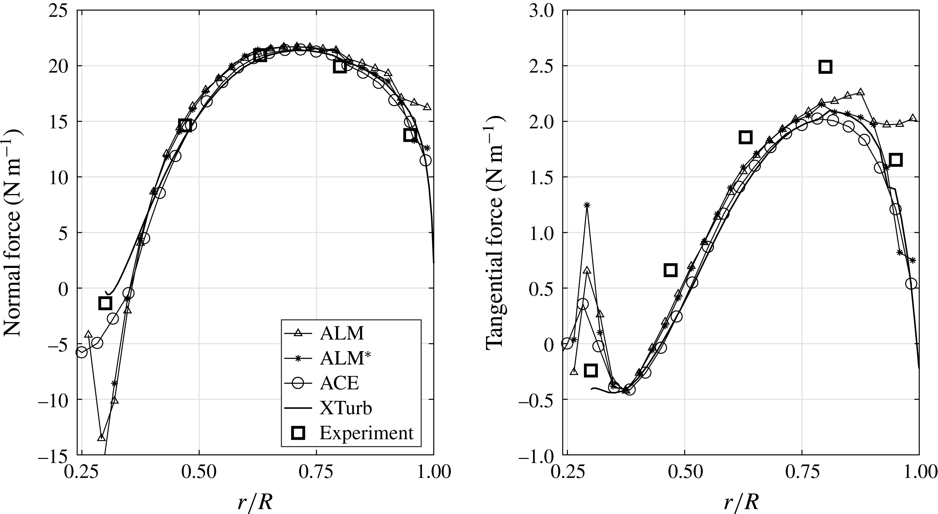
Reference Hand, Simms, Fingersh, Jager, Cotrell, Schreck and Larwood2001) are shown in figure 6. The free-stream wind speed is
 $20.1~\text{m}~\text{s}^{-1}$
and the pitch is
 $81.59^{\circ }$
. In figure 6, the spanwise variation of normal and tangential force coefficients is shown. Similarly to the elliptic wing and the NREL Phase VI rotor under rotating conditions, comparisons are conducted with results obtained with grid-based ALM without tip correction, elliptic Gaussian-based ALM*, ACE, XTurb and measured NREL data. The parked NREL Phase VI rotor is a challenging test case of two interacting twisted and tapered finite span wings. It is noteworthy that ACE predicts both root and tip loads very well.
Sectional forces on parked NREL Phase VI rotor,
 $V_{\infty }=20.1~\text{m}~\text{s}^{-1}$
(ALM,
 $\unicode[STIX]{x1D716}/\unicode[STIX]{x1D6E5}_{grid}=2$
; ALM*,
 $\unicode[STIX]{x1D716}/c^{\ast }=0.67,\unicode[STIX]{x1D716}_{min}=\unicode[STIX]{x1D6E5}_{grid}$
; ACE,
 $\unicode[STIX]{x1D716}/c^{\ast }=1.0,\unicode[STIX]{x1D716}_{min}=\unicode[STIX]{x1D6E5}_{grid}$
).
4.4 NREL 5-MW turbine
The NREL 5-MW turbine is a conceptual large utility-scale wind turbine designed by NREL (Jonkman et al.
Reference Jonkman, Butterfield, Musial and Scott2009) with a blade aspect ratio of 18.1. Here, a free-stream wind speed of
 $8~\text{m}~\text{s}^{-1}$
and a rotor speed of 9.16 RPM (
 $TSR=7.6$
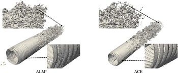
) are considered. Figure 7 shows the wake for the NREL 5-MW turbine using ALM* and ACE. Only small differences can be seen in both tip vortices and wakes.
Isosurface (
 $\unicode[STIX]{x1D714}=0.5~\text{s}^{-1}$
) for NREL 5-MW turbine,
 $V_{\infty }=8~\text{m}~\text{s}^{-1}$
and
 $\text{RPM}=9.16$
(ALM*,
 $\unicode[STIX]{x1D716}/c^{\ast }=1.33,\unicode[STIX]{x1D716}_{min}=\unicode[STIX]{x1D6E5}_{grid}$
; ACE,
 $\unicode[STIX]{x1D716}/c^{\ast }=1.2,\unicode[STIX]{x1D716}_{min}=\unicode[STIX]{x1D6E5}_{grid}$
).

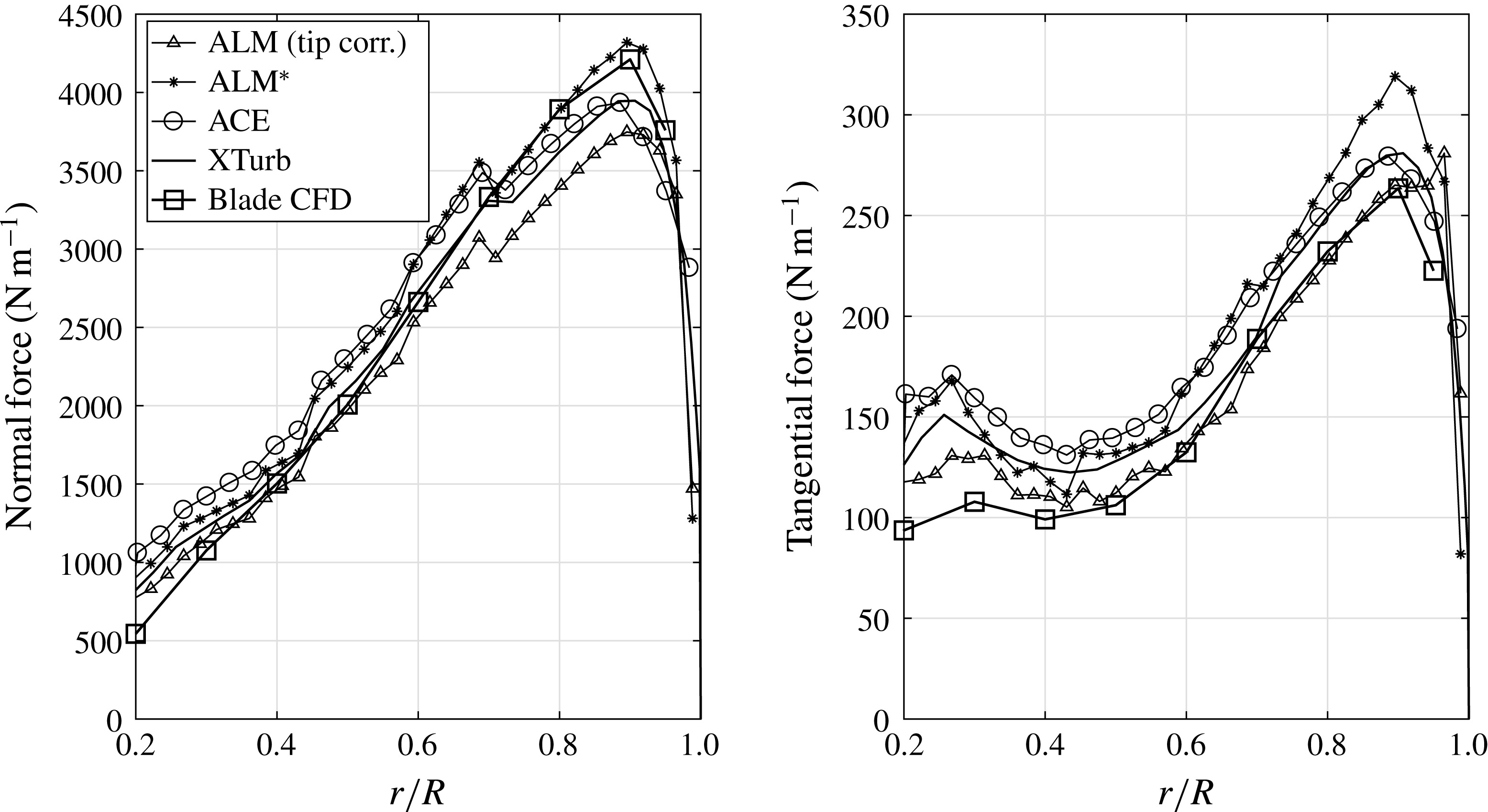
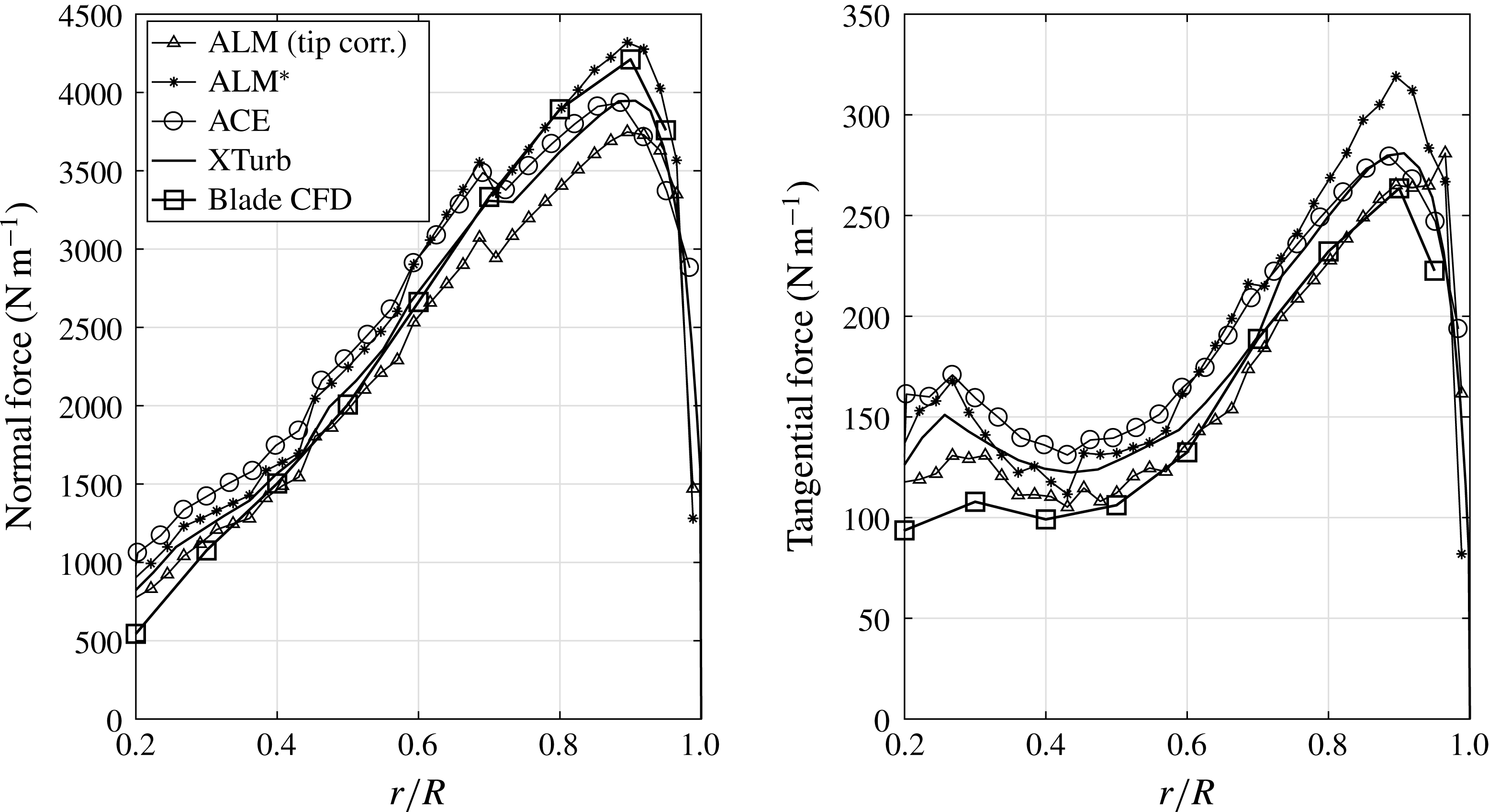
Quantitative comparisons are made with results obtained with ALM (with tip correction), ALM* and XTurb, and CFD results documented in Chow & van Dam (Reference Chow and van Dam2012). It should be noted that experimental data are not available for this turbine. Figure 8 shows the spanwise variation of normal and tangential force per unit span. It should be noted that, apart from CFD, all other methods exhibit small jumps in sectional force distributions at the respective aerofoil breakpoints. It can be observed that the ACE results (1953 kW power) are consistent with those computed by XTurb (1854 kW power) and by high-fidelity CFD (1733 kW power), noting that the latter includes overset grids around the turbine hub and has an additional documented
 $\pm 5\,\%$
uncertainty with respect to steady versus time-accurate simulations and computational grids in the turbine wake (Chow & van Dam Reference Chow and van Dam2012). The comparisons emphasize once more the predictive capability of the ACE concept.
Sectional forces on rotating NREL 5-MW rotor,
 $V_{\infty }=8~\text{m}~\text{s}^{-1}$
and
 $\text{RPM}=9.16$
(ALM,
 $\unicode[STIX]{x1D716}/\unicode[STIX]{x1D6E5}_{grid}=2$
; ALM*,
 $\unicode[STIX]{x1D716}/c^{\ast }=1.33,\unicode[STIX]{x1D716}_{min}=\unicode[STIX]{x1D6E5}_{grid}$
; ACE,
 $\unicode[STIX]{x1D716}/c^{\ast }=1.2$
,
 $\unicode[STIX]{x1D716}_{min}=\unicode[STIX]{x1D6E5}_{grid}$
).
5 Conclusion
The ACE concept removes a fundamental inconsistency in actuator line modelling by eliminating both force overlap on the actuator line and force projection beyond the blade tips. Quantitative validation studies were performed for an elliptic wing, the NREL Phase VI rotor in rotating and parked conditions, and the NREL 5-MW turbine. Hence, variations in operating conditions (parked versus rotating), wing/blade planform and tip shapes, blade aspect ratio and blade number were studied. In general, ACE performs similarly to the advanced ALM* method, demonstrating more generality for a classical elliptic wing case and parked turbine blades. It is concluded that the ACE concept is well validated, applicable to any body-force type method and of importance to future studies on flexible wind turbine blades and wind farm dynamics.