Introduction
Hitachiite, Pb5Bi2Te2S6, is a new mineral discovered in the Hitachi mine, Ibaraki Prefecture, Japan. The chemical formula of hitachiite is plotted on the join of Bi2Te2S (tetradymite)–PbS (galena) in the system Bi–Pb–(Te, S). The join also includes aleksite (PbBi2Te2S2) and saddlebackite (Pb2Bi2Te2S3), which belong to the tetradymite group of minerals in the 9th edition of the Strunz mineral classification system (Strunz and Nickel, Reference Strunz and Nickel2001). The mineral and its name have been approved by the Commission on New Minerals, Nomenclature and Classification of the International Mineralogical Association (IMA2018-027, Kuribayashi et al., Reference Kuribayashi, Nagase, Nozaki, Ishibashi, Shimada, Shimizu and Momma2018). The type specimen of hitachiite is deposited under catalogue number NSM-M45821 in the National Museum of Nature and Science, Tsukuba, Ibaraki Prefecture, Japan.
The crystal structures of the tetradymite group of minerals can be considered as combinations of several structural units. Bindi and Cipriani (Reference Bindi and Cipriani2003) investigated Pb-enriched baksanite (Bi5Pb)Te2S3; baksanite, Bi6Te2S3, is one of the tetradymite group of minerals), and reported that its crystal structure can be described as an alternation of modules of an ingodite-type structure (Bi2TeS) and of a joséite-A-type structure (Bi4TeS2). Similarly, hitachiite can be considered as a homologous series of PbnBi4Te4Sn+2 in the Pb–Bi tellurosulfides proposed by Cook et al. (Reference Cook, Ciobanu, Stanley, Paar and Sundblad2007a,Reference Cook, Ciobanu, Wagner and Stanleyb). The general formula has been reviewed by Moëlo et al. (Reference Moëlo, Makovicky, Mozgova, Jambor, Cook, Pring, Paar, Nickel, Graeser, Karup–Moøller, Balic–Žunic, Mumme, Vurro, Topa, Bindi, Bente and Shimizu2008) as Pb(n–1)Bi2Ch (n+2) (Ch = Te, Se and S) on the basis of the tetradymite archetype. It is therefore important to determine the crystal structure of hitachiite in order to classify it in the tetradymite group of minerals. The discovery of hitachiite presents the possibility of forming a homologous series with aleksite and saddlebackite, expressed as Bi2Te2S·nPbS. As the crystal structures of aleksite and saddlebackite have not been determined so far, determining the structure of hitachiite could help in understanding the structural and crystal chemistry of minerals in the system Bi2Te2S–PbS. In this report, we present the structure of hitachiite refined using single-crystal synchrotron X-ray diffraction data.
Occurrence and appearance
Hitachiite was discovered at the Hitachi mine, located in the city of Hitachi, Ibaraki Prefecture, Japan (36°37'16.03″N, 140°36′46.50″E). The Hitachi mine comprises Fudotaki and Fujimi deposit groups, with the aforementioned Fudotaki deposit being one of the representative orebodies of the Fudotaki group (Kase and Yamamoto, Reference Kase and Yamomoto1985). The Fudotaki deposit is classified as a volcanogenic massive sulfide (VMS) deposit and a Cu–Zn sulfide deposit with small amounts of Pb. The Fudotaki sulfide ores have been metamorphosed into lower epidote–amphibole facies via regional metamorphism. The primary formation age of the Fudotaki deposit was estimated to have been formed during the Cambrian period. The Fudotaki deposit is recognised as the oldest dated ore deposit in Japan by both zircon U–Pb radiometric determinations and Re–Os isotope isochron methods (Tagiri et al., Reference Tagiri, Dunkley, Adachi, Hiroi and Fanning2011; Nozaki et al. Reference Nozaki, Kato and Suzuki2014).
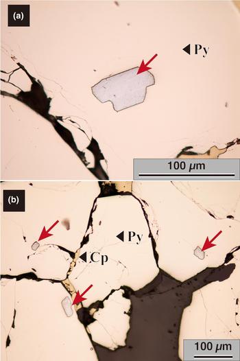
Emeritus Prof. K. Kase of Okayama University collected samples (including hitachiite) from the Fudotaki deposit at Hitachi mine to investigate geochemically its mineralisation and metallogenesis (Kase, Reference Kase1978; Kase and Yamamoto, Reference Kase and Yamomoto1985). Hitachiite crystals occur as tiny grains within pyrite crystals (Fig. 1a,b) and are commonly found with pyrite, chalcopyrite, minor amounts of sphalerite and pyrrhotite and very minor amounts of galena and marcasite. The individual grains are ~10–100 µm in size.
Optical reflected light microscopy images of hitachiite: (a) magnified image of a hitachiite grain; and (b) hitachiite found commonly in pyrite. Holotype specimen, catalogue number NSM-M45821.

Optical and physical properties
The polished section including abundant hitachiite crystals were made using the type specimen with catalogue number NSM-M45821. Hitachiite is an opaque mineral with a metallic lustre and black streak. The macroscopic colour of hitachiite is silver grey. Polished specimens of hitachiite reveal that its bireflectance is weak with no observable pleochroism; its anisotropy is weak and no internal reflections are shown. Hitachiite has a Mohs’ hardness of 2½–3. Its calculated density is 7.54 g/cm3 when using the empirical chemical formula and structural data (Z = 1).
Reflectance data
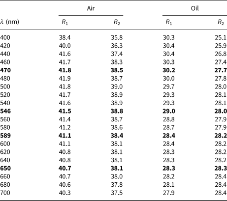
After optical observations, reflectance measurements were conducted on selected hitachiite crystals within the polished section. Reflectance measurements for hitachiite were performed against a WC009 standard material, which had been measured relative to a WTiC (Zeiss 314) by the late A.J. Criddle. Immersion measurements were performed using Nikon oil (N D = 1.515) at room temperature (20°C). A Nikon Optiphot-2 microscope photometer with a Nikon photometer-head-measurement-finder, a Nikon photometer controller P101, a Nikon monochromator G-70 and a Nikon two-light-flux interference examination installed at the University of Toyama were used for these measurements. The reflectance data are summarised in Table 1
Reflectance data (R 1 and R 2 in %) in air and oil of hitachiite.

The values required by the Commission on Ore Mineralogy are given in bold.
Chemical data
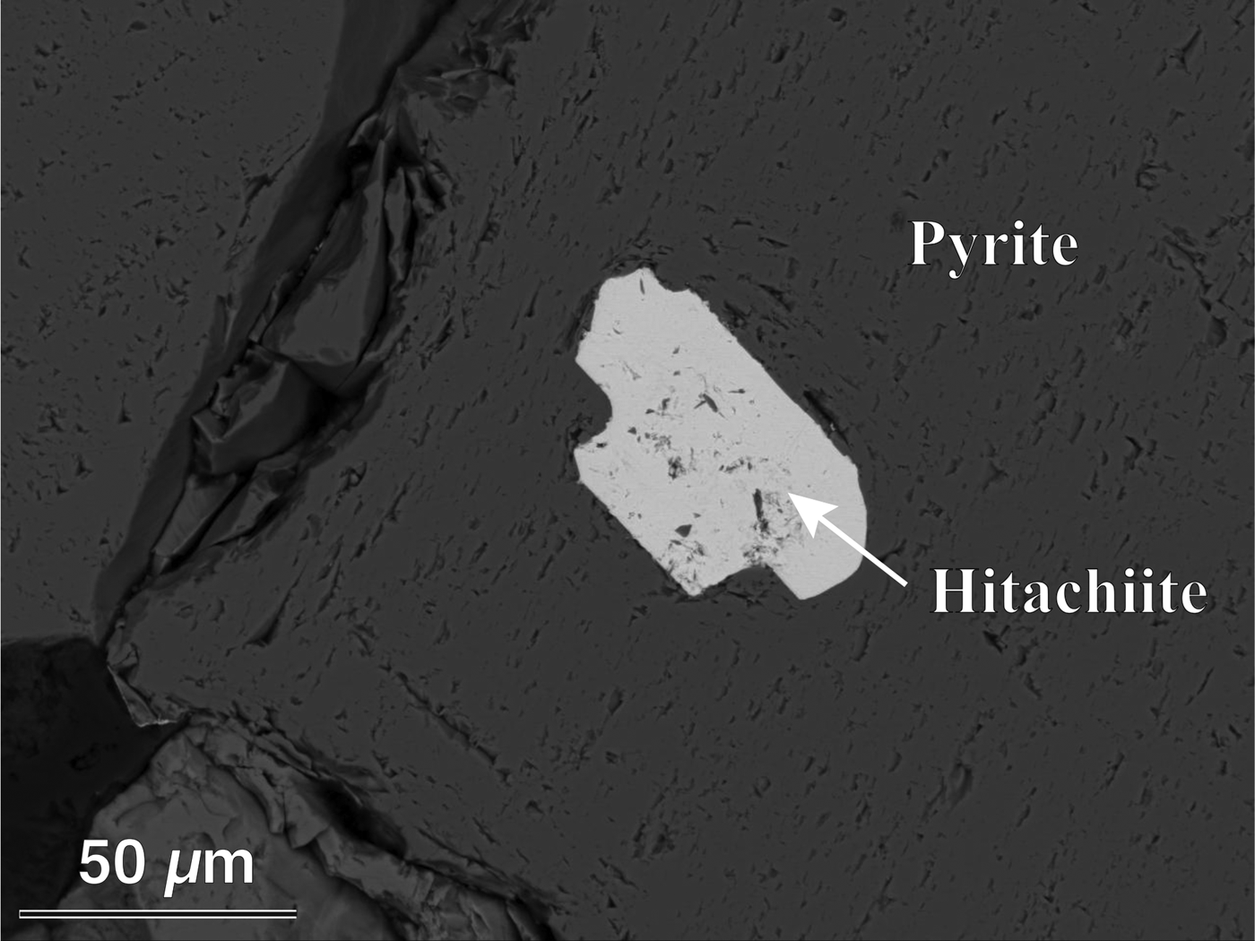
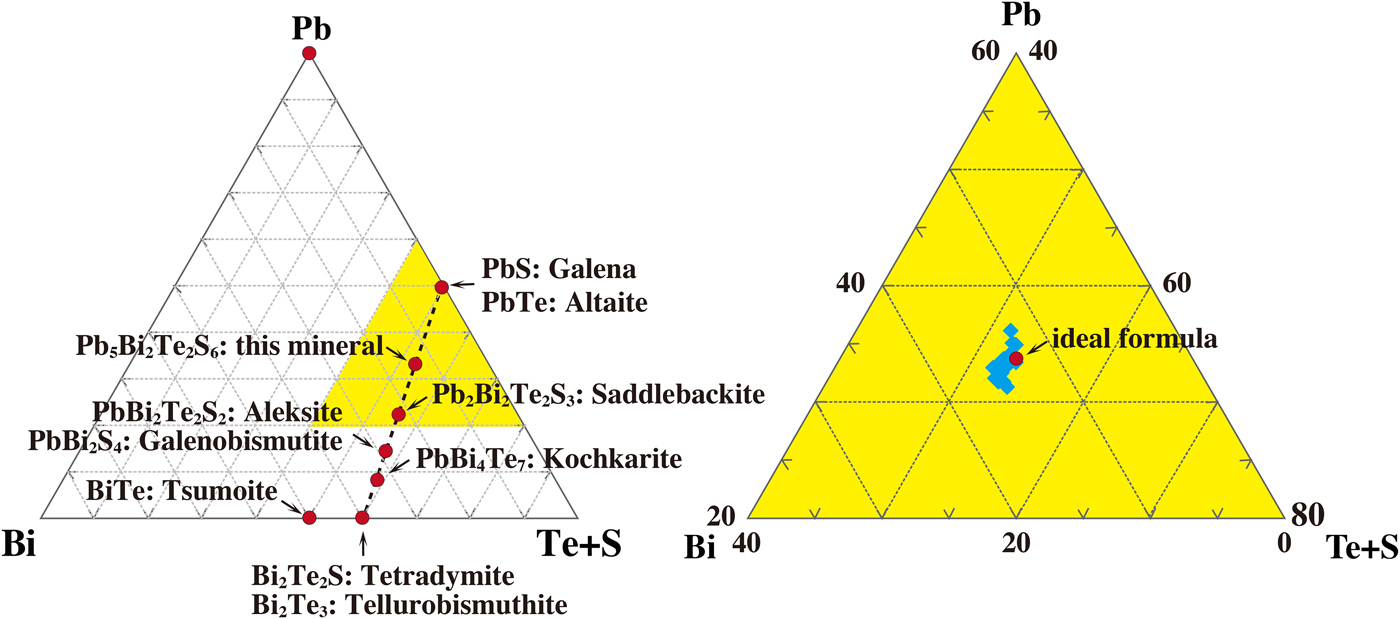
The composition of hitachiite was obtained using a field emission electron probe micro-analyser (JEOL, JXA-8530F) at Kyushu University, under operating conditions of 20 kV and 10 nA with a beam diameter of 0.1 µm. Counting time was set at 40 s for each element. Standard materials used to quantitatively analyse the samples were: galena for Pb; bismuthinite for Bi; Sb2Te3 for Te; pyrite for Fe and S; stibnite for Sb; and In2Se3 for Se. The measured X-ray intensities were corrected using the ZAF method. Although the compositions of some samples are slightly different, no chemical zoning was observed in hitachiite grains (Fig. 2). One-point analysis was conducted per hitachiite crystal within the polished section used for optical observation and reflectance measurement, and the results of 21 analyses are summarised in Supplementary Table S1 (see below); these results yield hitachiite's empirical formula of (Pb4.75Fe0.23)Σ4.98(Bi2.09Sb0.03)Σ2.12Te2.04(S5.73Se0.13)Σ5.86 based on 15 atoms per formula unit. The ideal chemical formula for hitachiite is Pb5Bi2Te2S6. The chemical formula of hitachiite lies on the join of Bi2Te2S–PbS (Fig. 3a).
Back-scattered electron image of a hitachiite grain. Holotype specimen, catalogue number NSM-M45821.

Chemical properties of hitachiite and related minerals: (a) the minerals on the tetradymite–galena join in the system Pb–Bi–(Te + S); and (b) the compositional variation of hitachiite (shown by the blue area).

Crystallography
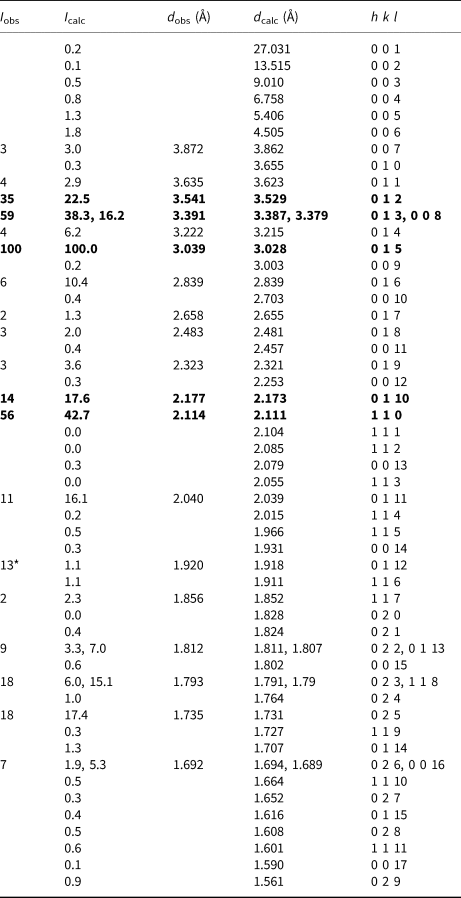
The powder X-ray diffraction (PXRD) pattern of hitachiite was obtained using a Gandolfi camera with a diameter of 114.6 mm and Ni-filtered CuKα radiation (λ = 1.54187 Å) installed at the National Museum of Nature and Science. The data were recorded on an imaging plate and processed through a Fuji BAS-2500 bio-image analyser using computer software written by Nakamuta (Reference Nakamuta1999). The sample used for the PXRD experiment was the same as that used for single-crystal XRD experiment. The PXRD profile of hitachiite and its peak information are shown in Supplementary Fig. S1 and Table 2, respectively. The four strongest diffraction peaks shown in the powder X-ray pattern [d, in Å, (I rel.), (hkl)] are: 3.541 (35) (012), 3.391 (59) (013), 3.039 (100) (015) and 2.114 (56) (110). The diffraction positions were calibrated using silicon as an internal standard. The reflections were indexed by reference to simulated patterns based on the refined crystal structure. The lattice parameters obtained from PXRD are a = 4.2292(12) Å, c = 27.069(8) Å and V = 419.3(3) Å3.
Powder X-ray data with normalised (d in Å) and calculated intensity of hitachiite.
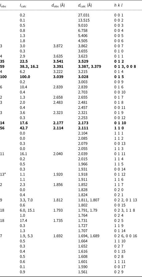
* This diffraction peak was overlapped with peaks of pyrite. Theoretical powder data are calculated on the basis of the structural model refined by single-crystal X-ray diffraction analysis using a four-circle diffractometer.
Single-crystal XRD experiments were conducted using an automated four-circle X-ray diffractometer with synchrotron radiation at the beam line BL-10A, Photon Factory, High Energy Accelerator Research Organisation, KEK, Japan. The wavelength (λ = 0.70134 Å) of synchrotron radiation was calibrated using the obtained unit-cell volume of the ruby standard material (NIST-SRM-1990). In the X-ray oscillation photographs, most of the samples showed diffused and/or streak reflections due to its structural stacking sequence, therefore, a fragment of hitachiite was selected carefully to determine the crystal structure (Fig. 4). The dimension of the sample is ~0.05 mm × 0.02 mm × 0.02 mm, with a chemical formula of (Pb4.60Fe0.25)Σ4.85(Bi2.24Sb0.02)Σ2.26Te2.15(S5.62Se0.13)Σ5.75 (No. 5-2 in Table S1). The lattice parameters were determined as follows: a = 4.2200(13) Å, c = 27.02(4) Å and V = 416.7(7) Å3, based on the 80 centred reflections in the 2θ range 19.1–36.4°. These values are in good agreement with those obtained by PXRD. The X-ray diffraction intensity data were collected up to 2θmax = 60° using a scintillation type detector. Double the unique reciprocal region was measured to check the Laue group. The intensity distribution indicates characteristics of the Laue group  ${\bar 3}$m1. The absorption coefficient (μ) of the hitachiite sample is 71.7 mm–1. Refdelf type absorption correction (XABS2; Parkin et al., Reference Parkin, Moezzi and Hope1995) was applied to our dataset using the WinGX software (Farrugia, Reference Farrugia1999). The value of R int was decreased from 10.8% to 8.6% after the correction. As no systematic absences were observed in the measured intensities, the space group of hitachiite was expected to be P
 ${\bar 3}$m1, P3m1 or P321. The crystal structure of hitachiite was solved against these space groups via the charge-flipping method (Oszlanyi and Suto, Reference Oszlanyi and Suto2004) using the SUPERFLIP software (Palatinus and Chapuis, Reference Palatinus and Chapuis2007). As a result, the P
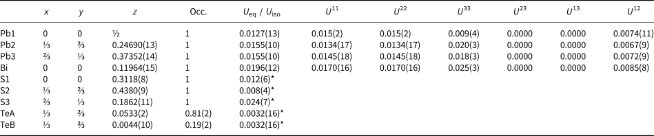
 ${\bar 3}$m1 structural model was shown to be eventually most suitable. The atom positions were obtained by inspecting the electron density distributions, and three Pb, one Bi, one Te and three S sites being assigned. The site for the Bi atom was assigned to form a Te–Bi–S stacking sequence, with reference to the possible sequence of several synthesised phases as proposed by Liu and Chang (Reference Liu and Chang1994) and Cook et al. (Reference Cook, Ciobanu, Stanley, Paar and Sundblad2007a,Reference Farrugiab). The neutral X-ray scattering factors taken from the International Tables for Crystallography Volume C (Prince, Reference Prince2004) were applied in the structure refinement. As distinguishing between Pb and Bi is difficult owing to their similar scattering factors, the metal sites were considered to be occupied by one kind of atom (Pb or Bi). Based on the chemical formula of the examined sample, we considered that a small amount of Fe, Sb and Se were accommodated at Pb, Bi and S sites, respectively. Excess contents of Bi and Te were also divided into Pb and S sites, respectively. Anisotropic displacement factors were applied to Pb and Bi sites, whereas isotropic displacement factors were applied to Te and S sites. An additional site in the interlayer of Te–Te was found after performing a difference-Fourier calculation of the examined sample; this additional site was designated as the TeB site. TeA and TeB sites were too close to be occupied simultaneously. Constraints for the site occupancy and the isotropic displacement factor were applied to these sites as follows: (1) the summation of the occupancy of TeA and TeB is equal to 1; (2) U TeA is equal to U TeB. As this TeB site and another set of residual peaks could be caused by poor crystal quality, such as stacking faults due to chemical variation, we considered that the ideal structure of hitachiite may not possess this site. The residual R value was converged to 9.76% (no absorption correction). After the XABS2 absorption correction, it was improved to 7.38%. All calculations of our structural refinements were performed using SHELXL97 (Sheldrick and Schneider, Reference Sheldrick and Schneider1997) with WinGX crystallographic software (Farrugia, Reference Farrugia1999). The calculated powder X-ray intensities obtained from this structural model are in good agreement with the measured data (Table 2). Miscellaneous information on data collections are summarised in Table 3 and the final atomic coordinates and anisotropic displacement factors are listed in Table 4. Information on selected interatomic distances in the hitachiite structure are summarised in Table 5. Drawings of each structure were produced using VESTA 3 (Momma and Izumi, Reference Momma and Izumi2011). The crystallographic information files have been deposited with the Principal Editor of Mineralogical Magazine and are available with the Supplementary material.
X-ray oscillation photo of hitachiite taken using synchrotron X-ray radiation with imaging plate. The oscillation angle is ~10°.

Detailed information on data collection and structural refinement.

Final atomic coordinates and displacement factors for hitachiite.

* U iso.
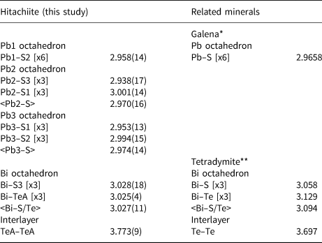
Selected bond distances (Å) in hitachiite with several reference data.

*Data from Noda et al. (Reference Noda, Masumoto, Ohba, Saito, Toriumi, Iwata and Shibuya1987); **Data from Harker et al. (Reference Harker1934)
Crystal structure and its relation to other known phases
The ideal composition of hitachiite is Pb5Bi2Te2S6 and it could be regarded as (Pb5Bi2)Σ7(Te2S6)Σ8, which corresponds to the tetradymite group (2.DC.05) in the 9th edition of the Strunz mineral classification system (Strunz and Nickel, Reference Strunz and Nickel2001). Makovicky (Reference Makovicky and Vaughan2006) summarised the crystal structures of sulfide and related chalcogenide compounds. In his summary, the tetradymite series especially, is expressed chemically as the extended selenides and tellurides of bismuth based on the structural classification of Bayliss (Reference Bayliss1991). The fundamental structural unit of the tetradymite structure has an octahedral double layer Bi2X 3 (X = Te, Se and S). Considering the high amount of Pb in the chemical formula of hitachiite, it seems to be similar to the lillianite (Pb3Bi2S6) series in 2.JA.20 and/or the galenobismutite (PbBi2S4) series in 2.JA.25 of sulfosalts (Strunz and Nickel, Reference Strunz and Nickel2001). However, the crystal structure of hitachiite is definitely different from those of lillianite and galenobismutite, and so it cannot be classified to these groups.
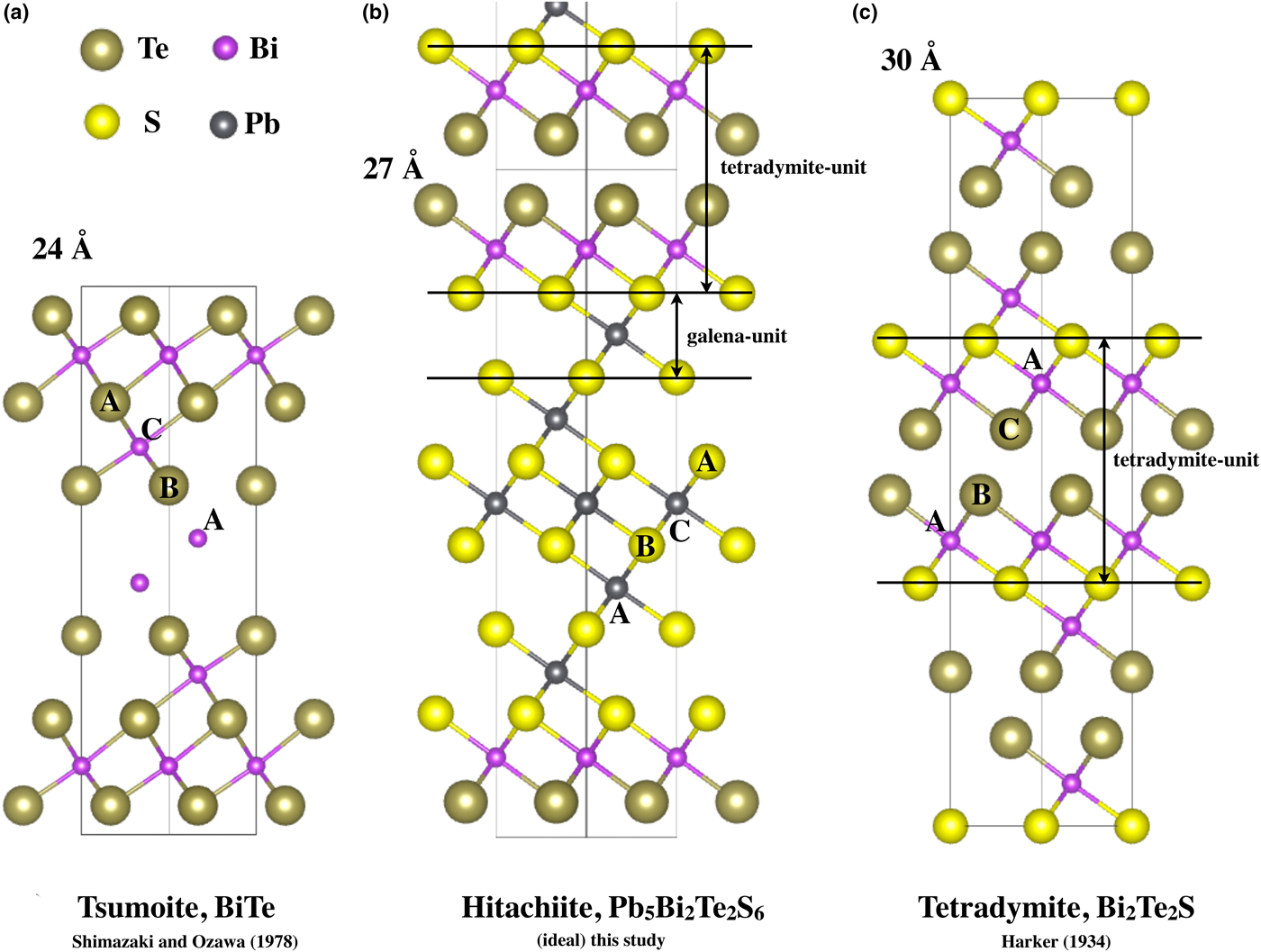
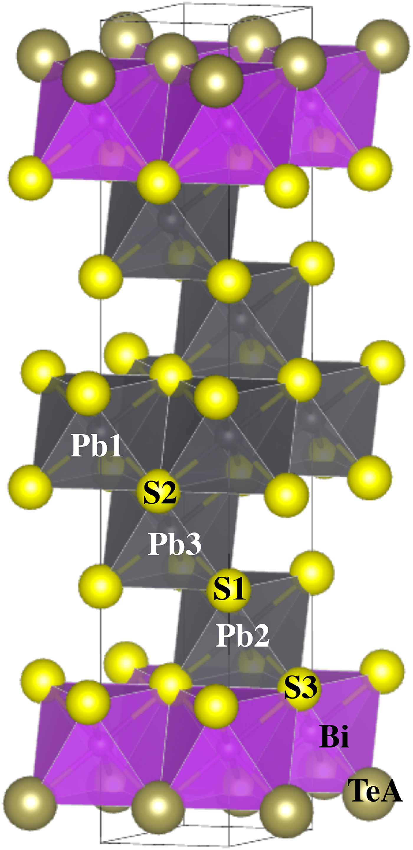
The crystal structure of hitachiite is based on ABC-type close-packing of each single element atomic sheet stacked along the c axis and can be regarded as a layered structure (tetradymite archetype) with a periodicity of ~27 Å. The crystal structure of hitachiite has five Pb, two Bi, two Te and six S sheets. There are three Pb, one Bi, one Te and three S crystallographic sites. The stacking sequence can be expressed as Te–Bi–S–Pb–S–Pb–S–Pb–S–Pb–S–Pb–S–Bi–Te (Fig. 5). The crystal structure of hitachiite contains PbS6 and BiTe3S3 octahedra. Its crystal structure can be viewed as composed from a galena and tetradymite unit (Bi2Te2S) (Figs 5 and 6). The mean Pb–S and Bi–(Te, S) distances in each octahedron are 2.958(14) Å for Pb1–S, 2.970(16) Å for Pb2–S, 2.974(14) Å for Pb3–S and 3.027(11) Å for Bi–(Te, S). These values are in good agreement with those observed in tetradymite (3.058 Å for Bi–S and 3.129 Å for Bi–Te; Harker et al., Reference Harker1934) and that in galena (2.9658(8) Å for Pb–S; Noda et al., Reference Noda, Masumoto, Ohba, Saito, Toriumi, Iwata and Shibuya1987). Also, the TeA–TeA interlayer distance is 3.773(9) Å and is consistent to those of tetradymite (3.697 Å for Te–Te, Harker et al., Reference Harker1934; 3.895–4.037 Å for Te–Te and Te–S, Pauling, Reference Pauling1975) and the reported distance (3.65–3.70 Å for Te–Te) by Makovicky (Reference Makovicky and Vaughan2006).
Crystal structures of hitachiite and related minerals: (a) tsumoite, BiTe; (b) hitachiite, Pb5Bi2Te2S6; and (c) tetradymite, Bi2Te2S.

Ideal structure of hitachiite illustrated using galena-like and tetradymite-like structural units.
In comparison with the tsumoite (BiTe; P  ${\bar 3}$m1; Shimazaki and Ozawa, Reference Shimazaki and Ozawa1978) and the Pb-rich baksanite (Bi5PbTe2S3; P
 ${\bar 3}$m1; Bindi and Cipriani, Reference Bindi and Cipriani2003) structures, hitachiite and tetradymite (Bi2Te2S; R
 ${\bar 3}$; Harker et al., Reference Harker1934) structures lack the Bi–Bi double layer (Fig. 5). As shown by Nakajima (Reference Nakajima1963), in selenides and tellurides of bismuth, there are four species with the tetradymite archetype structure as Bi2TexSe3–x (x = 0, 1, 2 and 3). In contrast, Kuznetsov and Kanishcheva (Reference Kuznetsov and Kanishcheva1970) showed that the compositional limit of tetradymite in the system Bi2Te3–Bi2S3 was Bi2STe2–Bi2S1.3Te1.7. Considering the Te–S substitution, Pauling (Reference Pauling1975) suggested that a partial Te–S interlayer could be allowed in the tetradymite structure. In order to form the tetradymite archetype structure, it is key to have tetradymite unit (S–Bi–Te–Te–Bi–S), which has an anion–anion interlayer except for S–S (Fig. 5). Other related Pb-bearing minerals with tetradymite archetype structure include rucklidgeite, PbBi2Te4 (Zhukova and Zaslavskii, Reference Zhukova and Zaslavskii1972) and kochkarite, PbBi4Te7 (Talybov and Vainshtein, Reference Talybov and Vainshtein1962; Shelimova et al., Reference Shelimova, Karpinski, Svechnikova, Avilov, Kretova and Zemskov2004). However, contrary to that, crystal structures of galenobismutite and mozgovaite, PbBi4S7 are different. These structural differences imply that it is important to consider the role of Se and Te in the structure due to the differences of chemical properties from S.
The chemical formulae of hitachiite, saddlebackite and aleksite lie on the join of Bi2Te2S–PbS (Fig. 3a). In the review of sulfosalt systematics by Moëlo et al. (Reference Moëlo, Makovicky, Mozgova, Jambor, Cook, Pring, Paar, Nickel, Graeser, Karup–Moøller, Balic–Žunic, Mumme, Vurro, Topa, Bindi, Bente and Shimizu2008), the aleksite homologous series, Pb(n–1)Bi2Ch (n+2), are described as layered sulfosalts related to the tetradymite archetype. Hitachiite can be related to this homologous series (n = 6). In the case of the originally proposed homologous series of PbnBi4Te4Sn+2 (Cook et al., Reference Cook, Ciobanu, Stanley, Paar and Sundblad2007a), hitachiite corresponds to the case of n = 10. However, the discovery of hitachiite means there are now three species having a similar PbnBi2Te2Sn+1 formula with various Pb contents alongside aleksite and saddlebackite. This finding implies that the systematic chemical formulae of these minerals should be expressed alternatively as Bi2Te2S·nPbS (i.e. as a homologous series in the tetradymite–galena join). To fully understand the structural systematics of the minerals within the system Bi2Te2S–PbS it is necessary to know their crystal structure.
Based on the idea proposed by Imanov and Semiletov (Reference Imamov and Semiletov1971) for the number of layers in complex compounds, Liu and Chang (Reference Liu and Chang1994) estimated that the stacking sequence of aleksite was Te–Bi–S–Pb–S–Bi–Te (Z = 6) using its c periodicity (~79 Å); the stacking sequence of saddlebackite may correspond to Te–Bi–S–Pb–S–Pb–S–Bi–Te (Z = 2). With respect to the inner anionic layers of tetradymite archetype structures, Nakajima (Reference Nakajima1963) suggested that the inner positions of the stacking sequence exhibit more ionic bonding. Similarly, Liu and Chang (Reference Liu and Chang1994) pointed out important characteristics of the lead and bismuth chalcogenide with the layer-type structure like tetradymite: (1) PbX 6 octahedral layers form the central part of the unit stacks; (2) PbX 6 octahedra should be regular, and the two X layers above and below the Pb layer should show the same composition; and (3) on the basis of the tetradymite structure, if two or more chalcogen elements are present, the smaller one should occupy the inner layer of the unit stacks. The structure of hitachiite seems to satisfy these suggestions.
This homologous series can be structurally characterised by stating that the tetradymite unit (Bi2Te2S, S–Bi–Te–Te–Bi–S) sandwiched the galena (S–Pb–S) units by sharing an S layer (Fig. 5). As the details of crystal structures of aleksite (n = 1) and saddlebackite (n = 2) are still unknown, their structures must await further studies to discern their structural relations. Hitachiite plays an important role in clarifying the structural systematics of these minerals as for its peculiar distribution of Pb/Bi and Fe in the structure and for the site preference of minor elements such as Fe, Sb and Se.
Acknowledgements
We are grateful to Drs. Leverett, Bindi, and an anonymous reviewer for valuable and constructive comments on revising our manuscript. We sincerely thank Mr. Y. Itoh and Mr. Ohyama of the Technical Division, School of Science, Tohoku University for polishing the sample and making thin sections of hitachiite. This study was partially supported by the Grant of KEK (PAC. No. 2017G137).
Supplementary material
To view supplementary material for this article, please visit https://doi.org/10.1180/mgm.2019.45.