
Introduction
Carbon as an element has carved its niche in the materials world due to its immense pliability to be morphed into numerous allotropes. Among these allotropes, diamond is a prominent crystalline phase with 100% sp 3 bonding which induces extraordinary properties like extreme hardness and thermal conductivity. Due to the increasing applications of pristine and N–V centers in diamonds, there is a need to fabricate diamonds with controlled introduction of defects without utilizing detrimental techniques like detonation and ion implantation which generate Frenkel pairs, creating disorder in the lattice. By laser annealing amorphous carbon with nanosecond laser pulses, Narayan et al. demonstrated its conversion into diamonds.[Reference Narayan, Godbole and White1, Reference Narayan and Bhaumik2] Due to the susceptibility of carbon towards sublimation at higher temperatures, nanosecond laser annealing is ideal for melt processing carbon, as it completes the regrowth process in <200 ns.[Reference Narayan and Bhaumik2, Reference Gupta, Bhaumik, Sachan and Narayan3] Upon laser annealing, amorphous carbon converts into metallic melt which solidifies back to room temperature.[Reference Heremans, Olk, Eesley, Steinbeck and Dresselhaus4] Utilizing the external parameters like the sp 3 content of the deposited diamond-like carbon (DLC), substrate parameters and laser annealing energy density the heat loss at the melt front during regrowth can be controlled. Thermodynamically, heat loss in the direction of melt regrowth controls the growth process, leading to amorphous regrowth of “Q-carbon” at high regrowth velocity (>16 m/s).[Reference Gupta, Bhaumik, Sachan and Narayan3] The Q-carbon is different from other forms of carbon—graphite, diamond, and melt state.[Reference Narayan and Bhaumik5, Reference Narayan and Bhaumik6] It has a high sp 3 content (75–85%), and possesses novel physical, chemical, mechanical, and catalytic properties.[Reference Narayan and Bhaumik2, Reference Bhaumik, Sachan, Gupta and Narayan7, Reference Narayan, Gupta, Bhaumik, Sachan, Cellini and Reido8] When DLC is melted in the undercooled state and quenched back to form Q-carbon, there is a significant reduction in the specific volume. At intermediate regrowth rates, nanodiamonds nucleate due to relatively lower undercooling. Different phases can be grown in this regime due to the competing forces of kinetic growth rate and the nucleation at the mobile melt front. The formation of Q-carbon and diamonds from DLC has created a lot of interest in the thermodynamics that underpins such non-equilibrium first-order phase transformations. By optimizing the processing parameters, nanoneedles, microneedles, and epitaxial thin films of diamond can be grown on sapphire substrates.[Reference Narayan and Bhaumik5] Further rise in undercooling during pulsed laser annealing (PLA) triggers the formation of conformal Q-carbon nanocomposite coatings which exhibit excellent mechanical properties such as higher hardness, wear resistance, adhesion to the substrate and lower friction coefficient in comparison with industrial grade DLC coatings.[Reference Gupta, Sachan, Bhaumik and Narayan9]
We have also demonstrated that the ultrafast quenching triggers the formation of sp 2 dangling bonds which contain unpaired electrons, leading to robust room-temperature ferromagnetism and extraordinary Hall effect in Q-carbon.[Reference Bhaumik, Nori, Sachan, Gupta, Kumar, Majumdar and Narayan10] As Q-carbon forms by highly non-equilibrium processing, dopants can be trapped in Q-carbon due to solute trapping at concentrations above retrograde solubility limits. It led to the trapping of significantly high B content (up to 27%) in Q-carbon, increasing the Bardeen-Cooper-Schrieffer (BCS) superconductivity transition temperature (T c) up to 55 K and higher.[Reference Bhaumik, Sachan, Gupta and Narayan7, Reference Bhaumik, Sachan and Narayan11, Reference Bhaumik, Sachan and Narayan12] Utilizing this novel non-equilibrium laser annealing method, we have doped Q-carbon with nitrogen forming N–V centers in diamond upon further processing, which are essential for quantum computing applications.[Reference Narayan and Bhaumik13] These breakthroughs have led to alterations in the carbon phase diagram, as diamonds can now be formed at ambient temperature and pressure. Owing to the novel physical properties exhibited by Q-carbon and its derivatives, a study pertaining the thermodynamic considerations regarding the formation of Q-carbon and diamonds from the melt state is necessary. The growth model for the formation of Q-carbon is based on the crystal regrowth in single-element diamond–cubic–lattice systems like Si.[Reference Kumomi14]
Formation of monocrystalline diamond films on semiconducting substrates such as Si (100) is essential for the advancement in the fabrication of integrated circuit devices. Polycrystalline diamond films are fabricated using techniques like: (a) hot-filament-assisted chemical vapor deposition (HFCVD); (b) plasma-enhanced or plasma-assisted, microwave, DC discharge, chemical vapor deposition (CVD), and (c) laser-assisted CVD. Conventional fabrication of microdiamonds requires high pressures and temperatures, and CVD for polycrystalline diamond growth requires the presence of hydrogen at high temperature. Hence, these techniques result in low production rate and high cost. We provide a pathway of advancing the current state of the field by highlighting two new growth routes of faster growth of diamond films from nucleating seeds in novel Q-carbon thin films via both non-equilibrium growth route of nanosecond laser processing and equilibrium growth route of HFCVD processing. The primary focus of this study is to elucidate the origin of the phase transformation of liquid carbon melt into crystalline graphite, diamond, or superhard Q-carbon. At low undercooling crystal formation is favored, i.e., graphite forms at low undercooling and above a specific undercooling value formation of diamond occurs. At ultrafast regrowth velocity above 16 m/s, undercooling at the melt/substrate interface is so high that it triggers amorphous regrowth, forming Q-carbon.[Reference Gupta, Bhaumik, Sachan and Narayan3]
Methods
DLC films are deposited on Si (100) and c-cut sapphire by laser ablation of glassy carbon, using KrF Excimer laser (λ = 248 nm; full-width half-maximum (FWHM) = 25 ns, energy density ~3.0 J/cm2). Thin film growth is performed under high vacuum (1 × 10⁻⁶ Torr) in pulsed laser deposition (PLD) chamber at ambient temperature up to a thickness of 500 nm. Before PLD, the Si substrates were cleaned by acetone vapor, ultrasonicated in methanol, and the SiO2 overlayer was etched out using HF. The variation in KrF laser spot size during target ablation changes the sp 3 content in the DLC films. A highly forward directed plume leads to increase in sp 3 content in the DLC thin films. Subsequently, the DLC films are pulsed laser-annealed (PLA) using a single pulse of ArF Excimer laser (λ = 193 nm; FWHM = 20 ns and 0.6–1.0 J/cm2 energy density). The energy density was controlled using a converging lens, generating a spot size 0.5–1.0 cm2. Hot filament chemical vapor deposition (HFCVD) was performed in H2/CH4 (98:2) gas mixture at 20 Torr, typically for 4 h, with substrate temperature = 1073 K, filament temperature = 2400 K, and filament-substrate distance = 10 mm on Q-carbon which contains sp3 bonded carbon (diamond nuclei). The out-of-plane orientation of the HFCVD grown microdiamonds was determined using XRD θ–2θ Rigaku diffractometer installed with the CuKα source (λ av = 0.154 nm). WITec confocal Raman microscope (Alpha 3000 M) with a lateral resolution of 200 nm and 532 nm source was used to characterize the C–C bonding characteristics by determining the Raman-active C–C vibrational modes in as-deposited DLC and PLA samples. Single crystal Si (001) (characteristic Raman peak at 520.6 cm−1) is used to calibrate the acquired Raman spectra. Scanning electron microscopy (SEM) images are acquired using FEI Verios 460L field-emission scanning electron microscope (FESEM) for phase identification and structural analysis of nanostructures formed upon PLA. The magnetic-field dependent isothermal magnetization measurements were carried out using Quantum design MPMS Superconducting Quantum Interference Device (SQUID) VSM magnetometer (sensitivity ≤10−8 emu at 0 Oe) to analyze the isothermal magnetization versus field curves from magnetic fields −1 Tesla to +1 Tesla and 300 to 5 K temperatures. For magnetization measurements, the samples of ~4 mm × 5 mm are used. The magnetic field is applied parallel to the thin film plane. The magnetic field paths followed were 0→ 10,000→0→ – 10,000→ 0→ 10,000 Oe for the isothermal magnetization measurements. To simulate melt kinetics upon PLA of DLC films, a temporal and spatial Gaussian pulse is utilized as the heat source. The nanosecond laser melting was modeled by finite-element approach using 2D heat transfer mode in COMSOL Multiphysics and solid-laser interaction in materials (SLIM). A mesh size of 1 nm was used as the iterative cell for finite-element modeling, which increased to larger values up to 100 nm deep in the substrate. The outer boundaries of the film were approximated with adiabatic conditions, while the annealed surface had radiative and conductive losses incorporated into it. The thermal conductivities were approximated as 3 W/(m•K) and 290 W/(m•K) for solid and liquid carbon at high temperatures, respectively.[Reference Shamsa, Liu, Balandin, Casiraghi, Milne and Ferrari15, Reference Steinbeck, Dresselhaus and Dresselhaus16] The motion of melt-front during melting and regrowth was simulated using the “Phase change model” at melting temperatures for carbon, with the latent heat of melting and heat conduction as the driving force propagating the melt front.
Results and discussion
Upon PLA of DLC thin films, carbon melts and forms metallic liquid carbon. On laser melting DLC grown on a thermally insulating substrate, ultrafast quenching of the melt occurs from the undercooled state. The extent of undercooling controls the diamond nucleation and formation of Q-carbon. The undercooling achieved is highest at the melt interface, which triggers the formation of Q-carbon for DLC grown on thermally insulating sapphire.[Reference Narayan and Bhaumik2, Reference Bhaumik, Sachan, Gupta and Narayan7, Reference Bhaumik, Sachan and Narayan11] When the undercooling is very low, thermodynamically stable crystalline graphite is formed.
Graphitization on silicon
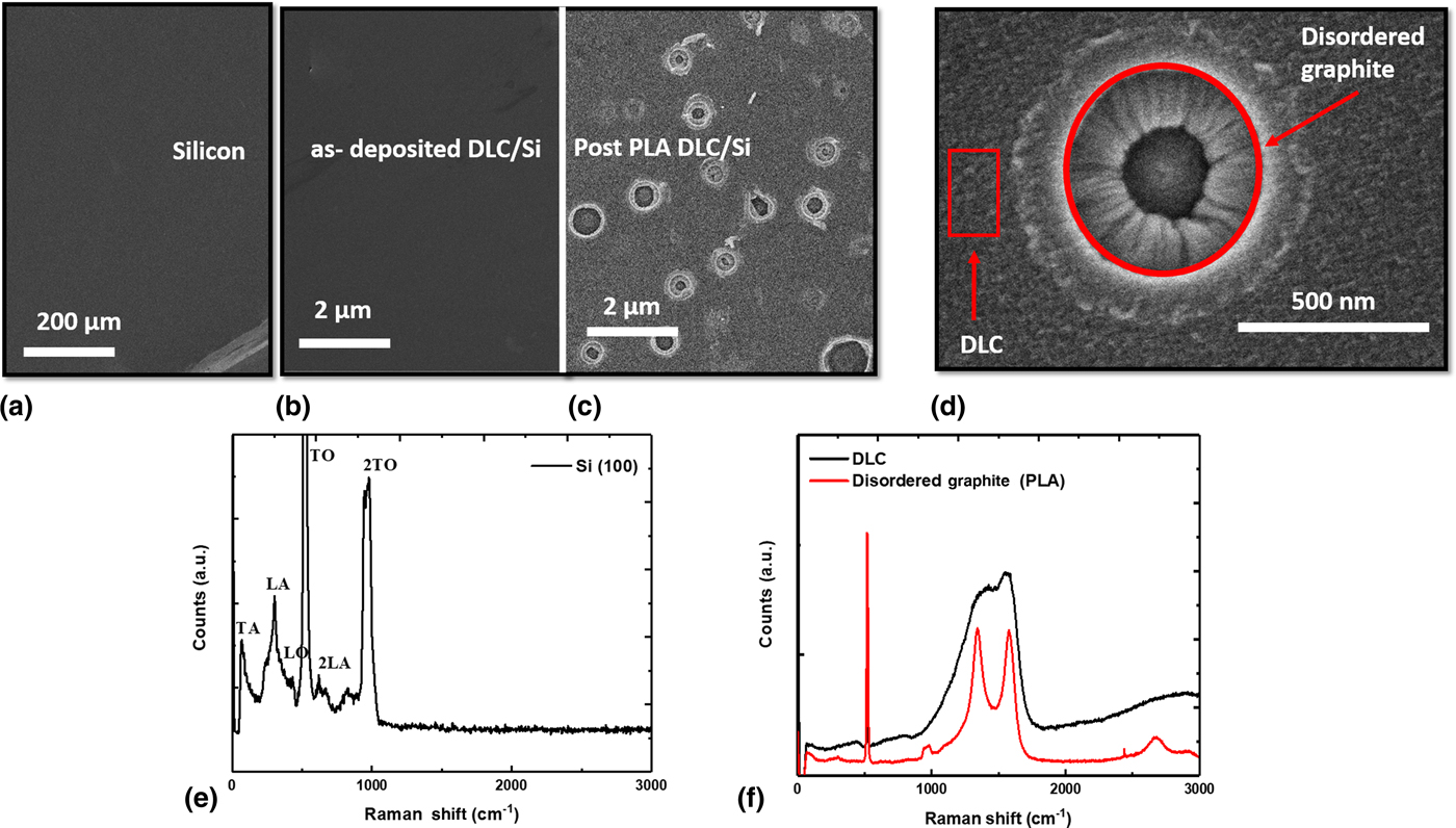
To determine the impact of undercooling, we deposited DLC on substrates with varied thermal conductivity, i.e., silicon and sapphire. Silicon is highly thermally conductive with 130 W/(m•K) thermal conductivity, whereas sapphire provides thermal insulation with a conductivity of 23.1 W/(m•K), at room temperature.[Reference Ho, Powell and Liley17] Figure 1(a and b) show the SEM micrograph of silicon and as-deposited DLC on silicon, highlighting the uniformity and conformal coverage of depositions. Upon PLA processing there is a significant change observed in the microstructure depicted in the micrographs of Fig. 1(c). As the underlying substrate for DLC growth in this case is silicon (high thermal conductivity), there is a low amount of heat trapped at the film interface. This leads to laser melting of a very thin layer of the film (simulated in Supplementary Fig. S1). Effectively, it becomes the case of a thin metallic melt layer positioned over an amorphous layer. The phenomenon observed here is fundamentally similar to laser dewetting, where a thin metal film breaks down into small droplets to minimize the surface energy upon performing PLA with a nanosecond laser.[Reference Sachan, Yadavali, Shirato, Krishna, Ramos, Duscher, Pennycook, Gangopadhyay, Garcia and Kalyanaraman18–Reference Sachan, Malasi, Ge, Yadavali, Krishna, Gangopadhyay, Garcia, Duscher and Kalyanaraman20] The radially increasing quenching rate led to the nanostructure as shown in high-resolution SEM image in Fig. 1(d). The ultrafast melting of the surface overlayer creates melt puddles on DLC. The critical radius of the melt puddle is proportional to h 5/3, where h is the melt depth.[Reference Trice, Thomas, Favazza, Sureshkumar and Kalyanaraman21] The melt depth is dependent on PLA energy density and depth of penetration of the nanosecond laser (λ ArF = 193 nm). The characteristic Raman spectra with all the vibrational modes for single crystalline (100) silicon are shown in Fig. 1(e). Figure 1(f) reveals the Raman spectra of as-deposited DLC and PLA processed thin films on silicon substrate, respectively. A convolution of Gaussian and Lorentzian profiles with peak positions are anchored at the characteristic peak positions for carbon-based materials −1140 cm−1 (T peak), 1332 cm-1 (D peak), and 1580 cm−1 (G peak) fits accurately to the acquired spectra.[Reference Bhaumik and Narayan22] For DLC thin films deposited on silicon, the sp 3 content is 70%. There are sharp D and G peaks noticeable in the Raman spectra acquired inside the melt puddle highlighting the presence of disordered graphite. It is interesting to note that the inside of the melt puddle is crystalline graphite, while the outer region exhibits similar DLC Raman spectra. When the melt quenches back at a slow rate, there is enough time for formation of energetically favorable crystalline polymorphs, i.e., diamonds and graphite. The observation of disordered graphite suggests slow regrowth rate of 1–2 m/s in the interior of melt puddle.
SEM image showing (a) silicon wafer; (b) as-deposited DLC; (c) PLA-processed disordered graphite; (d) high-resolution SEM image revealing the radial growth of disordered graphite from the melt puddle. Raman spectroscopy of (e) single crystalline (100)-oriented Si, highlighting all the vibrational modes; (f) as-deposited DLC and PLA processed disordered graphite.

Q-carbon formation on sapphire
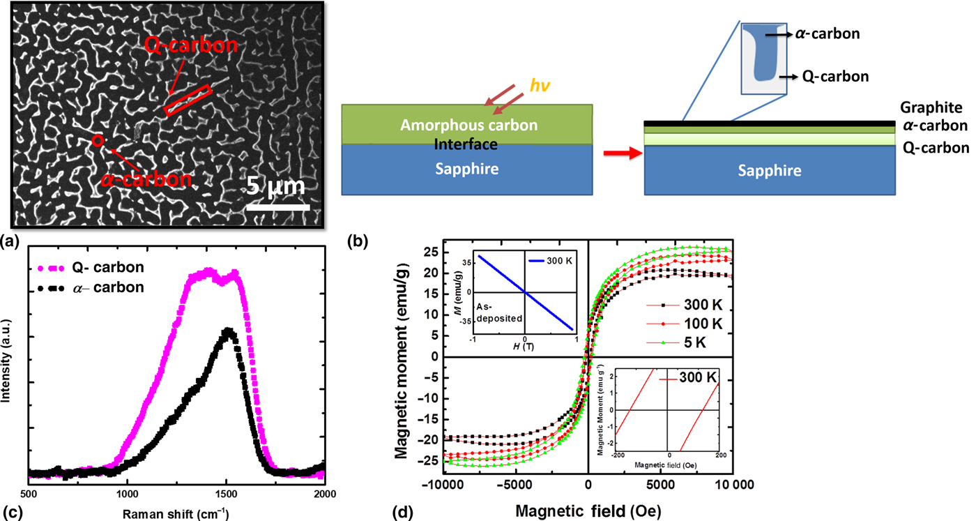
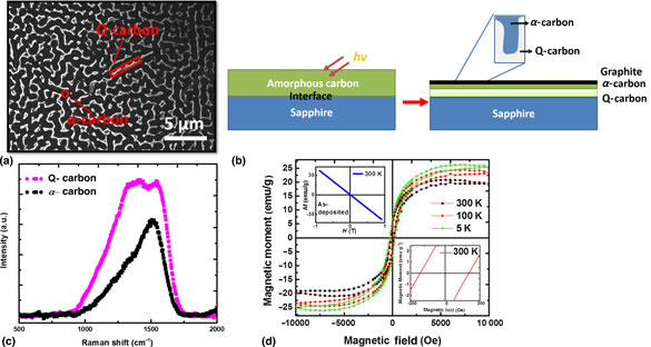
During solidification, a planar liquid–solid interface can become morphologically unstable above a certain solute concentration at a given velocity of solidification. This instability is termed “interfacial instability’. It induces the formation of “cellular” structures of a certain phase. In our case, we observe the formation of Q-carbon filamentary nanostructures inside the α-carbon matrix. The maximum sp 3 content in DLC, which resulted in successful laser melting and Q-carbon formation on sapphire, was determined to be ~80%.[Reference Gupta, Bhaumik, Sachan and Narayan3, Reference Gupta, Sachan, Bhaumik and Narayan9] As sp 3-rich DLC has higher thermal conductivity, upon PLA it results in the formation Q-carbon nanostructures throughout the laser annealed region. The sp 3 content in as-deposited DLC thin film on sapphire is 75%. The presence of sp 3–sp 3 bonded nanoclusters and sp 3 hybridized atomic orbitals in Q-carbon is revealed from the rise in T and D peak intensity, respectively, in the Raman spectrum for Q-carbon nanostructures. Figure 2(a) shows large-area coverage of Q-carbon cellular nanostructures on the sapphire substrate. The mechanism for formation of Q-carbon nanocomposites upon PLA of high sp 3 DLC films is illustrated in Fig. 2(b). Post-PLA, undercooling is highest at the substrate–melt interface, leading to the formation of distinct Q-carbon and α-carbon phases. Figure 2(c) shows the Raman spectra for the physically distinct Q-carbon and α-carbon phases. The Q-carbon phase has ~82% sp 3 content, while α-carbon has 40% sp 3 content. The conversion of homogenously coated 75% sp3 DLC thin film into physically distinct phases of Q-carbon and α-carbon, evidences laser melting and subsequent quenching. Notably, a sharp interface is observed between the Q-carbon and α-carbon phases, the ultrafast quenching and high undercooling. The porosity (~40 nm) and randomness associated these nanostructures highlights faster regrowth as compared to PLA of low and medium sp3 as-deposited thin films. The two phases of nanocomposites—sp 3-rich Q-carbon and sp 2-rich α-carbon have distinct mechanical properties. The Q-carbon is ~40% harder than diamond,[Reference Narayan and Bhaumik2, Reference Narayan, Gupta, Bhaumik, Sachan, Cellini and Reido8] while the α-carbon phase is devoid of sp 3 nanoclusters which makes it soft with a hardness of 18 GPa.[Reference Gupta, Sachan, Bhaumik and Narayan9] This nanostructuring is critical in providing the coating with lubrication reducing friction coefficient and wear rates in comparison to DLC coatings. This soft α-carbon phase is critical in providing the coating with lubrication, reducing friction coefficient and wear rates in comparison to DLC coatings. The nanocomposites are industrially relevant because they contain nanostructured superhard Q-carbon and soft lubricating α-carbon phases which form a conformal coating on the substrate due to the high thermal conductivity[Reference Shamsa, Liu, Balandin, Casiraghi, Milne and Ferrari15] (~3 W/(m•K)) of high sp 3 thin films. In comparison to Q-carbon (4–5 µm wide spaces) grown from moderate sp 3 DLC films, the nanocomposites have 7.5 times better submicron dispersion between the Q-carbon and α-carbon phases, which increases their toughness and durability.[Reference Gupta, Sachan, Bhaumik and Narayan9]
(a) SEM image showing the conformal coverage of Q-carbon embedded in α-carbon matrix; (b) mechanism illustrating the formation of Q-carbon nanostructures upon PLA of DLC thin films; (c) Raman spectra of PLA-processed Q-carbon and α-carbon nanostructures; (d) Isothermal M–H plots for Q-carbon nanocomposites at various temperatures (300, 100, and 5 K) with inset (bottom-right) illustrating the finite coercivity of 140 Oe at 300 K. The inset in top-left reveals the diamagnetic nature of as-deposited DLC at 300 K.
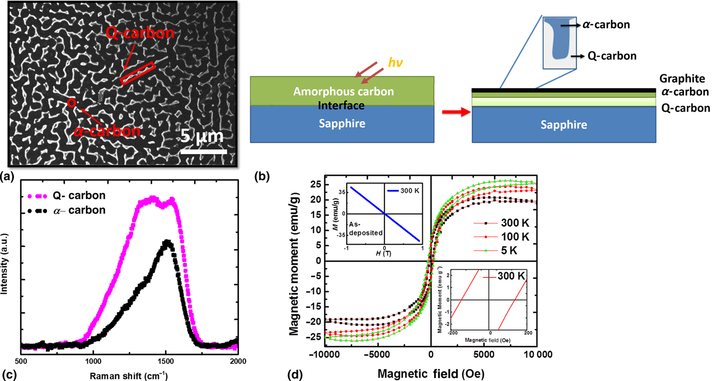
The magnetic properties of Q-carbon nanocomposites are analyzed in isothermal conditions via SQUID magnetometry by generating magnetization hysteresis (M versus H) loops. The calibration of SQUID before performing measurements was done with standard cobalt control sample. The nanocomposites exhibit room-temperature ferromagnetism as shown in Fig. 2(d) with a finite coercivity of 140 Oe as revealed in the inset. The saturation magnetization for Q-carbon nanocomposites at 5 K is determined to be 22.40 emu/g. Ferromagnetism arises in carbon derivatives due to the positive value of exchange energy and magnetic coupling between unpaired electrons in π-orbitals. The increased rate of heat loss in direction of the melt front, due to the usage of thermally insulating sapphire substrate, coupled with higher thermal conductivity of high sp3 DLC generates an unprecedented number of pπ dangling bonds in Q-carbon. These bonds contain unpaired spins generating ferromagnetism inside the Q-carbon matrix. The increase in exchange energy occurs due to electronic interactions between sp 2 and sp 3 hybridized carbon atomic orbitals. In Q-carbon, there is a high density of electronic states near the Fermi level,[Reference Bhaumik, Nori, Sachan, Gupta, Kumar, Majumdar and Narayan10] indicating a significant number of dangling bonds. Due to the smaller cellular size of Q-carbon in nanocomposites, the average magnetic domain size decreases, thereby generating more phase boundaries. These phase boundaries act as pinning centers, increasing the activation energy required for flipping the magnetic domain spin states upon introduction of the magnetic field. The increase in activation energy is apparent from the rise in coercivity from 80 Oe in Q-carbon[Reference Narayan and Bhaumik2] to 140 Oe in Q-carbon nanocomposites at 300 K. Notably, DLC also has disordered sp 2–sp 2 bonds truncated with sp 2–sp 3 bonding. Such disorder should generate unpaired electrons, inducing ferromagnetic ordering. However, we observe diamagnetism in DLC [inset in top-left Fig. 2(d)], highlighting the fact that it is a physical mixture of sp 2 and sp 3 bonded clusters.
Diamond growth
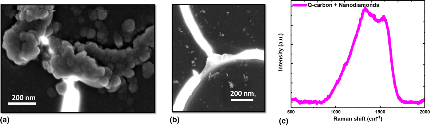
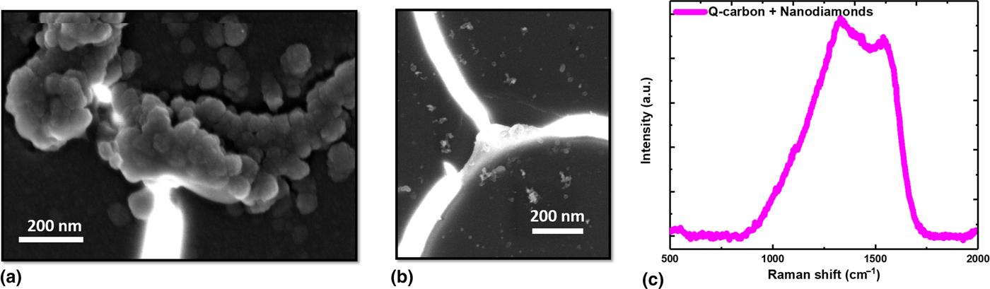
PLA of Q-carbon induces remelting and nanodiamonds nucleate at the Q-carbon nanostructures as depicted in Fig. 3(a). The nanodiamonds preferentially nucleate at the triple points, where the filamentary structures of Q-carbon intersect as shown in Fig. 3(b).[Reference Narayan and Bhaumik2] The average size of nanodiamonds is ascertained to be ~60 nm. As the PLA process ends in less than 200 ns, the growth rate of diamonds is ~3 m/s.[Reference Narayan and Bhaumik2] The conventional equilibrium-based methods like CVD take 3–4 h, to deposit microdiamonds leading to a growth rate ~10−9 m/s. At low regrowth velocity, carbon atoms have sufficient time to rearrange, forming relatively thermodynamically stable crystalline nanodiamonds. The width of filamentary nanostructures of Q-carbon is measured to be 300 nm with nanodiamonds embedded in it. Upon further PLA, Q-carbon filament breaks apart, providing nucleation sites for diamond growth.[Reference Gupta, Bhaumik, Sachan and Narayan3, Reference Bhaumik and Narayan23] Even in the absence of a crystalline template, the formation of nanodiamond occurs due to the homogeneous nucleation driven by high undercooling in the melt state. The Raman spectrum acquired around these intersecting triple points of Q-carbon have a peak shoulder ~1331 cm−1, as highlighted in Fig. 3(c). Diamond is a monoatomic system having first-order phonon with the symmetry T 2g at 1332 cm−1 which is the only Raman active mode. This mode in diamond corresponds to the vibrations associated with two interpenetrating cubic sublattices. The minimal blue-shift observed in the T 2g peak occurs due to size effects in nanodiamonds.
High-resolution SEM image showing the (a) remelted Q-carbon filamentary nanostructure with nanodiamonds nucleating on it; (b) nanodiamond nucleating at the intersecting triple point of Q-carbon; (c) Raman spectroscopy remelted Q-carbon nanostructure and nanodiamonds.
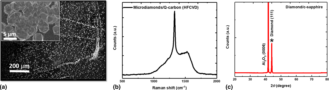
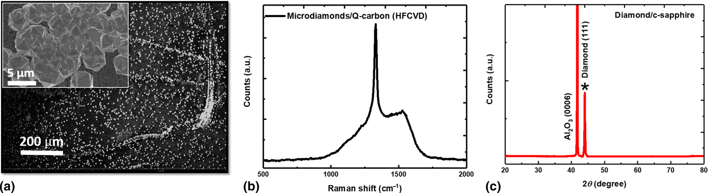
Microdiamonds (~5 µm) are grown using Q-carbon as the seed layer using HFCVD as shown in Fig. 4(a). During the HFCVD growth, the Q-carbon provides nucleation sites for microdiamond growth. These nucleation sites facilitate the crystal growth in less time than the conventional CVD process.[Reference Narayan and Bhaumik2] In the conventional CVD technique where diamond surface graphitization occurs due to the slow growth rate, it leads to “cauliflower” diamond growth due to the re-nucleation of nanodiamonds on the graphitc overlayer. For HFCVD growth on Q-carbon, due to faster growth, the formation of “hexagonal” twinned microdiamonds occurs as depicted in the inset of Fig. 4(a).[Reference Narayan24] The Raman spectrum for the microdiamonds exhibits the strong T 2g diamond peak arising from the interpenetrating FCC sublattices at 1332 cm−1 as revealed in Fig. 4(b). A small broad G peak at ~1550 cm−1, reveals low amount of graphitization at the microdiamond surface. A small peak ~1150 cm−1 is also observed, which originates from the sp 3 nanoclusters. Figure 4c shows XRD pattern of the diamond film growth on sapphire revealing a sharp and well-defined peak (*) at 2θ = 43.9° highlighting the strongly textured growth of (111)-oriented microdiamonds.
(a) HFCVD growth of microdiamonds over PLA processed Q-carbon. The inset highlights the large area growth of microdiamonds (b) Raman spectrum for microdiamonds grown over Q-carbon with signature 1331 cm−1 diamond peak; (c) XRD pattern of the diamond film, highlighting the diamond (111) peak at 43.9° (*), grown on c-sapphire for growth from seeded Q-carbon nanostructures via HFCVD.
Crystal growth from the amorphous DLC films upon PLA is a first order phase transformation. The transformation is driven by the motion of melt interface between the two coexisting phases. As PLA process for DLC thin films ends in less than 200 ns, the solid regrowth rates achieved are orders of magnitude higher in comparison with conventional crystal growth processes.[Reference Narayan and Bhaumik2, Reference Bhaumik and Narayan23] The nature of growth changes from crystalline to amorphous, depending on incorporation rate of carbon atoms during solidification. In case of Si and GaAs, rise in regrowth velocity induces an increase in disorder, creating defects and twinning, and a further rise in regrowth rates induces amorphization.[Reference Kumomi14]
For PLA of sp 3-rich DLC films above a specific sp 3 content, the formation of nanodiamonds is not energetically favorable, resulting in amorphization of the melt. Amorphization occurs when the undercooling is high enough to make amorphization rate kinetically faster than the competing crystal growth. Post-melting, the melt regrowth velocity is a function of undercooling, due to viscosity effects.[Reference Jackson, Poate, Foti and Jacobson25] For PLA, regrowth velocity (V) during interfacial regrowth at the temperature (T) is given by:
 $$V \; \sim \displaystyle{{D_\alpha {\rm f}} \over {{\rm \lambda} f_D}}\left( {1 - e^{\left( {{{ - \Delta G_T} / {}}kT} \right)}} \right)\; \; $$
Here, D α is diffusivity in melt state ~10−8 m2/s, f D is the geometric factor related to diffusion, f is the fraction of atomic sites available for the atomic jump, and λ is the atomic jump distance across the melt interface (1.31 Å for carbon).[Reference Narayan26, Reference Spaepen, Turnbull, Poate, Mayer, Poate and Mayor27] As amorphization and crystallization compete kinetically during regrowth:
 $$\Delta G_m = \Delta H - {\rm} T_m\Delta S_m.$$
 $$\Delta G_u = \Delta H{\rm} - {\rm} T_u\Delta S_u.$$
Here, subscripts m and u denote the melt state and undercooled state, respectively.
 $$\Delta G_T = (\Delta G_m - {\rm} \Delta G_u) = T_u\Delta S_u - {\rm} T_m\Delta S_m.$$
Here ΔT u = T u − T m is the observed undercooling.
When the following condition is satisfied, energetically there is a possibility of amorphous regrowth:
 $$\Delta T_{u} \ge \Delta T_{c} = T_m^{{\rm diamond}} - T_m^{{\rm amorphous}}. $$
In case of carbon, the critical undercooling for amorphization (ΔT c ) ~1000 K.[Reference Spaepen, Turnbull, Poate, Mayer, Poate and Mayor27] Once observed undercooling (ΔT u )>ΔT c, the growth of Q-carbon occurs. At low regrowth velocity (1-2 m/s), low undercooling induces graphitization, as revealed experimentally in Fig. 1. The increase in regrowth velocity induces a rise in undercooling, inducing nucleation of nanodiamonds. For crystal growth, low atom impinging rate is required for generation of order. Above a critical regrowth velocity, the carbon atoms impinge at a very fast rate, making amorphous regrowth energetically favorable as compared to nanodiamond nucleation. Above this critical velocity, growth of amorphous Q-carbon devoid of diamonds should be observed. On solving Eq. (1) with ΔG amorphous instead of ΔG diamond, the critical velocity for amorphization was determined to be 16 m/s. At intermediate regrowth velocity, it is possible to form nanodiamonds and Q-carbon simultaneously. In silicon, which has the same diamond-cubic lattice, twinning occurs in the intermediate nanocrystal–amorphization range. Hence, presence of twins and stacking faults is expected in microdiamonds grown by explosive crystallization upon remelting of Q-carbon seeds.[Reference Cullis, Chew, Webber and Smith28]
As the thermal conductivity (k) of liquid carbon is constant (2.9 W/(cm•K)), the heat loss in direction of the melt front is given by (ΔQ/Δt) is given by:
 $${\Delta Q} {\left / {\vphantom {{\Delta Q} {\Delta t}}}\right.} {{\Delta t}} = {\rm kA} \; \left( {T_0 - T_m} \right)/{\rm L}{\rm .} $$
Here T 0 is the ambient temperature. An insulating substrate like sapphire traps more heat at the substrate–melt interface, triggering a rise in temperature of melt (T m), increasing heat loss in direction of the melt front. As the melt solidifies and undergoes regrowth, the extent of undercooling plays a decisive role in determining the carbon polymorph regrown. Classically, once melting occurs and melt front is established, undercooling (ΔT u) and regrowth rate (V) are interdependent as given by:
 $$\Delta T_u = \displaystyle{{{\rm R}T_m^2} \over {\Delta H_f}}\displaystyle{{\rm V} \over {V_0}}.$$
For DLC grown on sapphire, the increased heat loss in the direction of the melt front causes faster solidification i.e., high regrowth velocity (>16 m/s), resulting in high undercooling (ΔT u)(~1000 K).[Reference Narayan and Bhaumik2] Such a high undercooling triggers formation of metastable nanodiamonds or Q-carbon at the substrate–melt interface. For DLC grown on silicon, due to the leakage of heat flux from the substrate, the heat loss in direction of the melt front is low. It results in low regrowth velocity (1–2 m/s) from the melt state. At such regrowth velocities, the undercooling achieved is low and it induces growth of thermodynamically stable phase of graphite. In case of temporally longer laser pulses, the melt lifetime is long enough to nucleate nanocrystallites at the substrate/melt interface. The solid regrowth releases latent heat of fusion, which further extends the melt front. Melting terminates when the released heat is insufficient to melt the solid layer beneath the melt interface. For shorter pulses, nanodiamond nucleation is suppressed due to higher regrowth velocity.
To study the mechanism of melt regrowth during laser annealing, finite-element simulations using heat flow equations are performed for DLC/Si and DLC/sapphire systems.[Reference Singh and Narayan29] Figure S1(a) of the supporting information depicts the temperature profiles at the thin film surface. The phase transformation of solid DLC to carbon melt and back to regrown solid, are reflected by the cusps on the temperature–time SLIM profiles at 5 and 100 ns, respectively, for PLA processing of DLC on sapphire. It also provides estimates for instability at the melt front as huge thermal gradients get established during melting as revealed in Fig. S1(b). During PLA of DLC grown over Si, the high thermal conductivity of Si makes it an effective heat sink, reducing the temperature at substrate/film interface. It is reflected in the surface temperature profiles in Fig. S1(a) and in the temperature distribution with depth in Fig. S1(c). As the melt front is unable to reach the substrate, the effective undercooling achieved in case of silicon is very low, resulting in growth of thermodynamically stable graphite, as shown in Fig. 1. Evidently, these simulations reveal that significant undercooling is achieved at the melt/substrate interface upon decreasing substrate thermal conductivity. Hence, the substrate can be tailored to actuate the growth of crystalline graphite, diamond, or amorphous Q-carbon phases upon laser annealing.
Conclusions
In this article we have provided estimates for regrowth velocity and extent of undercooling by employing experimental and theoretical considerations for the phase transformation of DLC into crystalline graphite, nanodiamonds, and Q-carbon. DLC thin films were deposited with similar sp3 content on substrates having different thermal conductivity, i.e., silicon and sapphire. The morphological changes during PLA of DLC films were studied and correlated with the expected undercooling. It was found that substrate heat capacity and thermal conductivity are related to the undercooling and regrowth velocity during melt regrowth. The higher thermal conductivity of substrates like silicon facilitates the growth of crystalline graphite and diamond, however Q-carbon formation requires thermally insulating substrates like sapphire. By controlling the regrowth velocity, we can optimize undercooling to nucleate a fixed number of nanodiamonds around the amorphous matrix. Upon doping with N, such standardization provides exciting implications towards quantum computing via entanglement of N–V centers. Increased undercooling triggered by high regrowth velocities will lead to higher solute trapping of dopants in PLA processed doped Q-carbon films, resulting in nanostructures with novel properties like high-temperature superconductivity and enhanced hardness. Also, it is highlighted that increased undercooling leads to the conformal growth of Q-carbon filamentary nanostructures inside the soft α-carbon matrix which is an ideal composite for coating and drilling applications due to the increased toughness originating from its nanostructuring. It will be interesting to explore the dopant redistribution and change in the physical properties of doped nanodiamonds and Q-carbon films upon HFCVD growth into microdiamonds and doped-diamond films.
SUPPLEMENTARY MATERIAL
The supplementary material for this article can be found at https://doi.org/10.1557/mrc.2018.76
Acknowledgments
We are thankful to the Fan Family Foundation Distinguished Chair Endowment for J. Narayan. R. Sachan acknowledges National Academy of Sciences (NAS), USA for awarding the NRC research fellowship. This work was performed under the National Science Foundation Award number DMR-1735695. We used Analytical Instrumentation Facility (AIF) at North Carolina State University for performing the structural characterization of thin films.
Competing Financial Interests statement
The authors declare no competing financial interests.