1 Introduction
The stability and breakdown of vortex flows arise in various engineering applications ranging from high-performance flight vehicles to power generation gas turbines and aircraft turbo-jet engines. Of specific interest is the dynamics of vortices above thin, slender, sweptback wings operating at high angles of attack, vortices at the tip of aircraft wings, vortices behind rotating blades of helicopters, wind and gas turbines and swirling flows in combustion chambers or in nozzles. The vortex-breakdown phenomenon is characterized by a sudden and abrupt change in the flow structure from an upstream strong vortex jet to a downstream weak and wide swirling wake when the upstream swirl ratio is above a certain critical level. A free stagnation point appears along the vortex centreline followed by a large scale flow separation region and an increased level of turbulence behind it. This topic was reviewed in the papers by Hall (Reference Hall1972), Leibovich (Reference Leibovich1984), Escudier (Reference Escudier1988), Delery (Reference Delery1994), Althaus, Bruecker & Weimer (Reference Althaus, Bruecker, Weimer and Green1995), Sarpkaya (Reference Sarpkaya1995) and Mitchell & Delery (Reference Mitchell and Delery2001). Moreover, in a recent experimental study, Dennis, Seraudie & Poole (Reference Dennis, Seraudie and Poole2014) found the existence of another vortex-breakdown phenomenon in which the swirling flow evolves to a wall-separation state. This state is characterized by an abrupt change of the upstream rotating flow near the wall to a downstream large near-stagnation zone attached to the wall when the upstream swirl ratio is above another certain critical level. Depending on the operational apparatus conditions, the flow may settle on the breakdown or wall-separation states at the same swirl levels.
In an attempt to better understand the fundamentals of the vortex-breakdown phenomena, the dynamics of isolated vortex flows in tubes was studied. Vortex breakdown in pipe flows has been observed to exhibit several major structures. Sarpkaya (Reference Sarpkaya1971, Reference Sarpkaya1974) and Faler & Leibovich (Reference Faler and Leibovich1977) experimentally documented the appearance of the axisymmetric bubble with a helical tail, as well as the spiral and the double-helix breakdown states at relatively low Reynolds numbers (
 $Re$
; based on pipe diameter and the characteristic axial speed at the pipe inlet) of the order of
 $500$
–
 $10\,000$
(also see Liang & Maxworthy Reference Liang and Maxworthy2005). It was found that the various types of disrupted vortex states may coexist at relatively low Reynolds numbers (
 $Re<2000$
). However, the axisymmetric bubble-type breakdown was encountered more frequently as
 $Re$
or the inlet swirl level were increased (Leibovich Reference Leibovich1984).
Sarpkaya (Reference Sarpkaya1995) and Novak & Sarpkaya (Reference Novak and Sarpkaya2000) extended the experimental studies to swirling flows with much higher
 $Re$
, of the order of
 $50\,000$
–
 $300\,000$
. They found that the bubble breakdown was replaced by an open downstream breakdown zone; the vortex core initiated a kink at a certain point which was followed by a short rotating spiral wave and a sudden burst into three-dimensional turbulence, while the outer core flow expanding around an open centreline zone was nominally an axisymmetric swirling wake flow. As
 $Re$
was increased above
 $100\,000$
the structure of the open breakdown zone appeared to be a basic shape of vortex breakdown at very high
 $Re$
. The open axisymmetric breakdown zone was also found in vortex flows over slender wings at high angles of attack (Delery Reference Delery1994; Mitchell & Delery Reference Mitchell and Delery2001) and in swirling flows in open combustion chambers (Umeh et al.
Reference Umeh, Rusak, Gutmark, Villalva and Cha2010).
Most of the experimental vortex tube investigations used pipes with a contraction followed by a long diverging pipe configuration (Sarpkaya Reference Sarpkaya1971, Reference Sarpkaya1974, Reference Sarpkaya1995; Faler & Leibovich Reference Faler and Leibovich1977; Garg & Leibovich Reference Garg and Leibovich1979). In addition, the leading edge vortices over slender wings are subjected to diverging streamtubes around them with an axial adverse pressure gradient (Delery Reference Delery1994; Mitchell & Delery Reference Mitchell and Delery2001). All industrial combustion chambers use a significant divergence of the geometry to form large axisymmetric vortex-breakdown zones and to stabilize flames (Umeh et al. Reference Umeh, Rusak, Gutmark, Villalva and Cha2010). On the other hand, nozzles of afterburners use geometry contraction to accelerate the flow. Also, the intake flow into a turbo-jet or turbofan engine forms a streamwise contracting streamtube ahead of the inlet; when a streamwise vortex is captured in the centre of this streamtube, it intensifies its swirl ratio and may degrade the operation of the compressor or fan of the engine (Mclelland, MacManus & Sheaf Reference Mclelland, MacManus and Sheaf2015). The effect of geometry changes on vortex flow dynamics plays a role in the transition to breakdown but cannot be systematically isolated in experiments to be used properly in applications.
A number of theories were suggested to explain the vortex-breakdown phenomena including: (i) the classical vortex stability theory of Kelvin (Reference Kelvin1880), Rayleigh (Reference Rayleigh1916), Synge (Reference Synge1933), Howard & Gupta (Reference Howard and Gupta1962), Lessen, Singh & Paillet (Reference Lessen, Singh and Paillet1974) and Leibovich & Stewartson (Reference Leibovich and Stewartson1983) (also see the review of Ash & Khorrami Reference Ash, Khorrami and Green1995); (ii) the critical-state approach of Squire (Reference Squire1960) and Benjamin (Reference Benjamin1962, Reference Benjamin1967); (iii) the bifurcation of trapped solitary-wave states from Benjamin’s critical state by Randall & Leibovich (Reference Randall and Leibovich1973) and Leibovich & Kribus (Reference Leibovich and Kribus1990); (iv) the analogy to boundary layer separation by Hall (Reference Hall1972); (v) the stagnation zone states in inviscid swirling flows by Escudier & Keller (Reference Escudier and Keller1983) and Keller, Egli & Exley (Reference Keller, Egli and Exley1985); (vi) the development of azimuthal vorticity along a pipe centreline by Brown & Lopez (Reference Brown and Lopez1990); (vii) the theory of the dynamics of inviscid swirling flows in a diverging pipe by Buntine & Saffman (Reference Buntine and Saffman1995); (viii) the formation of axisymmetric finite-amplitude waves and separation zones on viscous, near-critical, swirling flows by Bossel (Reference Bossel1969), Lavan, Nielsen & Fejer (Reference Lavan, Nielsen and Fejer1969), Grimshaw & Yi (Reference Grimshaw and Yi1993) and Hanazaki (Reference Hanazaki1996); and (ix) the structure of a swirling flow around a stagnation point by Rusak (Reference Rusak1996). These theoretical approaches highlighted only certain aspects of the vortex-breakdown phenomenon and developed concepts toward its understanding. However, none of them provided a global approach for this phenomenon.
It is the global bifurcation and stability theory of Wang & Rusak (Reference Wang and Rusak1996, Reference Wang and Rusak1997a ,Reference Wang and Rusak b ), followed by the recent studies of Rusak et al. (Reference Rusak, Wang, Xu and Taylor2012) and Rusak & Wang (Reference Rusak and Wang2014), that formed a fundamental theory which links between vortex flow criticality, vortex stability to small-amplitude perturbations and the vortex-breakdown process. This theory provides details of vortex flow dynamics and links between the studies of Benjamin (Reference Benjamin1962), Hall (Reference Hall1972), Keller et al. (Reference Keller, Egli and Exley1985), Brown & Lopez (Reference Brown and Lopez1990), Leibovich & Kribus (Reference Leibovich and Kribus1990) and Buntine & Saffman (Reference Buntine and Saffman1995).
Wang & Rusak (Reference Wang and Rusak1996, Reference Wang and Rusak1997a
) studied the vortex-breakdown process of an inviscid-limit, incompressible, axisymmetric swirling flow in a finite-length, straight circular pipe, to represent the dynamics of high-
 $Re$
vortex flows. Their physical model considered a vortex generator ahead of the pipe, at a steady, smooth and continuous operation. It was assumed that the vortex generation process does not interact with the flow evolution in the pipe. The generated profiles of the axial and circumferential velocities and of the azimuthal vorticity entering the pipe were prescribed to be steady at some cross-section downstream of the vortex generator, which was denoted as the pipe inlet. In order to account for the effect of disturbances in the pipe that propagate upstream, the flow at the inlet was free to develop a radial velocity as a function of the swirl level and the evolving disturbance size. The pipe was assumed to be sufficiently long such that the outlet flow was considered as a parallel flow state with zero radial velocity and zero axial gradients of the circulation and azimuthal vorticity (a passive discharge device). The flow in the pipe was constrained by an inviscid no-penetration wall condition. This physical model was used to develop a mathematical problem based on the unsteady axisymmetric, incompressible and inviscid flow equations with the assumed boundary conditions. The analysis focused on the Squire–Long equation (SLE) of steady flow states (Long Reference Long1953; Squire Reference Squire, Batchelor and Davies1956). A variational energy functional
 ${\mathcal{E}}$
that corresponds to the SLE was used to determine branches of steady states as a function of the incoming flow swirl ratio,
 $\unicode[STIX]{x1D714}$
, including linearly stable global and local minimum states of
 ${\mathcal{E}}$
and unstable min–max states of
 ${\mathcal{E}}$
.
Wang & Rusak (Reference Wang and Rusak1997a
) revealed the existence of three branches of steady equilibrium vortex states, connected by two critical levels of the incoming flow swirl ratio,
 $\unicode[STIX]{x1D714}_{0}$
and
 $\unicode[STIX]{x1D714}_{1}$
, where
 $\unicode[STIX]{x1D714}_{0}<\unicode[STIX]{x1D714}_{1}$
(see figure 15 in Wang & Rusak Reference Wang and Rusak1997a
). The critical swirl
 $\unicode[STIX]{x1D714}_{1}$
is an extension for a finite-length pipe of Benjamin (Reference Benjamin1962) critical swirl and
 $\unicode[STIX]{x1D714}_{0}$
is an extension for a finite-length pipe of Keller et al. (Reference Keller, Egli and Exley1985) special swirl level. The base branch of columnar (parallel) flow vortex states is composed of asymptotically stable, global minimum states of
 ${\mathcal{E}}$
when
 $0\leqslant \unicode[STIX]{x1D714}<\unicode[STIX]{x1D714}_{0}$
, linearly stable local minimum states of
 ${\mathcal{E}}$
when
 $\unicode[STIX]{x1D714}_{0}<\unicode[STIX]{x1D714}<\unicode[STIX]{x1D714}_{1}$
and unstable min–max states of
 ${\mathcal{E}}$
when
 $\unicode[STIX]{x1D714}>\unicode[STIX]{x1D714}_{1}$
. A branch of unstable, min–max, solitary-wave states of
 ${\mathcal{E}}$
connects the columnar state at
 $\unicode[STIX]{x1D714}_{1}$
to a breakdown state at
 $\unicode[STIX]{x1D714}_{0}$
. These are similar to the states found by the Leibovich & Kribus (Reference Leibovich and Kribus1990) analysis. A branch of breakdown states starts from the critical swirl ratio
 $\unicode[STIX]{x1D714}_{0}$
and describes global minimum states of
 ${\mathcal{E}}$
for
 $\unicode[STIX]{x1D714}>\unicode[STIX]{x1D714}_{0}$
. These states describe a core swirling flow expanding axisymmetrically around an open, centreline stagnation zone, similar to the breakdown states found by Sarpkaya (Reference Sarpkaya1995) and Novak & Sarpkaya (Reference Novak and Sarpkaya2000) at very high
 $Re$
. Mattner, Joubert & Chong (Reference Mattner, Joubert and Chong2002) found agreement between their experimental results and the theoretical predictions of Rusak, Whiting & Wang (Reference Rusak, Whiting and Wang1998).
The theory of Wang & Rusak (Reference Wang and Rusak1996, Reference Wang and Rusak1997a
) shows that the vortex-breakdown process in high
 $Re$
flows is a necessary evolution from an initially perturbed vortex flow to another lower-energy equilibrium state describing a vortex-breakdown state when
 $\unicode[STIX]{x1D714}>\unicode[STIX]{x1D714}_{0}$
(also see Rusak et al.
Reference Rusak, Wang, Xu and Taylor2012). This evolution is driven by the interaction between azimuthal vorticity perturbations propagating upstream and the relatively fixed incoming vortex flow. This interaction is a direct result of flow axial inhomogeneity induced by the no periodicity relationship between the fixed inlet conditions and the passive outlet conditions (Wang & Rusak Reference Wang and Rusak2011, also see Gallaire & Chomaz Reference Gallaire and Chomaz2004). It leads to a decreasing margin of stability of the columnar flow as
 $\unicode[STIX]{x1D714}$
approaches
 $\unicode[STIX]{x1D714}_{1}$
and a global loss of stability of the base columnar states when
 $\unicode[STIX]{x1D714}$
is above
 $\unicode[STIX]{x1D714}_{1}$
. On the other hand,
 $\unicode[STIX]{x1D714}_{0}$
is the first swirl level above which finite-size, stable breakdown states can exist. Large finite-size axisymmetric disturbances decay to the columnar state when
 $\unicode[STIX]{x1D714}<\unicode[STIX]{x1D714}_{0}$
. Thus,
 $\unicode[STIX]{x1D714}_{0}$
is a threshold level of the incoming flow swirl ratio, and
 $\unicode[STIX]{x1D714}>\unicode[STIX]{x1D714}_{0}$
is a necessary condition for breakdown states to exist, while
 $\unicode[STIX]{x1D714}>\unicode[STIX]{x1D714}_{1}$
is a sufficient condition for breakdown states to appear in a straight pipe.
The direct numerical simulations of Ruith et al. (Reference Ruith, Chen, Meiburg and Maxworthy2003) and the linear and weakly nonlinear stability analyses of Gallaire & Chomaz (Reference Gallaire and Chomaz2003), Gallaire et al. (Reference Gallaire, Ruith, Meiburg, Chomaz and Huerre2006), Meliga, Gallaire & Chomaz (Reference Meliga, Gallaire and Chomaz2012), Qadri, Mistry & Juniper (Reference Qadri, Mistry and Juniper2013) and Wang et al. (Reference Wang, Rusak, Gong and Liu2016) extended the stability and bifurcation results of Wang & Rusak (Reference Wang and Rusak1996, Reference Wang and Rusak1997a ) and determined unstable spiral and double-helical perturbations in vortex flows in a finite-length pipe. Gallaire et al. (Reference Gallaire, Ruith, Meiburg, Chomaz and Huerre2006) explained the spiral breakdown in terms of an absolute instability of the axisymmetric breakdown state. The Wang et al. (Reference Wang, Rusak, Gong and Liu2016) analysis, based on the Reynolds–Orr equation, showed that axial flow inhomogeneity by the inlet–outlet conditions can also form unstable three-dimensional modes.
The effect of pipe geometry expansion or contraction was studied in Rusak & Judd (Reference Rusak and Judd2001) and Rusak & Meder (Reference Rusak and Meder2004). Through an asymptotic analysis of the dynamics of axisymmetric swirling flows at near-critical swirl levels around
 $\unicode[STIX]{x1D714}_{1}$
, it was found that slight pipe divergence induces the appearance of breakdown at lower incoming flow swirl ratios and reduces
 $\unicode[STIX]{x1D714}_{1}$
while slight contraction delays breakdown appearance to higher swirl ratios and increases
 $\unicode[STIX]{x1D714}_{1}$
. The pipe geometry adds to the flow axial inhomogeneity caused by the inlet and outlet conditions and can even dominate it. However, these studies were not extended to investigating the effect of pipe divergence or contraction on swirling flows global dynamics, specifically the calculation of the threshold swirl level for the appearance of breakdown or wall-separation states as a function of geometry changes.
In parallel, extensive computational studies to determine steady-state solutions of the inviscid flow equations for swirling flows in diverging and contracting pipes were conducted by Buntine & Saffman (Reference Buntine and Saffman1995) and Leclaire, Sipp & Jacquin (Reference Leclaire, Sipp and Jacquin2007), respectively. Both studies faced the same difficulty of continuing the branches of steady-state solutions when a stagnation point appeared at the pipe outlet and where non-regular solutions that may describe a separation zone along the pipe centreline or attached to the pipe wall must develop. Both stopped the computations at such states. Following the ideas developed in Rusak & Wang (Reference Rusak and Wang2014), the present work tackles this issue by formulating additional conditions on the solutions that allow the appearance of stagnation zones along the centreline or the pipe wall.
The numerical flow simulations of Rusak et al. (Reference Rusak, Wang, Xu and Taylor2012) and Rusak & Wang (Reference Rusak and Wang2014) have demonstrated the appearance of stagnation zones in swirling flows in a straight circular pipe as a result of flow evolution and the establishment of time-asymptotic states. Specifically, it has been shown that when the incoming flow swirl ratio is above the critical level
 $\unicode[STIX]{x1D714}_{0}$
, an infinitesimal flow flux around the centreline evolves naturally into a state with a large-size stagnation (breakdown) zone around the centreline. The vortex-breakdown states are found in the present study to play a dominant role in flow dynamics when pipe divergence is considered.
In addition, the study of Rusak & Wang (Reference Rusak and Wang2014) has established the existence of wall-separation states in swirling flows in a straight pipe, in tandem with vortex-breakdown states. The appearance of wall-separation zones was first inferred in the study of Rusak & Meder (Reference Rusak and Meder2004) and later by Leclaire et al. (Reference Leclaire, Sipp and Jacquin2007) and Leclaire & Sipp (Reference Leclaire and Sipp2010). These states are characterized by a quasi-stagnation zone that is attached to the pipe wall. Within this zone, the axial and radial velocities vanish, but the circumferential velocity and pressure vary within the zone. These wall zones grow in size with the increase of incoming swirl ratio above the critical level. The wall-separation states are stable and have their own domain of attraction in terms of initial conditions and evolution of perturbations. These zones are formed out of an infinitesimal inlet flow flux with swirl that is attached to the wall and grows into a finite-size quasi-stagnation zone. The wall-separation states are found to have a dominant role in flow dynamics when pipe contraction is considered. Such states have been recently documented in the experiments of Dennis et al. (Reference Dennis, Seraudie and Poole2014).
The goal of this paper is to develop a global analysis theory of the dynamics of inviscid-limit axisymmetric swirling flows in finite-length, diverging or contracting, long pipes to represent the nature of high
 $Re$
vortex flows (
 $Re>100\,000$
). Such flows cannot yet be simulated by direct numerical simulations. We assume that the axial and circumferential wall boundary layers stay sufficiently thin and do not affect the flow in the bulk, even when vortex breakdown or wall-separation zones appear. We show that solutions of the columnar (axially independent) SLE problem can predict the nature of major flow states in the pipe and the effect of pipe geometry. Numerical solutions of the SLE problem and numerical unsteady flow simulations are used to realize the various states. We find that pipe divergence promotes the appearance of vortex-breakdown states at lower swirl ratios while pipe contraction promotes wall-separation states. These new results can guide future viscous swirling flow simulations in realistic apparatus configurations. They can also be used in the design of combustion chambers and diffusers of jet-and hydro-electric turbine engines (with divergence) or of engines’ inlets and nozzles (with contraction) to either induce or avoid breakdown or wall-separation zones.
A mathematical model of the unsteady flow problem is formulated in § 2. The SLE describing steady states of the problem with special conditions to describe states with separation zones is set in § 3.1. Through global analysis theorems, the problem is reduced to the columnar SLE problem for the flow streamfunction at the pipe outlet (§ 3.2). The solution of this problem gives rise to four types of states (§ 4). In addition, the SLE problem is solved numerically using a special procedure to capture states with vortex-breakdown or wall-separation zones (§ 5). Numerical flow simulations based on the unsteady problem are also conducted and time-asymptotic states are compared with steady-state solutions of the SLE problem and solutions of the columnar SLE problem. The computed results shed light on flow dynamics in terms of the incoming swirl ratio and the size of pipe divergence or contraction (§§ 5.1 and 5.2). The uniqueness of the steady flow states in a certain range of swirl ratio is proven (§ 6). The paper is concluded with the main results of the study (§ 7). The appendices provide details of the algorithms for the numerical solution of the unsteady flow problem (appendix A) and of the SLE problem (appendix B).
2 Mathematical model
An incompressible inviscid-limit, axisymmetric swirling flow in a finite-length circular pipe with a diverging or contracting geometry is studied. All distances are scaled with the pipe inlet radius,
 $R_{i}$
. The cylindrical coordinates
 $(r,\unicode[STIX]{x1D703},x)$
are used where
 $r$
is the non-dimensional radial distance from the centreline,
 $x$
is the non-dimensional axial distance from the inlet section and
 $\unicode[STIX]{x1D703}$
is the azimuth angle,
 $0\leqslant \unicode[STIX]{x1D703}<2\unicode[STIX]{x03C0}$
. The pipe non-dimensional length is
 $L$
. The non-dimensional pipe geometry is given by
 $R(x)=1+\unicode[STIX]{x1D70E}R_{0}(x)$
for
 $0\leqslant x\leqslant L$
, where
 $\unicode[STIX]{x1D70E}$
is a measure of the pipe divergence for positive values of
 $\unicode[STIX]{x1D70E}$
or contraction for
 $-1<\unicode[STIX]{x1D70E}<0$
. The case of
 $\unicode[STIX]{x1D70E}=0$
represents a straight pipe. The function
 $R_{0}(x)$
describes the pipe monotonic shape with the following conditions; at the inlet
 $R_{0}(0)=0$
, along the pipe
 $0\leqslant R_{0}(x)\leqslant 1$
and
 $(\text{d}R_{0}/\text{d}x)>0$
for
 $0\leqslant x<L$
and the pipe shape slope vanishes at the outlet,
 $(\text{d}R_{0}/\text{d}x)(L)=0$
. In this cylindrical system, we define
 $(u,v,w)$
as the non-dimensional radial, azimuthal and axial velocity components, respectively, where the velocity components are scaled with the characteristic axial speed entering the pipe,
 $U$
. The time
 $t$
is scaled with the ratio of pipe radius to inlet characteristic speed,
 $R_{i}/U$
. We define
 $y=r^{2}/2$
. From the assumed axisymmetry, a streamfunction
 $\unicode[STIX]{x1D713}(x,y,t)$
is used, where
 $u=-\unicode[STIX]{x1D713}_{x}/\sqrt{2y}$
and
 $w=\unicode[STIX]{x1D713}_{y}$
. The reduced azimuthal vorticity is
 $$\begin{eqnarray}\unicode[STIX]{x1D712}=-\!\left(\unicode[STIX]{x1D713}_{yy}+\frac{\unicode[STIX]{x1D713}_{xx}}{2y}\right),\end{eqnarray}$$
where the azimuthal vorticity is
 $\unicode[STIX]{x1D702}=\sqrt{2y}\unicode[STIX]{x1D712}$
. The circulation function is defined by
 $K=rv=\sqrt{2y}v$
. The unsteady axisymmetric circulation–vorticity equations which relate the evolution of
 $\unicode[STIX]{x1D713}(x,y,t)$
,
 $\unicode[STIX]{x1D712}(x,y,t)$
and
 $K(x,y,t)$
in the domain
 $0\leqslant x\leqslant L$
and
 $0\leqslant y\leqslant R^{2}(x)/2$
are described by:
 $$\begin{eqnarray}\displaystyle & \displaystyle K_{t}+\unicode[STIX]{x1D713}_{y}K_{x}-\unicode[STIX]{x1D713}_{x}K_{y}=0, & \displaystyle\end{eqnarray}$$
 $$\begin{eqnarray}\displaystyle & \displaystyle \unicode[STIX]{x1D712}_{t}+\unicode[STIX]{x1D713}_{y}\unicode[STIX]{x1D712}_{x}-\unicode[STIX]{x1D713}_{x}\unicode[STIX]{x1D712}_{y}=\frac{1}{4y^{2}}(K^{2})_{x}. & \displaystyle\end{eqnarray}$$
 $\unicode[STIX]{x1D712}$
along a path line and the stretching of vorticity by the axial gradient of the circulation. The stretching effect depends on swirl and may induce global azimuthal vorticity disturbances in the pipe that can propagate either downstream or upstream. These waves may be more pronounced along the centreline or the wall. They may interact with the inlet vortex generator device and the outlet passive discharge in a finite time to grow in size and evolve into states with separation zones.
To mimic experimental set-ups, the system (2.1)–(2.2) is solved under certain boundary conditions. We study the case of a setting where the inlet profile is a steady solid-body rotating flow with a uniform axial velocity, i.e. for all time
 $t\geqslant 0$
and for
 $0\leqslant y\leqslant 1/2$
,
 $\unicode[STIX]{x1D713}(0,y,t)=\unicode[STIX]{x1D713}_{0}(y)=y$
and
 $K(0,y,t)=2\unicode[STIX]{x1D714}y$
. Here
 $\unicode[STIX]{x1D714}\geqslant 0$
is the inlet flow swirl ratio. The reduced azimuthal vorticity at the inlet is set to be
 $\unicode[STIX]{x1D712}(0,y,t)=-\unicode[STIX]{x1D713}_{0yy}=0$
which results in the condition
 $\unicode[STIX]{x1D713}_{xx}(0,y,t)=0$
along the inlet for all times
 $t\geqslant 0$
and
 $0\leqslant y\leqslant 1/2$
. We emphasize that the radial velocity along the inlet is not prescribed and can change in time to describe the interaction between the inlet state and the propagation of waves in the pipe.
As was stated in Rusak & Wang (Reference Rusak and Wang2014), these inlet conditions may represent the nature of the rolled-up vortex flow behind a vortex generator that consists of a specifically designed system of fixed-in-time and fixed-in-space guiding (turning) vanes with special flow resistances through the vanes and a conical centre body. See for example, the experimental apparatus of Umeh et al. (Reference Umeh, Rusak, Gutmark, Villalva and Cha2010) who used a triple annular research swirler to generate a near-solid-body rotation flow with a near-uniform axial velocity (except near the wall). We also refer to Snyder & Spall (Reference Snyder and Spall2000), who demonstrated that a numerical simulation of the flow in a pipe including the guiding vanes system ahead of it and a simulation of the flow in the pipe alone, with fixed-in-time inlet axial and circumferential velocity profiles taken from the full apparatus simulation, give the same results and both resemble the experiments of Sarpkaya (Reference Sarpkaya1974).
We also note that the inlet conditions with zero azimuthal vorticity form at the inlet, at a fixed
 $\unicode[STIX]{x1D714}$
, a conserved total head
 $H$
that is the same for all solutions found at that
 $\unicode[STIX]{x1D714}$
, i.e.
 $H(0,r)$
does not change with the solution of the flow inside the domain even though the solution may exhibit a non-zero radial velocity
 $u(0,r)$
at the inlet. Therefore, this set of pipe inlet conditions describes for all
 $\unicode[STIX]{x1D714}$
a total head-conserving apparatus which can be physically realized. On the other hand, the inlet condition with vanishing radial velocity used by Leclaire & Sipp (Reference Leclaire and Sipp2010) does not conserve the total head and changes with the solutions at the same
 $\unicode[STIX]{x1D714}$
. We refer for details to Appendix A of Wang & Rusak (Reference Wang and Rusak2011).
The boundary condition at the pipe outlet describes a state with zero radial velocity (parallel flow state) all along the outlet, i.e. for all time
 $t\geqslant 0$
,
 $\unicode[STIX]{x1D713}_{x}(L,y,t)=0$
for
 $0\leqslant y\leqslant R^{2}(L)/2$
. For a sufficiently long pipe, where
 $L\geqslant 6$
, this condition reflects the experimental data of Umeh et al. (Reference Umeh, Rusak, Gutmark, Villalva and Cha2010) where at various swirl levels the mean flow formed a parallel flow state at a distance of approximately six radii from the inlet.
The condition of axisymmetry is applied along the centreline, i.e.
 $\unicode[STIX]{x1D713}(x,0,t)=0$
for
 $0\leqslant x\leqslant L$
and for all time
 $t\geqslant 0$
.
In the inviscid-limit flow formulation, the streamfunction is fixed along the pipe wall at
 $y=R^{2}(x)/2$
, i.e.
 $\unicode[STIX]{x1D713}(x,R^{2}(x)/2,t)=1/2$
for
 $0\leqslant x\leqslant L$
and all times
 $t\geqslant 0$
. It describes a constant volumetric flux across the pipe and the tangent flow condition to the wall all along the pipe wall. As long as the flow is with no wall separation and at high
 $Re$
, and the wall boundary layer stays thin, there is only a small influence of the thin wall boundary layer on the flow in the bulk. This is true for both diverging and contracting pipes as well as when centreline breakdown zones appear. When wall-separation zones appear in the swirling flow, they are characterized by zero radial and axial velocities and there is no axial velocity boundary layer attached to the wall. However, the circulation in the zone stays constant. Therefore, in a diverging pipe, the circumferential velocity decreases inside this zone and the circumferential boundary layer is not significant and decreases in its size. On the other hand, when the pipe is contracting, the circumferential velocity increases inside this zone and the circumferential boundary layer becomes more significant, yet small in size, when
 $Re$
is high. We conjuncture that in all flow cases there is only a small influence of the axial and circumferential velocity boundary layers on the flow in the bulk.
The set of assumed boundary conditions is consistent with the unsteady transport equations (2.2) and with the Poisson equation (2.1) for the streamfunction
 $\unicode[STIX]{x1D713}$
in terms of
 $\unicode[STIX]{x1D712}$
. These conditions form a well-posed problem of the flow evolution in the pipe. The problem may represent the inviscid-flow limit behaviour of high-
 $Re$
flows in a pipe. Given the initial conditions
 $\unicode[STIX]{x1D713}(x,y,0)$
,
 $K(x,y,0)$
and
 $\unicode[STIX]{x1D712}(x,y,0)$
, it describes the axisymmetric dynamics of a swirling flow in a finite-length diverging or contracting pipe. In addition, the inlet vorticity condition forms a base case where the total head and circulation functions entering the pipe are the same for multiple possible steady states in the pipe at the same swirl and with the same boundary conditions (see discussion in the appendix A in Wang & Rusak Reference Wang and Rusak2011). We note that Rusak (Reference Rusak1998) studied the effect of a non-zero inlet azimuthal vorticity (
 $\unicode[STIX]{x1D712}(0,y,t)=\unicode[STIX]{x1D70F}(y)\neq 0$
). It was found that such an effect creates imperfection on the bifurcation diagram of steady-state solutions for
 $\unicode[STIX]{x1D712}(0,y,t)=0$
. Therefore, the case with
 $\unicode[STIX]{x1D712}(0,y,t)=0$
forms a base case study where only the effect of geometry is considered.
Similar boundary conditions were applied by Beran & Culick (Reference Beran and Culick1992), Beran (Reference Beran1994), Lopez (Reference Lopez1994), Ruith et al. (Reference Ruith, Chen, Meiburg and Maxworthy2003) and Gallaire & Chomaz (Reference Gallaire and Chomaz2004) in their viscous flow numerical simulations of swirling flows in a pipe and by Buntine & Saffman (Reference Buntine and Saffman1995), Wang & Rusak (Reference Wang and Rusak1997a ), Leclaire & Sipp (Reference Leclaire and Sipp2010), Rusak et al. (Reference Rusak, Wang, Xu and Taylor2012) and Rusak & Wang (Reference Rusak and Wang2014) in their studies of inviscid swirling flows in a pipe.
We also emphasize that in the present flow set-up there is no necessary symmetry between the relatively fixed flow conditions at the pipe inlet and the relatively passive flow conditions at the outlet. This axial asymmetry generates an active role of the inlet and outlet flow states in determining the flow structure in the pipe (Wang & Rusak Reference Wang and Rusak1997a
, Reference Wang and Rusak2011; Gallaire & Chomaz Reference Gallaire and Chomaz2004). It forms a dynamic axial inhomogeneity of the convective flow along the pipe which results in the appearance of large axial and radial changes of the flow structure from a parallel (or a near-parallel) flow state, specifically when the swirl is close to the critical level
 $\unicode[STIX]{x1D714}_{1}$
. Pipe divergence or contraction induces an additional axial inhomogeneity which affects or even dominates the flow evolution in the pipe.
The flow evolution according to the unsteady problem (2.1)–(2.2) and assumed boundary conditions is solved numerically using the algorithm described in appendix A. The simulations follow the algorithm of Xu (Reference Xu2012) and Rusak et al. (Reference Rusak, Wang, Xu and Taylor2012) for inviscid flow simulations in a straight pipe. A transformation of coordinates
 $\bar{x}=x,~\bar{y}=y/R^{2}(x)$
is used in the present study to convert the physical flow domain of a diverging or contracting pipe into a rectangular computational domain and to rewrite (2.1)–(2.2) in terms of the transformed coordinates. A first-order forward difference in time and a second-order upwind finite difference scheme in space are used to integrate
 $K$
and
 $\unicode[STIX]{x1D712}$
in time. A second-order central difference scheme is used to integrate
 $\unicode[STIX]{x1D713}$
in terms of
 $\unicode[STIX]{x1D712}$
. The time step must obey certain criteria to guarantee numerical stability of the computations. The results of flow evolution for various
 $\unicode[STIX]{x1D70E}$
and
 $\unicode[STIX]{x1D714}$
, specifically the resulting time-asymptotic states, are compared in § 5 with predictions according to theoretical considerations derived in §§ 3 and 4.
3 Analysis of steady states
We look to establish the bifurcation diagram of steady-state solutions of the unsteady problem (2.1) and (2.2) with the prescribed boundary conditions as the inlet swirl ratio
 $\unicode[STIX]{x1D714}$
is increased from zero to higher values for a fixed pipe geometry.
3.1 The steady-state problem
For a steady-state flow problem, we denote
 $\unicode[STIX]{x1D713}=\unicode[STIX]{x1D713}_{s}(x,y)$
. In this case, the circulation
 $K$
and the total head
 $H$
entering the pipe are conserved all along a constant streamfunction surface and are therefore functions of
 $\unicode[STIX]{x1D713}_{s}$
only (Batchelor Reference Batchelor1967). Then, equation (2.2) can be reduced to a single partial differential equation (PDE) for the solution of the streamfunction
 $\unicode[STIX]{x1D713}_{s}$
, known as the SLE, see Long (Reference Long1953) and Squire (Reference Squire, Batchelor and Davies1956), also known as the Bragg–Hawthorne (Reference Bragg and Hawthorne1950) equation, i.e. in the domain
 $0\leqslant x\leqslant L$
and
 $0\leqslant y\leqslant R^{2}(x)/2$
,
 $$\begin{eqnarray}\unicode[STIX]{x1D713}_{syy}+\frac{\unicode[STIX]{x1D713}_{sxx}}{2y}=H^{\prime }(\unicode[STIX]{x1D713}_{s})-\frac{K(\unicode[STIX]{x1D713}_{s})K^{\prime }(\unicode[STIX]{x1D713}_{s})}{2y}.\end{eqnarray}$$
Here
 $^{\prime }$
represents a derivative of
 $H$
and
 $K$
with respect to
 $\unicode[STIX]{x1D713}_{s}$
.
We consider an inlet solid-body rotating flow with a uniform axial velocity where
 $\unicode[STIX]{x1D713}_{s}=y$
. Then,
 $K=K(\unicode[STIX]{x1D713}_{s})=2\unicode[STIX]{x1D714}\unicode[STIX]{x1D713}_{s}$
and
 $H(\unicode[STIX]{x1D713}_{s})=H_{0}+2\unicode[STIX]{x1D714}^{2}\unicode[STIX]{x1D713}_{s}$
for
 $0\leqslant \unicode[STIX]{x1D713}_{s}\leqslant 1/2$
, where
 $H_{0}$
is the given total head at the pipe inlet centreline. In addition, to accommodate solutions with either centreline or wall-separation zones, we assume that
 $$\begin{eqnarray}K(\unicode[STIX]{x1D713}_{s})=K(0)=0,\quad H(\unicode[STIX]{x1D713}_{s})=H(0)=H_{0}\quad \text{and}\quad K^{\prime }(\unicode[STIX]{x1D713}_{s})=H^{\prime }(\unicode[STIX]{x1D713}_{s})=0\end{eqnarray}$$
when
 $\unicode[STIX]{x1D713}_{s}<0$
, and
 $$\begin{eqnarray}K(\unicode[STIX]{x1D713}_{s})=K\left({\textstyle \frac{1}{2}}\right)=\unicode[STIX]{x1D714},\quad H(\unicode[STIX]{x1D713}_{s})=H\left({\textstyle \frac{1}{2}}\right)=H_{0}+\unicode[STIX]{x1D714}^{2}\quad \text{and}\quad K^{\prime }(\unicode[STIX]{x1D713}_{s})=H^{\prime }(\unicode[STIX]{x1D713}_{s})=0\end{eqnarray}$$
when
 $\unicode[STIX]{x1D713}_{s}>1/2$
. This assumption follows the Rusak & Wang (Reference Rusak and Wang2014) analysis to include states with either centreline stagnation (breakdown) zones where
 $\unicode[STIX]{x1D713}_{s}=0$
or wall quasi-stagnation zones where
 $\unicode[STIX]{x1D713}_{s}=1/2$
. In the centreline stagnation zones the three velocity components vanish. The inviscid flow simulations in § 5 show that the flow in these zones originates from an infinitesimally small incoming flux around the centreline that has no circulation and that extends to a finite-size zone with zero velocities inside the zone. In the wall quasi-stagnation zones only the axial and radial velocity components vanish while the circumferential velocity in these zones does not vanish and is
 $K(\unicode[STIX]{x1D713}_{s}=1/2)/\sqrt{2y}$
. The simulations in § 5 show that the flow in the wall zones originates from an infinitesimally small incoming flux around the wall that has the circulation
 $K(\unicode[STIX]{x1D713}_{s}=1/2)$
and this flow extends to a finite-size zone with zero axial and radial velocities but with a constant circulation.
For the case of a solid-body rotation with a uniform axial velocity entering a pipe, equation (3.1) becomes:
 $$\begin{eqnarray}\unicode[STIX]{x1D713}_{syy}+\frac{\unicode[STIX]{x1D713}_{sxx}}{2y}=2\unicode[STIX]{x1D714}^{2}\left(1-\frac{\unicode[STIX]{x1D713}_{s}}{y}\right)\quad \text{for }0\leqslant \unicode[STIX]{x1D713}_{s}\leqslant 1/2,\end{eqnarray}$$
and the corresponding boundary conditions are:
 $$\begin{eqnarray}\left.\begin{array}{@{}c@{}}\displaystyle \unicode[STIX]{x1D713}_{s}(0,y)=y\quad \text{for }0\leqslant y\leqslant 1/2,\quad \unicode[STIX]{x1D713}_{sx}(L,y)=0\quad \text{for }0\leqslant y\leqslant R^{2}(L)/2,\\ \displaystyle \unicode[STIX]{x1D713}_{s}(x,0)=0\quad \text{and}\quad \unicode[STIX]{x1D713}_{s}(x,R^{2}(x)/2)=1/2\quad \text{for }0\leqslant x\leqslant L.\end{array}\right\}\end{eqnarray}$$
The problem (3.4) and (3.5) with the extended definition of
 $K(\unicode[STIX]{x1D713}_{s})$
and
 $H(\unicode[STIX]{x1D713}_{s})$
according to conditions (3.2) and (3.3) is linear when there is no separation zone and becomes nonlinear with the appearance of separation zones of unknown size and shape. When either centreline or wall-separation zones appear, there is a need to determine the free surface of the zones.
This problem is solved numerically using the algorithm described in appendix B. The solution is based on an iterative solver procedure that uses a second-order accurate central finite difference scheme of (3.4). When there is no separation zone in the flow, the solution converges when the maximum error in solving the equation is below a small prescribed value. When either centreline vortex-breakdown stagnation zones or quasi-stagnant wall-separation zones appear, the scheme uses a penalty criterion that helps the solution satisfy the conditions (3.2) and (3.3) and converge on states with separation zones.
3.2 Global analysis of the SLE (PDE) problem
To determine the manifold of solutions of the SLE (PDE) (3.4) and (3.5), we use a variational principle associated with the SLE (PDE) (3.1) (see Wang & Rusak Reference Wang and Rusak1997a ),
 $$\begin{eqnarray}{\mathcal{E}}(\unicode[STIX]{x1D713}_{s};\unicode[STIX]{x1D714};\unicode[STIX]{x1D70E})=\int _{0}^{L}\int _{0}^{R^{2}(x)/2}\left[\frac{\unicode[STIX]{x1D713}_{sy}^{2}}{2}+\frac{\unicode[STIX]{x1D713}_{sx}^{2}}{4y}+H(\unicode[STIX]{x1D713}_{s})-{\displaystyle \frac{K^{2}(\unicode[STIX]{x1D713}_{s})}{4y}}\right]\text{d}y\,\text{d}x.\end{eqnarray}$$
Here
 $H(\unicode[STIX]{x1D713}_{s})$
and
 $K(\unicode[STIX]{x1D713}_{s})$
are defined above in their extended form. All extrema points of functional
 ${\mathcal{E}}(\unicode[STIX]{x1D713}_{s};\unicode[STIX]{x1D714};\unicode[STIX]{x1D70E})$
(either global minimum, local minimum or min–max states) correspond to solutions of (3.1)–(3.3) with the assumed boundary conditions.
Following the global analyses of Wang & Rusak (Reference Wang and Rusak1997a
) and of Rusak & Wang (Reference Rusak and Wang2014), we can prove that the global minimum state of
 ${\mathcal{E}}(\unicode[STIX]{x1D713}_{s};\unicode[STIX]{x1D714};\unicode[STIX]{x1D70E})$
exists for every
 $\unicode[STIX]{x1D714}\geqslant 0$
under the following conditions:
-
(i)
 $H(\unicode[STIX]{x1D713}_{s})$
and
$K(\unicode[STIX]{x1D713}_{s})$
are bounded and piecewise-smooth, non-negative functions with bounded first derivatives;
-
(ii)
$K^{2}(\unicode[STIX]{x1D713}_{s})/2\leqslant c\unicode[STIX]{x1D713}_{s}^{q}$
where
$q$
is a fixed number,
$1<q\leqslant 2$
and
$c>0$
.


The global minimum state of
 ${\mathcal{E}}(\unicode[STIX]{x1D713}_{s};\unicode[STIX]{x1D714};\unicode[STIX]{x1D70E})$
represents a solution of equation (3.1) such that
 $\unicode[STIX]{x1D713}_{s}$
satisfies (3.1) wherever
 $0<\unicode[STIX]{x1D713}_{s}<1/2$
and
 $\unicode[STIX]{x1D713}_{s}(x,y)=0$
or
 $\unicode[STIX]{x1D713}_{s}(x,y)=1/2$
elsewhere in separation zones. Using similar arguments, it can also be shown that a local minimum state of
 ${\mathcal{E}}(\unicode[STIX]{x1D713}_{s};\unicode[STIX]{x1D714};\unicode[STIX]{x1D70E})$
also exists when
 $\unicode[STIX]{x1D714}$
is above a certain critical level that is a function of
 $\unicode[STIX]{x1D70E}$
. Using the ‘mountain-pass’ theorem, it can be shown that at least one min–max state of
 ${\mathcal{E}}(\unicode[STIX]{x1D713}_{s};\unicode[STIX]{x1D714};\unicode[STIX]{x1D70E})$
exists between the global and local minimum states when
 $\unicode[STIX]{x1D714}$
is above the critical level
 $\unicode[STIX]{x1D714}_{0}$
.
Wang & Rusak (Reference Wang and Rusak1997a
) also showed that in a finite but long pipe
 $(L\gg 1)$
the steady global and local minimum solutions of
 ${\mathcal{E}}(\unicode[STIX]{x1D713}_{s};\unicode[STIX]{x1D714};\unicode[STIX]{x1D70E})$
are composed of two regions of flow development along the axial direction. The global minimum state is a finite-length transition region from the given inlet state
 $\unicode[STIX]{x1D713}_{s}(0,y)=\unicode[STIX]{x1D713}_{0}(y)$
to a near-parallel state followed by an asymptotic axial decay region to an outlet state
 $\unicode[STIX]{x1D713}_{s}(L,y)=\unicode[STIX]{x1D713}_{c}(y)$
(subscript
 $c$
is the notation for a columnar state) that is described by the solution of ‘the columnar SLE problem’:
 $$\begin{eqnarray}\unicode[STIX]{x1D713}_{cyy}=2\unicode[STIX]{x1D714}^{2}\left(1-{\displaystyle \frac{\unicode[STIX]{x1D713}_{c}}{y}}\right)\quad \text{for }0\leqslant \unicode[STIX]{x1D713}_{c}\leqslant 1/2,\end{eqnarray}$$
with conditions (3.2) and (3.3) and the boundary conditions:
 $$\begin{eqnarray}\unicode[STIX]{x1D713}_{c}(0)=0~\quad \text{and}\quad ~\unicode[STIX]{x1D713}_{c}(R^{2}(L)/2)=1/2,\end{eqnarray}$$
and that is a global minimum state of the corresponding columnar energy functional:
 $$\begin{eqnarray}E(\unicode[STIX]{x1D713}_{c};\unicode[STIX]{x1D714};\unicode[STIX]{x1D70E})=\int _{0}^{R^{2}(L)/2}\left[{\displaystyle \frac{\unicode[STIX]{x1D713}_{cy}^{2}}{2}}+H(\unicode[STIX]{x1D713}_{c})-{\displaystyle \frac{K^{2}(\unicode[STIX]{x1D713}_{c})}{4y}}\right]\,\text{d}y.\end{eqnarray}$$
Similarly, a local minimum state of
 ${\mathcal{E}}(\unicode[STIX]{x1D713}_{s};\unicode[STIX]{x1D714};\unicode[STIX]{x1D70E})$
develops along the pipe to an outlet state described by a local minimum state of the columnar functional
 $E(\unicode[STIX]{x1D713}_{c};\unicode[STIX]{x1D714};\unicode[STIX]{x1D70E})$
. We note that for a steady flow solution of the columnar (
 $x$
-independent) SLE problem,
 $E$
represents the flow force of the flow in the pipe. Also, the solutions of the variational problem for both the SLE (3.4) (minimization of
 ${\mathcal{E}}(\unicode[STIX]{x1D713}_{s};\unicode[STIX]{x1D714};\unicode[STIX]{x1D70E})$
) and the corresponding columnar SLE (3.7) (minimization of
 $E(\unicode[STIX]{x1D713}_{c};\unicode[STIX]{x1D714};\unicode[STIX]{x1D70E})$
) give a regular solution with continuous gradients of
 $\unicode[STIX]{x1D713}_{s}$
. Note, however, that min–max states of
 $E(\unicode[STIX]{x1D713}_{c};\unicode[STIX]{x1D714};\unicode[STIX]{x1D70E})$
are not outlet states of min–max states of
 ${\mathcal{E}}(\unicode[STIX]{x1D713}_{s};\unicode[STIX]{x1D714};\unicode[STIX]{x1D70E})$
.
The above results simplify the analysis of solutions of the SLE (PDE) (3.4) for the case of a long diverging or contracting pipe. We look for solutions of the columnar SLE problem given by the ordinary differential equation (ODE) for
 $\unicode[STIX]{x1D713}_{c}(y)$
. Global and local minimum solutions of
 $E(\unicode[STIX]{x1D713}_{c};\unicode[STIX]{x1D714};\unicode[STIX]{x1D70E})$
) of the columnar SLE problem (3.7) with (3.8) determine the outlet states of the global and local minimum solutions of the SLE problem in a long pipe. Solutions of the columnar problem may include states with either a stagnation zone around
 $y=0$
(where all velocity components vanish) or a quasi-stagnation zone attached to
 $y=R^{2}(L)/2$
(where only the axial and radial velocity components vanish). The columnar SLE problem (3.7) and (3.8) is solved numerically using a fourth-order accurate Runge–Kutta integration scheme where
 $Z_{1}=\unicode[STIX]{x1D713}_{c}$
,
 $~Z_{2}=\unicode[STIX]{x1D713}_{cy}$
and then
 $Z_{1y}=Z_{2}$
,
 $Z_{2y}=2\unicode[STIX]{x1D714}^{2}(1-Z_{1}/y)$
for
 $0\leqslant y\leqslant R^{2}(L)/2$
. The corresponding radial distribution of pressure
 $p_{c}(y)$
is found from the steady radial momentum equation for a columnar flow,
 $$\begin{eqnarray}p_{cy}=\unicode[STIX]{x1D714}^{2}{\displaystyle \frac{\unicode[STIX]{x1D713}_{c}^{2}}{y^{2}}}.\end{eqnarray}$$
The initial condition for solving the pressure according to (3.10) is determined from the solution type of the problem.
4 Solutions of the columnar SLE problem
The columnar SLE problem (3.7) with (3.8) may have several types of solutions. The base type is denoted as type
 $0$
and exists only for
 $\unicode[STIX]{x1D70E}=0$
(for which the outlet radius is
 $R(L)=1$
). It is described by a streamfunction
 $\unicode[STIX]{x1D713}_{c}(y)=y$
, for which the axial velocity is
 $\unicode[STIX]{x1D713}_{cy}(y)=1$
and the pressure is
 $p_{c}(y)=1+\unicode[STIX]{x1D714}^{2}y$
. This solution is also the base columnar state of a solid-body rotation flow in a straight
 $(\unicode[STIX]{x1D70E}=0)$
pipe and exists for all
 $\unicode[STIX]{x1D714}$
, i.e.
 $\unicode[STIX]{x1D713}_{s}(x,y)=y$
. For this base state,
 $E(\unicode[STIX]{x1D713}_{c};\unicode[STIX]{x1D714};\unicode[STIX]{x1D70E}=0)=1+\unicode[STIX]{x1D714}^{2}/8$
and
 ${\mathcal{E}}(\unicode[STIX]{x1D713}_{s};\unicode[STIX]{x1D714};\unicode[STIX]{x1D70E})=(1+\unicode[STIX]{x1D714}^{2}/8)L$
.
Type
 $1$
solution is characterized by
 $0<\unicode[STIX]{x1D713}_{cy}(0)<1$
, where the centreline axial velocity
 $\unicode[STIX]{x1D713}_{cy}(0)$
is unknown and must be found as part of solution iterations until convergence with the wall condition
 $\unicode[STIX]{x1D713}_{c}((1+\unicode[STIX]{x1D70E})^{2}/2)=1/2$
is achieved. For this solution, from Bernoulli’s law along the pipe centreline connecting between the inlet and the outlet states, the centreline pressure is
 $p_{c}(0)=3/2-\unicode[STIX]{x1D713}_{cy}^{2}(0)/2>1$
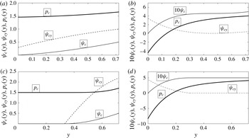
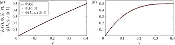
. An example of a type
 $1$
solution for a diverging pipe with
 $\unicode[STIX]{x1D70E}=0.2$
(for which the outlet radius is
 $R(L)=1.2$
) and inlet swirl ratio
 $\unicode[STIX]{x1D714}=1$
is shown in figure 1(a). For this case the centreline axial velocity is
 $\unicode[STIX]{x1D713}_{cy}(0)=0.295$
. The streamfunction
 $\unicode[STIX]{x1D713}_{c}(y)$
, the axial velocity
 $\unicode[STIX]{x1D713}_{cy}(y)$
and the pressure
 $p_{c}(y)$
are monotonically increasing with
 $y$
. For a long pipe, type
 $1$
solutions of the columnar SLE problem (3.7) and (3.8) correspond to solutions of the SLE (PDE) problem (3.4) and (3.5) that describe a decelerated flow around the centreline all along the pipe.
Four types of solutions of the columnar SLE problem (3.7) with (3.8). Here pipe is diverging with
 $\unicode[STIX]{x1D70E}=0.2$
. (a) Type
 $1$
is a solution with
 $0<\unicode[STIX]{x1D713}_{cy}(0)<1$
; solution shown is for
 $\unicode[STIX]{x1D714}=1$
. (b) Type
 $2$
is a solution with
 $\unicode[STIX]{x1D713}_{cy}(0)>1$
; solution shown is for
 $\unicode[STIX]{x1D714}=2$
. (c) Type
 $3$
is a solution with a centreline stagnation zone; solution shown is for
 $\unicode[STIX]{x1D714}=2$
. (d) Type
 $4$
is a solution with a wall quasi-stagnation zone; solution shown is for
 $\unicode[STIX]{x1D714}=2$
. In each panel,
 $\unicode[STIX]{x1D713}_{c}(y)$
is the streamfunction solution of the columnar SLE problem (3.7) with (3.8) (the thin solid line),
 $\unicode[STIX]{x1D713}_{cy}(y)$
is the resulting axial velocity (the dashed line) and
 $p_{c}(y)$
is the resulting pressure distribution according to (3.10) (the heavy solid line).

Type
 $2$
solution is characterized by
 $\unicode[STIX]{x1D713}_{cy}(0)>1$
, where again the centreline axial velocity
 $\unicode[STIX]{x1D713}_{cy}(0)$
is unknown and found as part of solution iterations until convergence with
 $\unicode[STIX]{x1D713}_{c}((1+\unicode[STIX]{x1D70E})^{2}/2)=1/2$
is achieved. For this solution, the centreline pressure is
 $p_{c}(0)=3/2-\unicode[STIX]{x1D713}_{cy}^{2}(0)/2<1$
. An example of a type
 $2$
solution for a diverging pipe with
 $\unicode[STIX]{x1D70E}=0.2$
(
 $R(L)=1.2$
) and inlet swirl ratio
 $\unicode[STIX]{x1D714}=2$
is shown in figure 1(b). Here the centreline axial velocity is
 $\unicode[STIX]{x1D713}_{cy}(0)=3.457$
. In this case, the streamfunction
 $\unicode[STIX]{x1D713}_{c}(y)$
and pressure
 $p_{c}(y)$
are monotonically increasing with
 $y$
, but the axial velocity
 $\unicode[STIX]{x1D713}_{cy}(y)$
reaches a minimum at
 $y\sim 0.4$
. For a long pipe, type
 $2$
solutions of the columnar SLE problem (3.7) and (3.8) correspond to solutions of the SLE (PDE) problem (3.4) and (3.5) that describe an accelerated flow around the centreline all along the pipe.
Type
 $3$
solution is characterized by a stagnation zone around the centreline with
 $\unicode[STIX]{x1D713}_{c}(y)=\unicode[STIX]{x1D713}_{cy}(y)=0$
for
 $0\leqslant y\leqslant y_{0}$
, where the size of the zone satisfies
 $0<y_{0}<(1+\unicode[STIX]{x1D70E})^{2}/2$
and is unknown and must be found as part of solution iterations until convergence with the wall condition
 $\unicode[STIX]{x1D713}_{c}((1+\unicode[STIX]{x1D70E})^{2}/2)=1/2$
is achieved. The solution of the columnar SLE (3.7) with (3.8) is sought in the range
 $y_{0}\leqslant y\leqslant (1+\unicode[STIX]{x1D70E})^{2}/2$
with continuous interface conditions
 $\unicode[STIX]{x1D713}_{c}(y_{0})=\unicode[STIX]{x1D713}_{cy}(y_{0})=0$
. In addition, from Bernoulli’s law along the pipe centreline, the centreline pressure is
 $p_{c}(y)=3/2$
for the whole range
 $0\leqslant y\leqslant y_{0}$
and the initial condition for pressure equation is
 $p_{c}(y_{0})=3/2$
. An example of a type
 $3$
solution for a diverging pipe with
 $\unicode[STIX]{x1D70E}=0.2$
and inlet swirl ratio
 $\unicode[STIX]{x1D714}=2$
is shown in figure 1(c). Here we find that
 $y_{0}=0.332$
. In the stagnation zone around the centreline, the streamfunction is zero,
 $\unicode[STIX]{x1D713}_{c}(y)=0$
, the axial velocity is zero,
 $\unicode[STIX]{x1D713}_{cy}(y)=0$
and pressure is constant,
 $p_{c}(y)=3/2$
. The streamfunction
 $\unicode[STIX]{x1D713}_{c}(y)$
, the axial velocity
 $\unicode[STIX]{x1D713}_{cy}(y)$
and the pressure
 $p_{c}(y)$
increase monotonically outside the stagnation zone. Specifically, the axial velocity grows from zero at the stagnation zone interface to above
 $1$
near the wall to maintain same volumetric flux as that at the inlet. For a long pipe, type
 $3$
solutions of the columnar SLE problem (3.7) and (3.8) represent solutions of the SLE (PDE) problem (3.4) and (3.5) with an outlet that contains a finite-size stagnation zone around the centreline of radial width
 $\sqrt{2y_{0}}$
. These solutions correspond to steady vortex-breakdown states of the SLE (PDE) problem with a centreline stagnation zone that starts inside the domain.
Type
 $4$
solution is characterized by a quasi-stagnation zone with
 $\unicode[STIX]{x1D713}_{c}(y)=1/2$
and
 $\unicode[STIX]{x1D713}_{cy}(y)=0$
for the range
 $y_{w}\leqslant y\leqslant (1+\unicode[STIX]{x1D70E})^{2}/2$
, where the zone size satisfies
 $0<y_{w}<(1+\unicode[STIX]{x1D70E})^{2}/2$
and is unknown and must be found as part of solution iterations. The solution of the columnar SLE is sought in the range
 $0\leqslant y\leqslant y_{w}$
with continuous interface conditions
 $\unicode[STIX]{x1D713}_{c}(y_{w})=1/2$
and
 $\unicode[STIX]{x1D713}_{cy}(y_{w})=0$
. In this case the equation is integrated backwards from
 $y_{w}$
to zero with repeated iterations until the centreline condition
 $\unicode[STIX]{x1D713}_{c}(0)=0$
is satisfied. It should be clarified that the axial and radial velocities are zero in the range
 $y_{w}\leqslant y\leqslant (1+\unicode[STIX]{x1D70E})^{2}/2$
. However, the circulation and the circumferential velocity do not vanish in this range. There,
 $K(y)=\unicode[STIX]{x1D714}$
and
 $v(y)=\unicode[STIX]{x1D714}/\sqrt{2y}$
. The interface pressure
 $p_{c}(y_{w})$
for a type
 $4$
solution is determined in the following way. Along the pipe wall
 $H(1/2)=3/2+\unicode[STIX]{x1D714}^{2}$
and
 $K(1/2)=\unicode[STIX]{x1D714}$
. Then,
 $v((1+\unicode[STIX]{x1D70E})^{2}/2)=\unicode[STIX]{x1D714}/(1+\unicode[STIX]{x1D70E})$
and
 $v(y_{w})=\unicode[STIX]{x1D714}/\sqrt{2y_{w}}$
. From Bernoulli’s law along the streamline
 $\unicode[STIX]{x1D713}=1/2$
connecting the inlet wall to
 $y=y_{w}$
at the outlet, we find that the interface pressure is
 $p_{c}(y_{w})=H(1/2)-(1/2)v^{2}(y_{w})=3/2+\unicode[STIX]{x1D714}^{2}-\unicode[STIX]{x1D714}^{2}/4y_{w}$
. An example of a type
 $4$
solution for a diverging pipe with
 $\unicode[STIX]{x1D70E}=0.2$
and inlet swirl ratio
 $\unicode[STIX]{x1D714}=2$
is shown in figure 1(d). Here we find that
 $y_{w}=0.300$
. In the wall quasi-stagnation zone,
 $\unicode[STIX]{x1D713}_{c}(y)=1/2$
, the axial velocity is zero,
 $\unicode[STIX]{x1D713}_{cy}(y)=0$
, but the pressure is not constant. Outside the zone, the streamfunction
 $\unicode[STIX]{x1D713}_{c}(y)$
and pressure
 $p_{c}(y)$
are monotonically increasing and the axial velocity is decreasing with the increase of
 $y$
. For a long pipe, type
 $4$
solutions of the columnar SLE problem (3.7) and (3.8) represent solutions of the SLE (PDE) problem (3.4) and (3.5) with an outlet state that contains a finite-size, zero axial and zero radial velocity, (quasi-stagnation) zone attached to the pipe wall. These solutions correspond to steady wall-separation states of the SLE (PDE) problem with a wall quasi-stagnation zone that starts inside the domain.
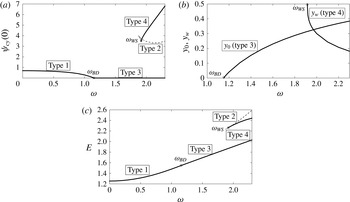
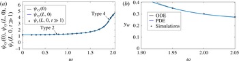
The results of successive computations for a diverging pipe with
 $\unicode[STIX]{x1D70E}=0.2$
in the range of inlet swirl ratio
 $0\leqslant \unicode[STIX]{x1D714}\leqslant 2.3$
are summarized in the bifurcation diagram of solutions of the columnar SLE problem, see figure 2. In figure 2(a), the horizontal axis is the inlet swirl ratio
 $\unicode[STIX]{x1D714}$
and the vertical axis is the value of the centreline axial velocity
 $\unicode[STIX]{x1D713}_{cy}(0)$
of each solution type. This is a representative parameter of the various solutions.
Bifurcation diagrams of solutions of the columnar SLE problem (3.7) with (3.8) for a diverging pipe with
 $\unicode[STIX]{x1D70E}=0.2$
and the range of swirl ratio
 $0\leqslant \unicode[STIX]{x1D714}\leqslant 2.3$
. (a)
 $\unicode[STIX]{x1D713}_{cy}(0)$
of the various solution types as a function of
 $\unicode[STIX]{x1D714}$
; (b) separation zone sizes
 $y_{0}$
(for type
 $3$
solutions) and
 $y_{w}$
(for type
 $4$
solutions) as a function of
 $\unicode[STIX]{x1D714}$
; (c)
 $E$
as a function of
 $\unicode[STIX]{x1D714}$
for the various types of solutions. In all panels, the heavy solid lines represent type
 $1$
,
 $3$
and
 $4$
solutions, the dash line represents type
 $2$
solutions and the thin solid line represents non-physical solutions. The circles mark the special swirl levels
 $\unicode[STIX]{x1D714}_{BD}$
and
 $\unicode[STIX]{x1D714}_{WS}$
.

It can be seen that states with decelerated flow at the centreline (type
 $1$
solutions of the columnar problem; the heavy solid line) exist and are unique in the range
 $0\leqslant \unicode[STIX]{x1D714}<\unicode[STIX]{x1D714}_{BD}$
, where for a diverging pipe with
 $\unicode[STIX]{x1D70E}=0.2$
,
 $\unicode[STIX]{x1D714}_{BD}=1.151$
. The value of
 $\unicode[STIX]{x1D713}_{cy}(0)$
of these solutions decreases to
 $0$
as
 $\unicode[STIX]{x1D714}$
is increased from zero toward
 $\unicode[STIX]{x1D714}_{BD}$
. This branch of solutions is followed by a branch of centreline breakdown states (type
 $3$
solutions) in the range
 $\unicode[STIX]{x1D714}\geqslant \unicode[STIX]{x1D714}_{BD}$
for which
 $\unicode[STIX]{x1D713}_{cy}(0)=0$
. The special level
 $\unicode[STIX]{x1D714}_{BD}$
is the first inlet swirl ratio for the onset of a stagnation zone around the centreline and of vortex-breakdown states (it is marked by a circle in all panels). In addition, the size of the stagnation zone around the centreline,
 $y_{0}$
, increases from zero as the inlet swirl ratio
 $\unicode[STIX]{x1D714}$
is increased above
 $\unicode[STIX]{x1D714}_{BD}$
, see figure 2(b). Specifically, the type
 $3$
solutions are also unique solutions in the range
 $\unicode[STIX]{x1D714}_{BD}\leqslant \unicode[STIX]{x1D714}\leqslant \unicode[STIX]{x1D714}_{WS}$
, where for a diverging pipe with
 $\unicode[STIX]{x1D70E}=0.2$
,
 $\unicode[STIX]{x1D714}_{WS}=1.916$
.
Additional solutions of accelerated flow at the centreline (type
 $2$
; the dashed line) and of wall separation (type
 $4$
; the heavy solid line) appear at swirl ratios above the second special swirl level
 $\unicode[STIX]{x1D714}_{WS}$
. The special level
 $\unicode[STIX]{x1D714}_{WS}$
is the first inlet swirl ratio for the onset of a quasi-stagnation zone near the wall and of wall-separation states (it is also marked by a circle in all panels). The type
 $4$
solutions are characterized by a decreasing value of the interface position
 $y_{w}$
with increase of
 $\unicode[STIX]{x1D714}$
above
 $\unicode[STIX]{x1D714}_{WS}$
, see figure 2(b). We would like to comment that in the range of swirl ratio
 $\unicode[STIX]{x1D714}_{\unicode[STIX]{x1D70E}}^{\ast }\leqslant \unicode[STIX]{x1D714}\leqslant \unicode[STIX]{x1D714}_{WS}$
type
 $2$
and type
 $4$
solutions are connected by solutions with
 $\unicode[STIX]{x1D713}>1/2$
in some range of
 $y$
(the thin solid line). For
 $\unicode[STIX]{x1D70E}=0.2$
, we find that
 $\unicode[STIX]{x1D714}_{\unicode[STIX]{x1D70E}}^{\ast }=1.87$
. However, these solutions do not satisfy the condition (3.3) and therefore are not physical and are not considered in the analysis.
We also note that within the range of swirl ratios and pipe divergence parameters studied we did not find additional solutions of the columnar SLE problem (3.7) with (3.8). Although not proven analytically, the existence of such additional solutions within this range is highly unlikely.
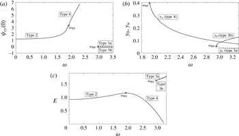
Bifurcation diagrams of solutions of the columnar SLE problem (3.7) with (3.8) for
 $\unicode[STIX]{x1D70E}=-0.1$
and the range of swirl ratio
 $0\leqslant \unicode[STIX]{x1D714}\leqslant 3.3$
. (a)
 $\unicode[STIX]{x1D713}_{cy}(0)$
of the various solution types as a function of
 $\unicode[STIX]{x1D714}$
; (b) separation zone sizes
 $y_{0}$
(for type
 $3$
solutions) and
 $y_{w}$
(for type
 $4$
solutions) as a function of
 $\unicode[STIX]{x1D714}$
; (c)
 $E$
as a function of
 $\unicode[STIX]{x1D714}$
.

The computed values of the columnar functional
 $E(\unicode[STIX]{x1D713}_{c};\unicode[STIX]{x1D714};\unicode[STIX]{x1D70E})$
according to (3.9) of the various types of solutions for a diverging pipe with
 $\unicode[STIX]{x1D70E}=0.2$
are described in figure 2(c). This figure shows that the line of
 $E(\unicode[STIX]{x1D713}_{c};\unicode[STIX]{x1D714};\unicode[STIX]{x1D70E})$
of decelerated flow states (type
 $1$
solutions) increases monotonically as
 $\unicode[STIX]{x1D714}$
increases from
 $0$
to
 $\unicode[STIX]{x1D714}_{BD}=1.151$
and is continuously followed by a monotonically increasing line of
 $E(\unicode[STIX]{x1D713}_{c};\unicode[STIX]{x1D714};\unicode[STIX]{x1D70E})$
of the breakdown states (type
 $3$
solutions). The lines of
 $E(\unicode[STIX]{x1D713}_{c};\unicode[STIX]{x1D714};\unicode[STIX]{x1D70E})$
of accelerated flows (type
 $2$
solutions) and wall-separation states (type
 $4$
solutions) also increase monotonically with
 $\unicode[STIX]{x1D714}$
. Similar results are found for other values of diverging pipes with
 $\unicode[STIX]{x1D70E}>0$
. It is concluded that in the case of a diverging pipe, the type
 $1$
solutions followed by the type
 $3$
solutions are global minimum states of
 $E$
of the columnar SLE problem, the type
 $4$
solutions are local minimum states of
 $E$
and the type
 $2$
solutions (with the highest values of
 $E$
) are min–max states of
 $E$
. According to § 3, only the global and local minimum states of
 $E$
of the columnar SLE problem represent outlet states of a swirling flow in a long diverging pipe.
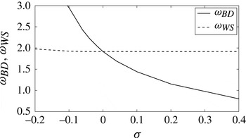
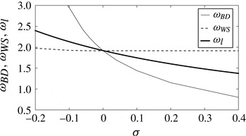
The critical swirls for vortex-breakdown states,
 $\unicode[STIX]{x1D714}_{BD}$
, and for wall-separation states,
 $\unicode[STIX]{x1D714}_{WS}$
, as a function of
 $\unicode[STIX]{x1D70E}$
.

The results of computations for a contracting pipe with
 $\unicode[STIX]{x1D70E}=-0.1$
in the range
 $0\leqslant \unicode[STIX]{x1D714}\leqslant 3.5$
are summarized in the bifurcation diagram of solutions of the columnar SLE problem, see figure 3. As before, in figure 3(a), the horizontal axis is the inlet swirl ratio
 $\unicode[STIX]{x1D714}$
and the vertical axis is the value of the centreline velocity
 $\unicode[STIX]{x1D713}_{cy}(0)$
of each solution type. It can be seen that only states with accelerated flow along the centreline (type
 $2$
solutions of the columnar problem; the heavy solid line) exist in the range
 $0\leqslant \unicode[STIX]{x1D714}<\unicode[STIX]{x1D714}_{WS}$
, where for a contracting pipe with
 $\unicode[STIX]{x1D70E}=-0.1$
,
 $\unicode[STIX]{x1D714}_{WS}=1.925$
. The values of
 $\unicode[STIX]{x1D713}_{cy}(0)$
of these solutions increase above
 $1$
as
 $\unicode[STIX]{x1D714}$
is increased toward
 $\unicode[STIX]{x1D714}_{WS}$
. This branch of solutions is followed by a branch of wall-separation states (type
 $4$
solutions) with a quasi-stagnation zone in the range
 $\unicode[STIX]{x1D714}\geqslant \unicode[STIX]{x1D714}_{WS}$
for which
 $\unicode[STIX]{x1D713}_{cy}(0)$
continues to increase with
 $\unicode[STIX]{x1D714}$
. Again, the special swirl level
 $\unicode[STIX]{x1D714}_{WS}$
is the first inlet swirl ratio for the onset of a quasi-stagnation zone near the wall and of wall-separation states (it is marked by a circle in all panels). In addition, the interface position
 $y_{w}$
of type
 $4$
solutions decreases from
 $(1+\unicode[STIX]{x1D70E})^{2}/2=0.405$
as
 $\unicode[STIX]{x1D714}$
is increased above
 $\unicode[STIX]{x1D714}_{WS}$
, see figure 3(b). Specifically, the type
 $4$
solutions are also unique solutions in the range
 $\unicode[STIX]{x1D714}_{WS}\leqslant \unicode[STIX]{x1D714}\leqslant \unicode[STIX]{x1D714}_{BD}$
, where for
 $\unicode[STIX]{x1D70E}=-0.1$
,
 $\unicode[STIX]{x1D714}_{BD}=2.95$
. Additional solutions of breakdown states (of types 3a, the dashed line, and 3b, the solid line) with a centreline stagnation zone appear at swirl ratios above the swirl level
 $\unicode[STIX]{x1D714}_{BD}$
(see figure 3
a). Again,
 $\unicode[STIX]{x1D714}_{BD}$
is the first swirl for the onset of breakdown states. The type 3a solutions are characterized by a decreasing size of the stagnation zone
 $y_{0}$
with increase of
 $\unicode[STIX]{x1D714}$
above
 $\unicode[STIX]{x1D714}_{BD}$
while the type 3b solutions have an increasing size of
 $y_{0}$
(figure 3
b).
We again note that within the range of swirl ratios and pipe contraction parameters studied we did not find additional solutions of the columnar SLE problem (3.7) with (3.8).
The computed values of the columnar functional
 $E(\unicode[STIX]{x1D713}_{c};\unicode[STIX]{x1D714};\unicode[STIX]{x1D70E})$
for the various types of solutions in a contracting pipe with
 $\unicode[STIX]{x1D70E}=-0.1$
are described in figure 3(c). This figure shows that the line of
 $E(\unicode[STIX]{x1D713}_{c};\unicode[STIX]{x1D714};\unicode[STIX]{x1D70E})$
of the accelerated flow states (type
 $2$
solutions) increases monotonically as
 $\unicode[STIX]{x1D714}$
increases from
 $0$
to
 $\unicode[STIX]{x1D714}_{WS}=1.925$
and is continuously followed by a decreasing line of
 $E(\unicode[STIX]{x1D713}_{c};\unicode[STIX]{x1D714};\unicode[STIX]{x1D70E})$
of the wall-separation states (type
 $4$
solutions). The lines of
 $E(\unicode[STIX]{x1D713}_{c};\unicode[STIX]{x1D714};\unicode[STIX]{x1D70E})$
of the breakdown states (type 3a and type 3b solutions) also increase monotonically with
 $\unicode[STIX]{x1D714}>2.95$
. Similar results are found for other values of a contracting pipe with
 $\unicode[STIX]{x1D70E}<0$
. It is concluded that in the case of a contracting pipe, the type
 $2$
solutions followed by the type
 $4$
solutions are global minimum states of
 $E$
, the type 3b solutions are local minimum states of
 $E$
and the type 3a solutions (with the highest values of
 $E$
) are min–max states of
 $E$
. According to § 3, only the global and local minimum states of
 $E$
of the columnar SLE problem represent outlet states of a swirling flow in a long contracting pipe.
The above computations demonstrate that for each geometry parameter
 $\unicode[STIX]{x1D70E}$
there exist two special levels of the incoming flow swirl ratio, one for the first appearance of vortex-breakdown (type 3) states,
 $\unicode[STIX]{x1D714}_{BD}$
, and the other for the first appearance of wall-separation (type 4) states,
 $\unicode[STIX]{x1D714}_{WS}$
. These special swirl ratios as a function of
 $\unicode[STIX]{x1D70E}$
in the range
 $-0.2\leqslant \unicode[STIX]{x1D70E}\leqslant 0.4$
are shown in figure 4. It is found that for a diverging pipe vortex-breakdown states first appear as swirl is increased from zero. Also,
 $\unicode[STIX]{x1D714}_{BD}$
decreases significantly with the increase of
 $\unicode[STIX]{x1D70E}$
while
 $\unicode[STIX]{x1D714}_{WS}$
stays constant,
 $\unicode[STIX]{x1D714}_{WS}=1.9159$
. On the other hand, for a contracting pipe, wall-separation states first appear with an increase of
 $\unicode[STIX]{x1D714}$
from zero. In this case,
 $\unicode[STIX]{x1D714}_{BD}$
increases significantly with the decrease of
 $\unicode[STIX]{x1D70E}$
from zero. It shows that, with increase of inlet swirl ratio, decelerated flow and breakdown states dominate flow dynamics in a diverging pipe while accelerated flow and wall-separation states govern flow dynamics in a contracting pipe.
5 Bifurcation diagram of swirling flow states in a pipe
The results from §§ 3 and 4 show that for a long pipe, global and local minimum states of
 ${\mathcal{E}}(\unicode[STIX]{x1D713}_{s};\unicode[STIX]{x1D714};\unicode[STIX]{x1D70E})$
(solutions of the SLE (PDE) problem (3.4) with (3.5); also steady-state solutions of the unsteady problem (2.1) and (2.2)) are governed by outlet states that are respectively global and local minimum states of
 $E(\unicode[STIX]{x1D713}_{c};\unicode[STIX]{x1D714};\unicode[STIX]{x1D70E})$
) (solutions of the columnar SLE problem). We emphasize again that min–max states of
 $E(\unicode[STIX]{x1D713}_{c};\unicode[STIX]{x1D714};\unicode[STIX]{x1D70E})$
) (of the columnar SLE problem) are not outlet profiles of min–max states of
 ${\mathcal{E}}(\unicode[STIX]{x1D713}_{s};\unicode[STIX]{x1D714};\unicode[STIX]{x1D70E})$
. Therefore, in a diverging pipe with
 $\unicode[STIX]{x1D70E}>0$
, type
 $1$
decelerated flow states turning into type
 $3$
breakdown states are global minimum states of
 ${\mathcal{E}}(\unicode[STIX]{x1D713}_{s};\unicode[STIX]{x1D714};\unicode[STIX]{x1D70E})$
and type
 $4$
wall-separation states are local minimum states of
 ${\mathcal{E}}(\unicode[STIX]{x1D713}_{s};\unicode[STIX]{x1D714};\unicode[STIX]{x1D70E})$
. Following an analysis similar to that in Wang & Rusak (Reference Wang and Rusak1997a
), it can be shown that type
 $2$
accelerated flow states must exist between the global and local minimum states and are min–max states of
 ${\mathcal{E}}(\unicode[STIX]{x1D713}_{s};\unicode[STIX]{x1D714};\unicode[STIX]{x1D70E})$
. On the other hand, for a contracting pipe with
 $\unicode[STIX]{x1D70E}<0$
, type
 $2$
accelerated flow states turning into type
 $4$
wall-separation states are global minimum states of
 ${\mathcal{E}}(\unicode[STIX]{x1D713}_{s};\unicode[STIX]{x1D714};\unicode[STIX]{x1D70E})$
and type 3b breakdown states are local minimum states of
 ${\mathcal{E}}(\unicode[STIX]{x1D713}_{s};\unicode[STIX]{x1D714};\unicode[STIX]{x1D70E})$
. Again, it can be shown that type 3a breakdown states are min–max states of
 ${\mathcal{E}}(\unicode[STIX]{x1D713}_{s};\unicode[STIX]{x1D714};\unicode[STIX]{x1D70E})$
between the type
 $4$
and type 3b states.
We want to clarify that within the range of swirl levels and pipe parameters studied in the following discussion, the present solutions of the SLE (PDE) problem and the unsteady numerical simulations do not show any additional steady flow states. The flow always converged in time to either the centreline decelerated flow, accelerated flow, breakdown or the wall-separation states. Following Rusak & Wang (Reference Rusak and Wang2014), additional higher-order solutions may exist at inlet swirl levels beyond the range of values studied in this paper. These states must be additional min–max states of
 ${\mathcal{E}}(\unicode[STIX]{x1D713}_{s};\unicode[STIX]{x1D714};\unicode[STIX]{x1D70E})$
.
In addition, the inviscid-limit flow linear stability studies in Wang & Rusak (Reference Wang and Rusak1996) and in Rusak & Judd (Reference Rusak and Judd2001) and the inviscid-limit flow simulations of Rusak et al. (Reference Rusak, Wang, Xu and Taylor2012) and of Rusak & Wang (Reference Rusak and Wang2014) demonstrate that the global and local minimum solutions of
 ${\mathcal{E}}$
according to the SLE (PDE) problem are linearly stable to either infinitesimal or finite-amplitude perturbations of a given mode form. On the other hand, the min–max solutions of
 ${\mathcal{E}}$
of the SLE (PDE) problem are unstable. Within the range of inlet swirl levels studied in this paper, the present unsteady simulations also support this fundamental relationship between the linear stability analysis and energy stability.
The SLE (PDE) problem (3.4) with (3.5) is solved for various
 $\unicode[STIX]{x1D70E}$
and
 $\unicode[STIX]{x1D714}$
using the numerical method described in appendix B. Two pipe geometry profiles are used in these computations,
 $R(x)=1+(\unicode[STIX]{x1D70E}/2)[1+\sin (\unicode[STIX]{x03C0}(x/L-1/2))]$
and
 $R(x)=1+(\unicode[STIX]{x1D70E}/2)[1+\tanh (10(x-1))]$
for
 $0\leqslant x\leqslant L$
, both with
 $L=6$
. For a given geometry parameter
 $\unicode[STIX]{x1D70E}$
, a steady-state solution
 $\unicode[STIX]{x1D713}_{s}(x,y)$
has been first established at
 $\unicode[STIX]{x1D714}=0$
, and then, through a successive increase of
 $\unicode[STIX]{x1D714}$
in small steps, steady-state solutions
 $\unicode[STIX]{x1D713}_{s}(x,y)$
are found at higher values of
 $\unicode[STIX]{x1D714}$
. In this way, for a diverging pipe with
 $\unicode[STIX]{x1D70E}>0$
, branches of type
 $1$
solutions (decelerated flow along the centreline) followed by type
 $3$
solutions (vortex-breakdown states) of the SLE (PDE) problem have been established. For a contracting pipe with
 $\unicode[STIX]{x1D70E}<0$
, branches of type
 $2$
solutions (accelerated flow along the centreline) followed by type
 $4$
solutions (wall-separation states) of the SLE (PDE) problem have also been found. In addition, in order to determine solutions of type
 $2$
and
 $4$
when
 $\unicode[STIX]{x1D70E}>0$
, a type
 $4$
solution of the problem with
 $\unicode[STIX]{x1D70E}=0$
at
 $\unicode[STIX]{x1D714}$
that is slightly greater than
 $\unicode[STIX]{x1D714}_{WS}$
(according to figure 4) has been formed. Through a successive increase of
 $\unicode[STIX]{x1D70E}$
in small steps, type
 $4$
solutions are found at a desired value of
 $\unicode[STIX]{x1D70E}>0$
. Then, by successively increasing
 $\unicode[STIX]{x1D714}$
in small steps, the branch of type
 $4$
solutions is established. By decreasing
 $\unicode[STIX]{x1D714}$
in small steps down to
 $\unicode[STIX]{x1D714}_{WS}$
, the first type
 $2$
solution is found and forms a fold point. This solution is used to establish the branch of type
 $2$
solutions for
 $\unicode[STIX]{x1D714}>\unicode[STIX]{x1D714}_{WS}$
. Similarly, in order to determine solutions of types
 $1$
and
 $3$
when
 $\unicode[STIX]{x1D70E}<0$
, a type
 $3$
solution of the problem with
 $\unicode[STIX]{x1D70E}=0$
and
 $\unicode[STIX]{x1D714}$
slightly greater than
 $\unicode[STIX]{x1D714}_{BD}(\unicode[STIX]{x1D70E}=0)$
(according to figure 4) has been formed, and through a successive increase of
 $\unicode[STIX]{x1D70E}$
in small steps, type
 $3$
solutions are found at a desired value of
 $\unicode[STIX]{x1D70E}<0$
. Then, by decreasing
 $\unicode[STIX]{x1D714}$
in small steps, the branches of type 3a and 3b solutions are found, with a fold point at
 $\unicode[STIX]{x1D714}_{BD}$
. For both pipe geometries used in the computations and for the range of inlet swirl studied, we found almost same outlet profiles (within three digits accuracy) of the computed streamfunction and of the axial velocity for all type of solutions. This indicates that when the pipe is sufficiently long the details of the pipe monotonic geometry do not affect the outlet state.
Moreover, the unsteady flow problem (2.1) and (2.2) with the assumed boundary conditions is solved for various
 $\unicode[STIX]{x1D70E}$
and
 $\unicode[STIX]{x1D714}$
using the numerical time integration scheme described in appendix A. In all simulations studied we used only one pipe geometry,
 $R(x)=1+(\unicode[STIX]{x1D70E}/2)[1+\sin (\unicode[STIX]{x03C0}(x/L-1/2))]$
with
 $L=6$
. For a given
 $\unicode[STIX]{x1D70E}$
, starting from an initial columnar state at
 $\unicode[STIX]{x1D714}=0.2$
, flow dynamics converges after long time to a time-asymptotic state
 $\unicode[STIX]{x1D713}(x,y,t\gg 1)$
that is nearly the steady state at the given
 $\unicode[STIX]{x1D70E}$
and
 $\unicode[STIX]{x1D714}=0.2$
. Then, through successively using the time-asymptotic state of a previous
 $\unicode[STIX]{x1D714}$
as an initial state and increasing
 $\unicode[STIX]{x1D714}$
in small steps, branches of time-asymptotic states
 $\unicode[STIX]{x1D713}(x,y,t\gg 1)$
of the unsteady problem (2.1) and (2.2) have been established. In this way, when
 $\unicode[STIX]{x1D70E}>0$
, branches of type
 $1$
time-asymptotic states (decelerated flow along the centreline) followed by type
 $3$
time-asymptotic states (vortex-breakdown states) are found. When
 $\unicode[STIX]{x1D70E}<0$
, branches of type
 $2$
time-asymptotic states (accelerated flow along the centreline) followed by type
 $4$
time-asymptotic states (wall-separation states) are formed. In addition, when
 $\unicode[STIX]{x1D70E}>0$
, type
 $4$
time-asymptotic states are found by initially perturbing a columnar state at
 $\unicode[STIX]{x1D70E}=0$
and
 $\unicode[STIX]{x1D714}>\unicode[STIX]{x1D714}_{WS}(\unicode[STIX]{x1D70E}=0)$
and computing flow dynamics until a type
 $4$
time-asymptotic state is established. Using this state as an initial state and successively increasing
 $\unicode[STIX]{x1D70E}$
in small steps and in time to a desired
 $\unicode[STIX]{x1D70E}>0$
, a type
 $4$
time-asymptotic state is found. Then, by increasing or decreasing
 $\unicode[STIX]{x1D714}$
in small steps, the branch of type
 $4$
time-asymptotic states is established.
We note that in the simulations no time-asymptotic states of type
 $2$
are found when
 $\unicode[STIX]{x1D70E}>0$
and no type
 $1$
and 3a states are found when
 $\unicode[STIX]{x1D70E}<0$
. This demonstrates that these states are indeed unstable, as has been mentioned above, and cannot be formed as part of time-asymptotic flow evolution. We also note that for all
 $\unicode[STIX]{x1D70E}$
the vortex-breakdown stagnation zones as well as the wall-separation quasi-stagnation zones appear naturally during the computed flow evolution to time-asymptotic states, with no special assumption in the simulation procedure. Specifically, no averaging step of computations is needed during the simulation of flow evolution, in contrast the inviscid-limit flow simulations of Rusak et al. (Reference Rusak, Wang, Xu and Taylor2012) that studied the dynamics of Lamb–Oseen vortices with small vortex cores.
5.1 Diverging pipe with
$\unicode[STIX]{x1D70E}=0.2$

Figure 5 presents representative examples of time-asymptotic states
 $\unicode[STIX]{x1D713}(x,y,t\gg 1)$
from simulations based on (2.1) and (2.2) with the assumed boundary conditions in a diverging pipe with
 $\unicode[STIX]{x1D70E}=0.2$
and
 $L=6$
. When
 $\unicode[STIX]{x1D714}=1$
, a type
 $1$
decelerated flow state along the centreline is found (figure 5
a). This flow is slightly deflected radially from the centreline. When
 $\unicode[STIX]{x1D714}=1.95$
, a type
 $3$
vortex-breakdown state is observed (figure 5
b). In this state, the breakdown, near-stagnation zone starts along the centreline at
 $x\sim 1$
and expands radially in size as flow develops towards the outlet. When
 $\unicode[STIX]{x1D714}=1.95$
, a type
 $4$
wall-separation state is also found (figure 5
c). In this state, the wall-separation, quasi-stagnation zone starts along the wall at
 $x\sim 1.6$
and expands radially from the wall as flow develops towards the outlet.
Streamfunction contours of time-asymptotic states from simulations based on (2.1) and (2.2) with the assumed boundary conditions when: (a)
 $\unicode[STIX]{x1D70E}=0.2$
and
 $\unicode[STIX]{x1D714}=1$
, a decelerated flow state along the centreline; (b)
 $\unicode[STIX]{x1D70E}=0.2$
and
 $\unicode[STIX]{x1D714}=1.95$
, a vortex-breakdown state; (c)
 $\unicode[STIX]{x1D70E}=0.2$
and
 $\unicode[STIX]{x1D714}=1.95$
, a wall-separation state. In all panels, the flow goes from left to right and there are 26 equi-spaced lines between
 $\unicode[STIX]{x1D713}=0$
and
 $\unicode[STIX]{x1D713}=0.5$
. Also, the red line in (c) represents the contour
 $\unicode[STIX]{x1D713}=0.495$
.

Figure 6 presents a comparison between the computed outlet streamfunction profile
 $\unicode[STIX]{x1D713}_{s}(L,y)$
from the steady-state solutions of the SLE (PDE) problem, the computed outlet profile
 $\unicode[STIX]{x1D713}(L,y,t\gg 1)$
from the simulated time-asymptotic states, and solutions
 $\unicode[STIX]{x1D713}_{c}(y)$
of the columnar SLE problem for the three cases shown in figure 5. It is found that these outlet profiles are similar one to the others. The solutions of the columnar SLE (ODE) problem nicely predict the outlet states of both steady-state solutions of the SLE (PDE) problem and of the time-asymptotic states from the simulations of flow dynamics. They also provide a direct indication about the flow development along the pipe.
Comparison of the streamfunction outlet profiles from steady-state solutions of the SLE problem, time-asymptotic state from simulations based on (2.1) and (2.2) with the assumed boundary conditions, and solutions of the columnar SLE problem when
 $\unicode[STIX]{x1D70E}=0.2$
,
 $L=6$
and: (a)
 $\unicode[STIX]{x1D714}=1$
, a decelerated flow state along the centreline; (b)
 $\unicode[STIX]{x1D714}=1.95$
, a vortex-breakdown state; (c)
 $\unicode[STIX]{x1D714}=1.95$
, a wall-separation state.

The bifurcation diagrams of solutions of the SLE (PDE) problem (3.4) with (3.5) (the heavy solid line) and time-asymptotic results of the simulations (circles) are shown in figure 7 for flows in a diverging pipe with
 $\unicode[STIX]{x1D70E}=0.2$
and
 $L=6$
. Also shown for reference are results of solutions of the columnar SLE problem (3.7) with (3.8) (thin line). Figure 7(a) describes the representative centreline axial velocities
 $\unicode[STIX]{x1D713}_{cy}(0)$
,
 $\unicode[STIX]{x1D713}_{sy}(L,0)$
and
 $\unicode[STIX]{x1D713}_{y}(L,0,t\gg 1)$
of the various solution types as a function of the inlet swirl ratio
 $\unicode[STIX]{x1D714}$
in the range
 $0\leqslant \unicode[STIX]{x1D714}\leqslant 1.85$
. Figure 7(b) presents these parameters as a function of
 $\unicode[STIX]{x1D714}$
in the range
 $1.85\leqslant \unicode[STIX]{x1D714}\leqslant 2.05$
. Figure 7(c) shows the separation zone sizes
 $y_{0}$
and
 $y_{w}$
as a function of
 $\unicode[STIX]{x1D714}$
. These three figures demonstrate agreement between type
 $1$
,
 $3$
and
 $4$
solutions according to the SLE (PDE) problem and simulated time-asymptotic states of the flow evolution. Also, these results are close to predictions according to the columnar SLE (ODE) problem. The small gap occurs because of pipe length that is
 $L=6$
in the SLE (PDE) problem and in the simulations, while
 $L\gg 1$
is assumed in applying solutions of the columnar SLE (ODE) problem to solutions of the SLE (PDE) problem. It is understood that this small gap decreases with increase of pipe length
 $L$
.
Bifurcation diagrams of solutions of the SLE problem (3.4) with (3.5) (the heavy solid line) and time-asymptotic results of the simulations (circles), for
 $\unicode[STIX]{x1D70E}=0.2$
and
 $L=6$
. Also shown for reference are results of solutions of the columnar SLE problem (3.7) with (3.8) (thin line); (a)
 $\unicode[STIX]{x1D713}_{cy}(0)$
,
 $\unicode[STIX]{x1D713}_{sy}(L,0)$
and
 $\unicode[STIX]{x1D713}_{y}(L,0,t\gg 1)$
of the various solution types as a function of
 $\unicode[STIX]{x1D714}$
in the range
 $0\leqslant \unicode[STIX]{x1D714}\leqslant 1.85$
; (b)
 $\unicode[STIX]{x1D713}_{cy}(0)$
,
 $\unicode[STIX]{x1D713}_{sy}(L,0)$
and
 $\unicode[STIX]{x1D713}_{y}(L,0,t\gg 1)$
of the various solution types as a function of
 $\unicode[STIX]{x1D714}$
in the range
 $1.85\leqslant \unicode[STIX]{x1D714}\leqslant 2.05$
; (c) separation zone sizes
 $y_{0}$
and
 $y_{w}$
as a function of
 $\unicode[STIX]{x1D714}$
.

The solutions of the SLE (PDE) problem in figure 7 (for flows in a diverging pipe with
 $\unicode[STIX]{x1D70E}=0.2$
and
 $L=6$
) show that decelerated flow states turn into breakdown states at
 $\unicode[STIX]{x1D714}_{BD}=1.158$
and that the branch of wall-separation states folds at
 $\unicode[STIX]{x1D714}_{WS}=1.940$
and turns into accelerated flow states. Note that as predicted, the type
 $2$
min–max solutions of the SLE (PDE) problem are indeed different from the type
 $2$
min–max solutions of the columnar SLE problem. The numerical unsteady flow simulations for the same diverging pipe demonstrate that within the range of swirl ratios studied the type 1, 3 and 4 time-asymptotic states are asymptotically stable states while the type 2 states cannot be found out of flow evolution and are therefore unstable states. The simulations also show that indeed
 $\unicode[STIX]{x1D714}_{BD}\sim 1.16$
when
 $\unicode[STIX]{x1D70E}=0.2$
and
 $L=6$
. Moreover, initializing the simulation with the time-asymptotic wall-separation state at
 $\unicode[STIX]{x1D714}=1.95$
and reducing the inlet swirl to
 $\unicode[STIX]{x1D714}=1.94$
results in a transition of the flow over time to the breakdown state at
 $\unicode[STIX]{x1D714}=1.94$
. This demonstrates that indeed
 $\unicode[STIX]{x1D714}_{WS}\sim 1.94$
for
 $\unicode[STIX]{x1D70E}=0.2$
and
 $L=6$
. Note that according to solutions of the columnar SLE problem
 $\unicode[STIX]{x1D714}_{BD}=1.151$
and
 $\unicode[STIX]{x1D714}_{WS}=1.916$
. It is expected that
 $\unicode[STIX]{x1D714}_{BD}$
and
 $\unicode[STIX]{x1D714}_{WS}$
from the SLE (PDE) solutions and from the simulations approach the columnar SLE results as
 $L$
is increased much above six. Figure 7 demonstrates that the decelerated flow states followed by the vortex-breakdown states dominate the flow dynamics in a diverging pipe.
5.2 Contracting pipe with
$\unicode[STIX]{x1D70E}=-0.1$

Figure 8 presents representative examples of time-asymptotic states from simulations based on the unsteady problem (2.1) and (2.2) with the assumed boundary conditions for flows in a contracting pipe with
 $\unicode[STIX]{x1D70E}=-0.1$
and
 $L=6$
. When
 $\unicode[STIX]{x1D714}=1$
, a type
 $2$
accelerated flow state along the centreline is found (figure 8
a). This flow is slightly deflected radially towards the centreline and away from the wall. When
 $\unicode[STIX]{x1D714}=1.95$
, a type
 $4$
wall-separation state is observed (figure 8
b). In this state, the quasi-stagnation wall-separation zone starts along the wall at
 $x\sim 1.3$
and expands radially in size from the wall as flow develops towards the outlet.
Streamfunction contours of time-asymptotic states from simulations based on (2.1) and (2.2) with the assumed boundary conditions when
 $\unicode[STIX]{x1D70E}=-0.1$
,
 $L=6$
and: (a)
 $\unicode[STIX]{x1D714}=1$
, an accelerated flow state along the centreline; (b)
 $\unicode[STIX]{x1D714}=1.95$
, a wall-separation state. In all panels, the flow goes from left to right and there are 26 equi-spaced lines between
 $\unicode[STIX]{x1D713}=0$
and
 $\unicode[STIX]{x1D713}=0.5$
. Also, the red line in (b) represents the contour
 $\unicode[STIX]{x1D713}=0.497$
.

Figure 9 presents a comparison between the computed outlet streamfunction profiles
 $\unicode[STIX]{x1D713}_{s}(L,y)$
from the solutions of the SLE (PDE) problem,
 $\unicode[STIX]{x1D713}(L,y,t\gg 1)$
from the simulated time-asymptotic states, and
 $\unicode[STIX]{x1D713}_{c}(y)$
from the solutions of the columnar SLE problem for the two states shown in figure 8. It is found that these outlet streamfunction profiles are similar one to the others. As in the case of a diverging pipe, the solutions of the columnar SLE (ODE) problem nicely predict the outlet states of both the steady-state solutions of the SLE (PDE) problem and of the time-asymptotic states from the simulations of flow dynamics. They also provide a direct indication about the flow development along the pipe.
Comparison of the streamfunction outlet profiles from steady-state solutions of the SLE problem, time-asymptotic state from simulations based on (2.1) and (2.2) with the assumed boundary conditions, and solutions of the columnar SLE problem when: (a)
 $\unicode[STIX]{x1D70E}=-0.1$
and
 $\unicode[STIX]{x1D714}=1$
, an accelerated flow state along the centreline; (b)
 $\unicode[STIX]{x1D70E}=-0.1$
and
 $\unicode[STIX]{x1D714}=1.95$
, a wall-separation state.

The bifurcation diagrams of solutions of the SLE (PDE) problem (3.4) with (3.5) (the heavy solid line) and time-asymptotic results of the simulations (circles) are shown in figure 10 for flows in a contracting pipe with
 $\unicode[STIX]{x1D70E}=-0.1$
and
 $L=6$
. Also shown for reference are results of solutions of the columnar SLE problem (3.7) with (3.8) (thin line). Figure 10(a) describes the representative centreline velocities
 $\unicode[STIX]{x1D713}_{cy}(0)$
,
 $\unicode[STIX]{x1D713}_{sy}(L,0)$
and
 $\unicode[STIX]{x1D713}_{y}(L,0,t\gg 1)$
of the various solution types as a function of the inlet swirl ratio
 $\unicode[STIX]{x1D714}$
in the range
 $0\leqslant \unicode[STIX]{x1D714}\leqslant 2.05$
. Figure 10(b) shows the outlet position of the separation zone interface of the wall-separation states,
 $y_{w}$
, as a function of
 $\unicode[STIX]{x1D714}$
. These two figures demonstrate agreement between type
 $2$
and
 $4$
solutions according to the SLE (PDE) problem and the simulated time-asymptotic states of the flow evolution. Also, these results are close to prediction according to the columnar SLE (ODE) problem. The small gap near
 $\unicode[STIX]{x1D714}=1.92$
occurs because of pipe length that is
 $L=6$
in the SLE (PDE) problem and in the unsteady simulations, while
 $L\gg 1$
is assumed in applying solutions of the columnar SLE problem to solutions of the SLE (PDE) problem. Again, it is expected that this gap decreases with increase of
 $L$
.
Bifurcation diagrams of solutions of the SLE problem (3.4) with (3.5) (the heavy solid line) and time-asymptotic results of the simulations (circles), for
 $\unicode[STIX]{x1D70E}=-0.1$
and
 $L=6$
. Also shown for reference are results of solutions of the columnar SLE problem (3.7) with (3.8) (thin line); (a)
 $\unicode[STIX]{x1D713}_{cy}(0)$
,
 $\unicode[STIX]{x1D713}_{sy}(L,0)$
and
 $\unicode[STIX]{x1D713}_{y}(L,0,t\gg 1)$
of the various solution types as a function of
 $\unicode[STIX]{x1D714}$
in the range
 $0\leqslant \unicode[STIX]{x1D714}\leqslant 2.05$
; (b) separation zone size of type 4 states,
 $y_{w}$
, as a function of inlet swirl ratio,
 $\unicode[STIX]{x1D714}$
.

The solutions of the SLE (PDE) problem in figure 10 for flows in a contracting pipe with
 $\unicode[STIX]{x1D70E}=-0.1$
and
 $L=6$
show that type
 $2$
accelerated flow states turn into type
 $4$
wall-separation states at
 $\unicode[STIX]{x1D714}_{WS}=1.918$
. The numerical unsteady flow simulations for contracting pipes demonstrate that within the range of swirl ratios studied the type 2 and 4 time-asymptotic states are asymptotically stable states. The unsteady simulations also demonstrate that indeed
 $\unicode[STIX]{x1D714}_{WS}\sim 1.92$
when
 $\unicode[STIX]{x1D70E}=-0.1$
and
 $L=6$
. Note that according to solutions of the columnar SLE problem
 $\unicode[STIX]{x1D714}_{WS}=1.925$
. It is understood that
 $\unicode[STIX]{x1D714}_{WS}$
from the SLE (PDE) solutions and from the unsteady simulations approach the columnar SLE results as
 $L$
is increased much above six. Figure 10 demonstrates that the accelerated flow states along the centreline followed by the wall-separation states dominate the flow dynamics in a contracting pipe.
6 Uniqueness of steady flow state when
$0\leqslant \unicode[STIX]{x1D714}<\unicode[STIX]{x1D714}_{l}(D)$

The results of § 5 demonstrate that the unsteady flow problem (2.1)–(2.2) with the assumed boundary conditions has a unique steady-state solution in the range of incoming swirl ratio
 $0\leqslant \unicode[STIX]{x1D714}<\unicode[STIX]{x1D714}_{WS}$
when
 $\unicode[STIX]{x1D70E}>0$
and in the range
 $0\leqslant \unicode[STIX]{x1D714}<\unicode[STIX]{x1D714}_{BD}$
when
 $\unicode[STIX]{x1D70E}<0$
(see figure 4).
In this section we prove the uniqueness of the steady-state flow problem described by the SLE (PDE) (3.4) and boundary conditions (3.5) in a definite range of the incoming swirl ratios
 $0\leqslant \unicode[STIX]{x1D714}<\unicode[STIX]{x1D714}_{l}(D)$
. Here
 $D$
is the flow domain,
 $D\equiv \{(x,y)\in \mathbb{R}^{2}~|~0\leqslant x\leqslant L,~0\leqslant y\leqslant R^{2}(x)/2\}$
. Assuming
 $\unicode[STIX]{x1D713}_{s}(x,y)$
is a solution of (3.4) and (3.5), a perturbed solution is given by
 $\unicode[STIX]{x1D713}_{s}^{\ast }(x,y)=\unicode[STIX]{x1D713}_{s}(x,y)+\overline{\unicode[STIX]{x1D713}}(x,y)$
where the perturbation streamfunction
 $\overline{\unicode[STIX]{x1D713}}(x,y)$
and related
 $\unicode[STIX]{x1D714}_{l}(D)$
are found from solving the following eigenvalue problem:
 $$\begin{eqnarray}\displaystyle \overline{\unicode[STIX]{x1D713}}_{yy}+{\displaystyle \frac{\overline{\unicode[STIX]{x1D713}}_{xx}}{2y}}+2\unicode[STIX]{x1D714}_{l}^{2}(D){\displaystyle \frac{\overline{\unicode[STIX]{x1D713}}}{y}}=0 & & \displaystyle\end{eqnarray}$$
in the domain
 $D$
with the homogeneous boundary conditions:
 $$\begin{eqnarray}\displaystyle \left.\begin{array}{@{}c@{}}\displaystyle \overline{\unicode[STIX]{x1D713}}(0,y)=0\quad \text{for }0\leqslant y\leqslant 1/2,\quad \overline{\unicode[STIX]{x1D713}}_{x}(L,y)=0\quad \text{for }0\leqslant y\leqslant R^{2}(L)/2,\\ \displaystyle \overline{\unicode[STIX]{x1D713}}(x,0)=0\quad \text{and}\quad \overline{\unicode[STIX]{x1D713}}(x,R^{2}(x)/2)=0\quad \text{for }0\leqslant x\leqslant L.\end{array}\right\} & & \displaystyle\end{eqnarray}$$
The incoming limit swirl level
 $\unicode[STIX]{x1D714}_{l}(D)$
is defined as the first eigenvalue of the linearized SLE problem (6.1) and (6.2). In the following discussion, we show that when
 $0\leqslant \unicode[STIX]{x1D714}<\unicode[STIX]{x1D714}_{l}(D)$
the only solution of this problem is the trivial solution,
 $\overline{\unicode[STIX]{x1D713}}=0$
, and then the solution
 $\unicode[STIX]{x1D713}_{s}(x,y)$
is unique.
The eigenvalues
 $\unicode[STIX]{x1D714}_{l}(D)$
of a swirling flow in a pipe where
 $R(x)=1+(\unicode[STIX]{x1D70E}/2)[1+\tanh (10(x-1))]$
and in a pipe where
 $R(x)=1+(\unicode[STIX]{x1D70E}/2)[1+\sin (\unicode[STIX]{x03C0}(x/L-1/2))]$
, for
 $0\leqslant x\leqslant L$
, both with
 $L=6$
and with various values of
 $\unicode[STIX]{x1D70E}$
, were computed numerically using a standard eigenvalue solver of (6.1) and (6.2). The resulting values of
 $\unicode[STIX]{x1D714}_{l}(D)$
as a function of
 $\unicode[STIX]{x1D70E}$
in the range
 $-0.2\leqslant \unicode[STIX]{x1D70E}\leqslant 0.4$
are numerically nearly the same for both pipe geometries (within 3 digits) and are presented in figure 11 (the solid heavy line). Also shown for comparison are the curves of
 $\unicode[STIX]{x1D714}_{BD}$
(the thin line) and
 $\unicode[STIX]{x1D714}_{WS}$
(the dash line) as function of
 $\unicode[STIX]{x1D70E}$
. We find that
 $\unicode[STIX]{x1D714}_{l}(D)=\unicode[STIX]{x1D714}_{BD}=\unicode[STIX]{x1D714}_{WS}=1.92$
when
 $\unicode[STIX]{x1D70E}=0$
(the case of a straight pipe, Rusak & Wang Reference Rusak and Wang2014). The swirl level
 $\unicode[STIX]{x1D714}_{l}(D)$
decreases with the increase of pipe divergence (when
 $\unicode[STIX]{x1D70E}>0$
) and increases with increase of size of the pipe contraction (when
 $\unicode[STIX]{x1D70E}<0$
). Also,
 $\unicode[STIX]{x1D714}_{BD}<\unicode[STIX]{x1D714}_{l}(D)<\unicode[STIX]{x1D714}_{WS}$
when
 $\unicode[STIX]{x1D70E}>0$
and
 $\unicode[STIX]{x1D714}_{WS}<\unicode[STIX]{x1D714}_{l}(D)<\unicode[STIX]{x1D714}_{BD}$
when
 $\unicode[STIX]{x1D70E}<0$
.
The critical swirl level
 $\unicode[STIX]{x1D714}_{l}(D)$
(the heavy line) as a function of
 $\unicode[STIX]{x1D70E}$
for a pipe with
 $R(x)=1+(\unicode[STIX]{x1D70E}/2)[1+\tanh (10(x-1))]$
and for a pipe with
 $R(x)=1+(\unicode[STIX]{x1D70E}/2)[1+\sin (\unicode[STIX]{x03C0}(x/L-1/2))]$
with
 $L=6$
. Also shown are the swirl levels for vortex-breakdown states,
 $\unicode[STIX]{x1D714}_{BD}$
(the thin line), and for wall-separation states,
 $\unicode[STIX]{x1D714}_{WS}$
(the dash-dot line), as a function of
 $\unicode[STIX]{x1D70E}$
.

We prove now that there exists a unique weak solution of the SLE (PDE) problem (3.4) and (3.5) in the domain
 $D$
and with the definitions (3.2) and (3.3) when
 $0\leqslant \unicode[STIX]{x1D714}<\unicode[STIX]{x1D714}_{l}(D)$
. Following Rusak & Wang (Reference Rusak and Wang2014), the swirl level
 $\unicode[STIX]{x1D714}_{l}(D)$
can also be determined by the Rayleigh quotient
 $$\begin{eqnarray}2\unicode[STIX]{x1D714}_{l}^{2}(D)=\min _{\overline{\unicode[STIX]{x1D713}}}{\displaystyle \frac{\displaystyle \int _{D}\left(\overline{\unicode[STIX]{x1D713}}_{y}^{2}+{\displaystyle \frac{\overline{\unicode[STIX]{x1D713}}_{x}^{2}}{2y}}\right)\,\text{d}x\,\text{d}y}{\displaystyle \int _{D}{\displaystyle \frac{\overline{\unicode[STIX]{x1D713}}^{2}}{y}}\,\text{d}x\,\text{d}y}}.\end{eqnarray}$$
Note that this is a weighted Poincaré inequality, where the minimization process is taken over all the test functions
 $\overline{\unicode[STIX]{x1D713}}$
that are admissible with the boundary conditions (3.5). Also, one may replace
 $D$
in (6.3) by any other bounded subdomain
 $\overline{D}$
,
 $\overline{D}\subset D$
, with piecewise-smooth boundaries and choosing
 $\overline{\unicode[STIX]{x1D713}}=0$
in the domain
 $D-\overline{D}$
. It can be shown that if
 $\overline{D}$
and
 $D$
are bounded domains with piecewise-smooth boundaries then
 $\unicode[STIX]{x1D714}_{l}(\overline{D})\geqslant \unicode[STIX]{x1D714}_{l}(D)$
. This is demonstrated in figure 11 where
 $\unicode[STIX]{x1D714}_{l}$
decreases with increase of
 $\unicode[STIX]{x1D70E}$
from negative to positive values.
In addition, the energy functional associated with the SLE (PDE) (3.4) is given from (3.6) for the case of a solid-body rotation by:
 $$\begin{eqnarray}\displaystyle {\mathcal{E}}(\unicode[STIX]{x1D713}_{s};\unicode[STIX]{x1D714};\unicode[STIX]{x1D70E})=\int _{D}\left[{\displaystyle \frac{\unicode[STIX]{x1D713}_{sy}^{2}}{2}}+{\displaystyle \frac{\unicode[STIX]{x1D713}_{sx}^{2}}{4y}}+H_{0}+2\unicode[STIX]{x1D714}^{2}\left(\unicode[STIX]{x1D713}_{s}-{\displaystyle \frac{\unicode[STIX]{x1D713}_{s}^{2}}{2y}}\right)\right]\,\text{d}x\,\text{d}y. & & \displaystyle\end{eqnarray}$$
Based on (6.3), a global minimum state of the functional (6.4) exists by using a standard compactness argument, see for example Wang & Rusak (Reference Wang and Rusak1997a
). We denote this global minimum state by
 $\unicode[STIX]{x1D713}_{g}$
. Note that we enforce
 $0\leqslant \unicode[STIX]{x1D713}_{g}\leqslant 1/2$
for correctly describing solutions with stagnation or quasi-stagnation zones; see Rusak & Wang (Reference Rusak and Wang2014).
For each function
 $0\leqslant \unicode[STIX]{x1D713}_{s}(x,y)\leqslant 1/2$
in
 $D$
, we partition the domain
 $D$
into three sets,
 $D_{\unicode[STIX]{x1D713}_{s}}^{+}\equiv \{(x,y)\in D\text{ and }0<\unicode[STIX]{x1D713}_{s}(x,y)<1/2\}$
,
 $D_{\unicode[STIX]{x1D713}_{s}}^{0}\equiv \{(x,y)\in D\text{ and }\unicode[STIX]{x1D713}_{s}(x,y)=0\}$
and
 $D_{\unicode[STIX]{x1D713}_{s}}^{1/2}\equiv \{(x,y)\in D\text{ and }\unicode[STIX]{x1D713}_{s}(x,y)=1/2\}$
. Here,
 $D_{\unicode[STIX]{x1D713}_{s}}^{0}$
and
 $D_{\unicode[STIX]{x1D713}_{s}}^{1/2}$
represent the zones of breakdown and wall separation of
 $\unicode[STIX]{x1D713}_{s}$
, respectively. For a state without any separation zone,
 $D=D_{\unicode[STIX]{x1D713}_{s}}^{+}$
. For a state with only a breakdown zone,
 $D=D_{\unicode[STIX]{x1D713}_{s}}^{+}\cup D_{\unicode[STIX]{x1D713}_{s}}^{0}$
and
 $D_{\unicode[STIX]{x1D713}_{s}}^{1/2}=0$
, while for a state with only a wall-separation zone,
 $D=D_{\unicode[STIX]{x1D713}_{s}}^{+}\cup D_{\unicode[STIX]{x1D713}_{s}}^{1/2}$
and
 $D_{\unicode[STIX]{x1D713}_{s}}^{0}=0$
. In general, for a state with both separation zones,
 $D=D_{\unicode[STIX]{x1D713}_{s}}^{+}\cup D_{\unicode[STIX]{x1D713}_{s}}^{0}\cup D_{\unicode[STIX]{x1D713}_{s}}^{1/2}$
.
The first variation of (6.4) is given by:
 $$\begin{eqnarray}\displaystyle \langle \unicode[STIX]{x1D6FF}{\mathcal{E}}(\unicode[STIX]{x1D713}_{s};\unicode[STIX]{x1D714};\unicode[STIX]{x1D70E}),\overline{\unicode[STIX]{x1D713}}\rangle & \equiv & \displaystyle \lim _{\unicode[STIX]{x1D716}\rightarrow 0}{\displaystyle \frac{1}{\unicode[STIX]{x1D716}}}\left[{\mathcal{E}}(\unicode[STIX]{x1D713}_{s}+\unicode[STIX]{x1D716}\overline{\unicode[STIX]{x1D713}};\unicode[STIX]{x1D714};\unicode[STIX]{x1D70E})-{\mathcal{E}}(\unicode[STIX]{x1D713}_{s};\unicode[STIX]{x1D714};\unicode[STIX]{x1D70E})\right]\nonumber\\ \displaystyle & = & \displaystyle \int _{D}\left[\unicode[STIX]{x1D713}_{sy}\overline{\unicode[STIX]{x1D713}}_{y}+{\displaystyle \frac{\unicode[STIX]{x1D713}_{sx}\overline{\unicode[STIX]{x1D713}}_{x}}{2y}}+2\unicode[STIX]{x1D714}^{2}\left(1-{\displaystyle \frac{\unicode[STIX]{x1D713}_{s}}{y}}\right)\overline{\unicode[STIX]{x1D713}}\right]\,\text{d}x\,\text{d}y\nonumber\\ \displaystyle & = & \displaystyle \int _{D}\left(\unicode[STIX]{x1D713}_{sy}\overline{\unicode[STIX]{x1D713}}_{y}+{\displaystyle \frac{\unicode[STIX]{x1D713}_{sx}\overline{\unicode[STIX]{x1D713}}_{x}}{2y}}\right)\,\text{d}x\,\text{d}y\nonumber\\ \displaystyle & & \displaystyle +\,2\unicode[STIX]{x1D714}^{2}\int _{D_{\unicode[STIX]{x1D713}_{s}}^{+}}\left(1-{\displaystyle \frac{\unicode[STIX]{x1D713}_{s}}{y}}\right)\overline{\unicode[STIX]{x1D713}}\,\text{d}x\,\text{d}y+2\unicode[STIX]{x1D714}^{2}\int _{D_{\unicode[STIX]{x1D713}_{s}}^{0}}(\overline{\unicode[STIX]{x1D713}})^{+}\text{d}x\,\text{d}y\nonumber\\ \displaystyle & & \displaystyle -\,2\unicode[STIX]{x1D714}^{2}\int _{D_{\unicode[STIX]{x1D713}_{s}}^{1/2}}\left(y-{\displaystyle \frac{1}{2}}\right){\displaystyle \frac{\left(-\overline{\unicode[STIX]{x1D713}}\right)^{+}}{y}}\,\text{d}x\,\text{d}y.\end{eqnarray}$$
Here, the perturbation test function
 $(\overline{\unicode[STIX]{x1D713}})^{+}$
is defined by:
 $$\begin{eqnarray}(\overline{\unicode[STIX]{x1D713}})^{+}\equiv \overline{\unicode[STIX]{x1D713}}\quad \text{if }\overline{\unicode[STIX]{x1D713}}>0\quad \text{and}\quad (\overline{\unicode[STIX]{x1D713}})^{+}\equiv 0\quad \text{if }\overline{\unicode[STIX]{x1D713}}\leqslant 0.\end{eqnarray}$$
Note that
 $(-\overline{\unicode[STIX]{x1D713}})^{+}=0$
if
 $\overline{\unicode[STIX]{x1D713}}\geqslant 0$
and
 $(-\overline{\unicode[STIX]{x1D713}})^{+}=-\overline{\unicode[STIX]{x1D713}}$
if
 $\overline{\unicode[STIX]{x1D713}}<0$
. The relationship
 $\langle \unicode[STIX]{x1D6FF}{\mathcal{E}}(\unicode[STIX]{x1D713}_{s};\unicode[STIX]{x1D714};\unicode[STIX]{x1D70E}),\overline{\unicode[STIX]{x1D713}}\rangle \geqslant 0$
for all test functions
 $\overline{\unicode[STIX]{x1D713}}$
is a definition of a solution in the weak sense. In this way, this solution is extended to include solutions with either a stagnation or a quasi-stagnation zone (Rusak & Wang Reference Rusak and Wang2014).
For each test function
 $\overline{\unicode[STIX]{x1D713}}$
that is compactly supported on
 $D_{\unicode[STIX]{x1D713}_{g}}^{+}$
, we find in the domain
 $D$
that the global minimum state
 $\unicode[STIX]{x1D713}_{g}$
satisfies
 $\langle \unicode[STIX]{x1D6FF}{\mathcal{E}}(\unicode[STIX]{x1D713}_{g};\unicode[STIX]{x1D714};\unicode[STIX]{x1D70E}),\overline{\unicode[STIX]{x1D713}}\rangle =0$
, or from (6.5):
 $$\begin{eqnarray}\int _{D}\left[\unicode[STIX]{x1D713}_{gy}\overline{\unicode[STIX]{x1D713}}_{y}+{\displaystyle \frac{\unicode[STIX]{x1D713}_{gx}\overline{\unicode[STIX]{x1D713}}_{x}}{2y}}+2\unicode[STIX]{x1D714}^{2}\left(1-{\displaystyle \frac{\unicode[STIX]{x1D713}_{g}}{y}}\right)\overline{\unicode[STIX]{x1D713}}\right]\,\text{d}x\,\text{d}y=0.\end{eqnarray}$$
Let
 $\hat{\unicode[STIX]{x1D713}}$
be a test function that is compactly supported on
 $D_{\unicode[STIX]{x1D713}_{g}}^{+}$
. Assuming
 $\unicode[STIX]{x1D713}_{s}=\unicode[STIX]{x1D713}_{g}+\hat{\unicode[STIX]{x1D713}}$
is another weak solution of the problem, we also have from (6.5):
 $$\begin{eqnarray}\displaystyle & & \displaystyle \int _{D}\left(\unicode[STIX]{x1D713}_{sy}\overline{\unicode[STIX]{x1D713}}_{y}+{\displaystyle \frac{\unicode[STIX]{x1D713}_{sx}\overline{\unicode[STIX]{x1D713}}_{x}}{2y}}\right)\,\text{d}x\,\text{d}y+2\unicode[STIX]{x1D714}^{2}\int _{D_{\unicode[STIX]{x1D713}_{s}}^{+}}\left(1-{\displaystyle \frac{\unicode[STIX]{x1D713}_{s}}{y}}\right)\overline{\unicode[STIX]{x1D713}}\,\text{d}x\,\text{d}y\nonumber\\ \displaystyle & & \displaystyle \quad +\,2\unicode[STIX]{x1D714}^{2}\int _{D_{\unicode[STIX]{x1D713}_{s}}^{0}}(\overline{\unicode[STIX]{x1D713}})^{+}\text{d}x\,\text{d}y-2\unicode[STIX]{x1D714}^{2}\int _{D_{\unicode[STIX]{x1D713}_{s}}^{1/2}}\left(y-{\displaystyle \frac{1}{2}}\right){\displaystyle \frac{\left(-\overline{\unicode[STIX]{x1D713}}\right)^{+}}{y}}\,\text{d}x\,\text{d}y\geqslant 0.\end{eqnarray}$$
Also, we find in the domain
 $D$
the following two relationships:
 $$\begin{eqnarray}\displaystyle & & \displaystyle \int _{D}\left(1-{\displaystyle \frac{\unicode[STIX]{x1D713}_{s}}{y}}\right)\overline{\unicode[STIX]{x1D713}}\,\text{d}x\,\text{d}y=\int _{D}\left(1-{\displaystyle \frac{\unicode[STIX]{x1D713}_{g}}{y}}\right)\overline{\unicode[STIX]{x1D713}}\,\text{d}x\,\text{d}y-\int _{D}{\displaystyle \frac{\hat{\unicode[STIX]{x1D713}}}{y}}\overline{\unicode[STIX]{x1D713}}\,\text{d}x\,\text{d}y,\end{eqnarray}$$
 $$\begin{eqnarray}\displaystyle & & \displaystyle \int _{D}\left(1-{\displaystyle \frac{\unicode[STIX]{x1D713}_{s}}{y}}\right)\overline{\unicode[STIX]{x1D713}}\,\text{d}x\,\text{d}y=\int _{D_{\unicode[STIX]{x1D713}_{s}}^{+}}\left(1-{\displaystyle \frac{\unicode[STIX]{x1D713}_{s}}{y}}\right)\overline{\unicode[STIX]{x1D713}}\,\text{d}x\,\text{d}y+\int _{D_{\unicode[STIX]{x1D713}_{s}}^{0}}(\overline{\unicode[STIX]{x1D713}})^{+}\text{d}x\,\text{d}y-\int _{D_{\unicode[STIX]{x1D713}_{s}}^{0}}(-\overline{\unicode[STIX]{x1D713}})^{+}\text{d}x\,\text{d}y\nonumber\\ \displaystyle & & \displaystyle \quad +\,\int _{D_{\unicode[STIX]{x1D713}_{s}}^{1/2}}\left(y-{\displaystyle \frac{1}{2}}\right){\displaystyle \frac{(\overline{\unicode[STIX]{x1D713}})^{+}}{y}}\,\text{d}x\,\text{d}y-\int _{D_{\unicode[STIX]{x1D713}_{s}}^{1/2}}\left(y-{\displaystyle \frac{1}{2}}\right){\displaystyle \frac{\left(-\overline{\unicode[STIX]{x1D713}}\right)^{+}}{y}}\,\text{d}x\,\text{d}y.\end{eqnarray}$$
From (6.9a ) and (6.9b ) we have
 $$\begin{eqnarray}\displaystyle & & \displaystyle \int _{D_{\unicode[STIX]{x1D713}_{s}}^{+}}\left(1-{\displaystyle \frac{\unicode[STIX]{x1D713}_{s}}{y}}\right)\overline{\unicode[STIX]{x1D713}}\,\text{d}x\,\text{d}y+\int _{D_{\unicode[STIX]{x1D713}_{s}}^{0}}(\overline{\unicode[STIX]{x1D713}})^{+}\text{d}x\,\text{d}y-\int _{D_{\unicode[STIX]{x1D713}_{s}}^{1/2}}\left(y-{\displaystyle \frac{1}{2}}\right){\displaystyle \frac{\left(-\overline{\unicode[STIX]{x1D713}}\right)^{+}}{y}}\,\text{d}x\,\text{d}y\nonumber\\ \displaystyle & & \displaystyle \quad =\int _{D}\left(1-{\displaystyle \frac{\unicode[STIX]{x1D713}_{g}}{y}}\right)\overline{\unicode[STIX]{x1D713}}\,\text{d}x\,\text{d}y-\int _{D}{\displaystyle \frac{\hat{\unicode[STIX]{x1D713}}}{y}}\overline{\unicode[STIX]{x1D713}}\,\text{d}x\,\text{d}y\nonumber\\ \displaystyle & & \displaystyle \qquad +\,\int _{D_{\unicode[STIX]{x1D713}_{s}}^{0}}(-\overline{\unicode[STIX]{x1D713}})^{+}\text{d}x\,\text{d}y-\int _{D_{\unicode[STIX]{x1D713}_{s}}^{1/2}}\left(y-{\displaystyle \frac{1}{2}}\right){\displaystyle \frac{(\overline{\unicode[STIX]{x1D713}})^{+}}{y}}\,\text{d}x\,\text{d}y.\end{eqnarray}$$
Substituting (6.10) into (6.8), replacing
 $\unicode[STIX]{x1D713}_{s}=\unicode[STIX]{x1D713}_{g}+\hat{\unicode[STIX]{x1D713}}$
and using (6.7) for
 $\unicode[STIX]{x1D713}_{g}$
we obtain
 $$\begin{eqnarray}\displaystyle \langle \unicode[STIX]{x1D6FF}{\mathcal{E}}(\unicode[STIX]{x1D713}_{s};\unicode[STIX]{x1D714};\unicode[STIX]{x1D70E}),\bar{\unicode[STIX]{x1D713}}\rangle & = & \displaystyle \int _{D}\left(\hat{\unicode[STIX]{x1D713}}_{y}\overline{\unicode[STIX]{x1D713}}_{y}+{\displaystyle \frac{\hat{\unicode[STIX]{x1D713}}_{x}\overline{\unicode[STIX]{x1D713}}_{x}}{2y}}\right)\text{d}x\,\text{d}y\nonumber\\ \displaystyle & & \displaystyle -\,2\unicode[STIX]{x1D714}^{2}\int _{D}{\displaystyle \frac{\hat{\unicode[STIX]{x1D713}}\overline{\unicode[STIX]{x1D713}}}{y}}\,\text{d}x\,\text{d}y+2\unicode[STIX]{x1D714}^{2}\int _{D_{\unicode[STIX]{x1D713}_{s}}^{0}}(-\overline{\unicode[STIX]{x1D713}})^{+}\,\text{d}x\,\text{d}y\nonumber\\ \displaystyle & & \displaystyle -\,2\unicode[STIX]{x1D714}^{2}\int _{D_{\unicode[STIX]{x1D713}_{s}}^{1/2}}\left(y-{\displaystyle \frac{1}{2}}\right){\displaystyle \frac{(\overline{\unicode[STIX]{x1D713}})^{+}}{y}}\,\text{d}x\,\text{d}y\geqslant 0.\end{eqnarray}$$
We note that since
 $\unicode[STIX]{x1D713}_{s}(x,y)=0$
on
 $D_{\unicode[STIX]{x1D713}_{s}}^{0}$
we have
 $\hat{\unicode[STIX]{x1D713}}=-\unicode[STIX]{x1D713}_{g}$
on
 $D_{\unicode[STIX]{x1D713}_{s}}^{0}$
. Similarly, since
 $\unicode[STIX]{x1D713}_{s}(x,y)=1/2$
on
 $D_{\unicode[STIX]{x1D713}_{s}}^{1/2}$
we have
 $\hat{\unicode[STIX]{x1D713}}=(1/2-\unicode[STIX]{x1D713}_{g})$
on
 $D_{\unicode[STIX]{x1D713}_{s}}^{1/2}$
. Let us now choose the specific case where
 $\overline{\unicode[STIX]{x1D713}}=-\hat{\unicode[STIX]{x1D713}}$
. Using the fact that
 $0\leqslant \unicode[STIX]{x1D713}_{g}\leqslant 1/2$
, we have
 $\overline{\unicode[STIX]{x1D713}}=-\hat{\unicode[STIX]{x1D713}}=\unicode[STIX]{x1D713}_{g}\geqslant 0~\text{on}~D_{\unicode[STIX]{x1D713}_{s}}^{0}$
and
 $\overline{\unicode[STIX]{x1D713}}=-\hat{\unicode[STIX]{x1D713}}=-(1/2-\unicode[STIX]{x1D713}_{g})\leqslant 0~\text{on}~D_{\unicode[STIX]{x1D713}_{s}}^{1/2}$
. Therefore, from the definitions of
 $(\overline{\unicode[STIX]{x1D713}})^{+}$
and
 $(-\overline{\unicode[STIX]{x1D713}})^{+}$
, the last two terms of (6.11) vanish. Substituting this into (6.11) and using the fact that
 $\hat{\unicode[STIX]{x1D713}}$
is compactly supported on
 $D_{\unicode[STIX]{x1D713}_{g}}^{+}$
, we find that
 $\hat{\unicode[STIX]{x1D713}}=0$
in
 $D_{\unicode[STIX]{x1D713}_{g}}^{0}\cup D_{\unicode[STIX]{x1D713}_{g}}^{1/2}$
and, therefore, the first variation of
 ${\mathcal{E}}$
satisfies
 $$\begin{eqnarray}\displaystyle \langle \unicode[STIX]{x1D6FF}{\mathcal{E}}(\unicode[STIX]{x1D713}_{s};\unicode[STIX]{x1D714};\unicode[STIX]{x1D70E}),-\hat{\unicode[STIX]{x1D713}}\rangle =-\int _{D_{\unicode[STIX]{x1D713}_{g}}^{+}}\left({\displaystyle \frac{\hat{\unicode[STIX]{x1D713}}_{x}^{2}}{2y}}+\hat{\unicode[STIX]{x1D713}}_{y}^{2}\right)\,\text{d}x\,\text{d}y+2\unicode[STIX]{x1D714}^{2}\int _{D_{\unicode[STIX]{x1D713}_{g}}^{+}}{\displaystyle \frac{\hat{\unicode[STIX]{x1D713}}^{2}}{y}}\,\text{d}x\,\text{d}y\geqslant 0. & & \displaystyle\end{eqnarray}$$
Since
 $D_{\unicode[STIX]{x1D713}_{g}}^{+}\subset D$
, we have
 $\unicode[STIX]{x1D714}_{l}(D_{\unicode[STIX]{x1D713}_{g}}^{+})\geqslant \unicode[STIX]{x1D714}_{l}(D)$
. Since
 $0\leqslant \unicode[STIX]{x1D714}<\unicode[STIX]{x1D714}_{l}(D)$
, according to (6.3), (6.12) is possible only if
 $\hat{\unicode[STIX]{x1D713}}=0$
and thus
 $\unicode[STIX]{x1D713}_{s}|_{D_{\unicode[STIX]{x1D713}_{g}}^{+}}=\unicode[STIX]{x1D713}_{g}|_{D_{\unicode[STIX]{x1D713}_{g}}^{+}}$
, which implies that
 $D_{\unicode[STIX]{x1D713}_{g}}^{+}\subset D_{\unicode[STIX]{x1D713}_{s}}^{+}$
. Similarly, by swapping
 $\unicode[STIX]{x1D713}_{s}$
and
 $\unicode[STIX]{x1D713}_{g}$
in above argument we can show that
 $\unicode[STIX]{x1D713}_{g}|_{D_{\unicode[STIX]{x1D713}_{s}}^{+}}=\unicode[STIX]{x1D713}_{s}|_{D_{\unicode[STIX]{x1D713}_{s}}^{+}}$
, which implies that
 $D_{\unicode[STIX]{x1D713}_{s}}^{+}\subset D_{\unicode[STIX]{x1D713}_{g}}^{+}$
. Hence we have
 $D^{+}\equiv D_{\unicode[STIX]{x1D713}_{g}}^{+}=D_{\unicode[STIX]{x1D713}_{s}}^{+}$
and
 $\unicode[STIX]{x1D713}_{g}|_{D^{+}}=\unicode[STIX]{x1D713}_{s}|_{D^{+}}$
. Moreover, since
 $\unicode[STIX]{x1D713}_{g}(x,y)\in \{0,1/2\},~\unicode[STIX]{x1D713}_{s}(x,y)\in \{0,1/2\}$
for each
 $(x,y)\in D-D^{+}$
, and since
 $\unicode[STIX]{x1D713}_{g}$
and
 $\unicode[STIX]{x1D713}_{s}$
are continuous on
 $D$
, we conclude that
 $\unicode[STIX]{x1D713}_{s}=\unicode[STIX]{x1D713}_{g}$
. Therefore, the global minimum state of
 ${\mathcal{E}}$
is a unique solution on
 $D$
when
 $0\leqslant \unicode[STIX]{x1D714}<\unicode[STIX]{x1D714}_{l}(D)$
.
We provide physical meaning to the above uniqueness proof. The original SLE (PDE) problem (3.4) and (3.5) is linear for as long as there is no separation zone in the flow, but it becomes nonlinear with the appearance of vortex-breakdown or wall-separation zones where conditions (3.2) and (3.3) are applied. The uniqueness of the computed states is related to the linear eigenvalue problem (6.1) and (6.2) and its first eigenvalue given by (6.3). This problem (6.1) is a linearization of (3.4) and (3.5) with respect to a steady perturbation about the steady-state solution. Yet, the proof is given even for cases where the global minimum state of
 ${\mathcal{E}}$
describes states with breakdown or wall-separation zones and the SLE (PDE) problem is nonlinear. The eigenvalue (6.3) provides a limit swirl level below which the columnar SLE computations, the SLE (PDE) computations and the unsteady simulations must show only one solution, no matter what the type is, whether decelerated flow state, accelerated flow state, breakdown state or wall-separation state. Indeed, the results in figure 11 show this important point. Although not proven analytically, the unsteady simulations also demonstrate that in the range of unique states the steady-state flow is asymptotically stable. This highlights the correlation between the uniqueness of a global minimum state and its stability even under the nonlinear situations.
7 Conclusions
The dynamics of inviscid-limit, incompressible and axisymmetric swirling flows in finite-length, diverging or contracting, long circular pipes has been studied through global analysis techniques, numerical solutions of the SLE (PDE) problem and numerical unsteady flow simulations. The results may represent the dynamics of high-
 $Re$
flows in geometry varying pipes where no direct numerical simulation can yet be performed. The inlet flow is described by fixed-in-time profiles of the circumferential and axial velocity together with a fixed azimuthal vorticity while the outlet flow is characterized by a parallel flow state with zero radial velocity. A mathematical model that is based on the SLE (PDE) problem has been formulated to identify steady-state solutions of the problem with special conditions to describe states with separation zones. The problem is then reduced to the columnar SLE with centreline and wall conditions for the solution of the outlet flow streamfunction. The solution of the columnar SLE problem gives rise to the existence of four types of solutions including states with a decelerated flow along the pipe centreline, states with an accelerated flow along the pipe centreline, vortex-breakdown states and wall-separation states. The SLE (PDE) problem is then solved numerically using a special procedure to capture states with vortex-breakdown or wall-separation zones. Numerical flow simulations based on the unsteady vorticity–circulation equations are also conducted. Within the range of swirl levels studied, they show a nice correlation between the simulated time-asymptotic states, steady states according to the SLE (PDE) problem and predictions according to the columnar SLE problem (figures 6 and 9). Moreover, it is found that for the same amount of pipe divergence or contraction, monotonic geometry variations along the pipe do not affect the outlet state. Also, a pipe length of six inlet radii is sufficiently long for a nice agreement between the columnar SLE results and results of the SLE (PDE) and of the time-asymptotic simulation at the outlet. The simulations also shed light on the asymptotic stability of the various steady states within the range of swirl ratios studied.
The computed results provide the bifurcation diagrams of steady states in terms of the incoming swirl ratio and size of pipe divergence or contraction (figures 7 and 10). Critical swirls for the first appearance of the various types of states are identified (figure 4). The uniqueness of steady-state solutions in a certain range of swirl is proven analytically and demonstrated numerically. The results show that pipe divergence promotes the appearance of vortex-breakdown states at lower levels of the incoming swirl while pipe contraction delays the appearance of vortex breakdown to higher levels of swirl and promotes the formation of wall-separation states.
Within the incoming swirl levels and pipe parameters studied, the unsteady simulations describe the development of either breakdown or wall-separation states that are asymptotically stable. However, we expect that the flow may experience axisymmetric instabilities and oscillations at swirl levels above the range studied, similar to the situations found in Rusak & Wang (Reference Rusak and Wang2014).
The present investigation establishes the existence of both vortex-breakdown and wall-separation states and the dynamical path to these states as a function of the incoming flow swirl level and pipe geometry. Through this study, the distinctive physics due to pipe geometry is uncovered and understood at a fundamental mathematical level. This special behaviour cannot be carefully investigated in the experimental studies but is of great importance for the design of engineering systems such as leading edge vortices above slender wings, combustion chambers of power generation turbines and inlets and nozzles of jet engines. The present paper provides the knowledge and insight to conduct further experimental investigations of swirling flows in pipes of varying geometries. It also presents the foundation for generalization of the results to three-dimensional flow states in pipes with complex geometries.
The present study is limited to inviscid-limit, axisymmetric swirling flows to represent the dynamics of high-
 $Re$
vortex flows in practical apparatus set-ups. However, swirling flows at lower
 $Re$
are also found in other apparatuses and they typically experience three-dimensional instabilities, specifically when the Reynolds number is relatively low (below 10 000). The direct numerical simulations and the linear or weakly nonlinear stability analyses of Ruith et al. (Reference Ruith, Chen, Meiburg and Maxworthy2003), Gallaire & Chomaz (Reference Gallaire and Chomaz2003), Gallaire et al. (Reference Gallaire, Ruith, Meiburg, Chomaz and Huerre2006), Meliga et al. (Reference Meliga, Gallaire and Chomaz2012), Qadri et al. (Reference Qadri, Mistry and Juniper2013) and Tammisola & Juniper (Reference Tammisola and Juniper2016) found the establishment of spiral and double-helical states in pipe flows that cannot be described by the present study. Moreover, three-dimensional instabilities may appear in the wall viscous boundary layers and these may affect the flow dynamics in the pipe and should be studied in detail. Yet, the specific effect of pipe geometry on flow behaviour was not isolated in these studies. Extension of the present analysis to include the flow response to three-dimensional perturbations and the following three-dimensional dynamics in diverging or contracting pipes is a challenging task that can shed additional light on the flow physics.
Appendix A. The algorithm of numerical solution of the unsteady flow problem
In this appendix we derive equations for the numerical simulations of incompressible and inviscid swirling flows in a finite-length diverging or contracting pipe. The equations of motion (2.2a
) and (2.2b
) are first converted into equations for integrating
 $K$
and
 $\unicode[STIX]{x1D702}$
in time, and
 $\unicode[STIX]{x1D713}$
in space,
 $$\begin{eqnarray}\displaystyle & \displaystyle K_{t}=-(\unicode[STIX]{x1D713}_{y}K_{x}-\unicode[STIX]{x1D713}_{x}K_{y}), & \displaystyle\end{eqnarray}$$
 $$\begin{eqnarray}\displaystyle & \displaystyle \unicode[STIX]{x1D702}_{t}=-\!\left(\unicode[STIX]{x1D713}_{y}\unicode[STIX]{x1D702}_{x}-\unicode[STIX]{x1D713}_{x}\unicode[STIX]{x1D702}_{y}+{\displaystyle \frac{\unicode[STIX]{x1D713}_{x}\unicode[STIX]{x1D702}}{2y}}\right)+{\displaystyle \frac{1}{(2y)^{3/2}}}(K^{2})_{x}, & \displaystyle\end{eqnarray}$$
 $$\begin{eqnarray}\displaystyle \unicode[STIX]{x1D713}_{yy}+{\displaystyle \frac{\unicode[STIX]{x1D713}_{xx}}{2y}}=-\unicode[STIX]{x1D712},\quad \unicode[STIX]{x1D712}={\displaystyle \frac{\unicode[STIX]{x1D702}}{\sqrt{2y}}}.\end{eqnarray}$$
The flow domain in the pipe,
 $0\leqslant x\leqslant L$
and
 $0\leqslant y\leqslant R^{2}(x)/2$
, is transformed into a rectangular computational domain using the coordinate transformation,
 $$\begin{eqnarray}\displaystyle \bar{x}=x,\quad \bar{y}={\displaystyle \frac{y}{R^{2}(x)}}. & & \displaystyle\end{eqnarray}$$
Here
 $0\leqslant \bar{x}\leqslant L$
and
 $0\leqslant \bar{y}\leqslant 1/2$
. Then (A 1), (A 2), (A 3) are transformed into the following equations,
 $$\begin{eqnarray}\displaystyle K_{t} & = & \displaystyle -(\unicode[STIX]{x1D713}_{\bar{y}}K_{\bar{x}}-\unicode[STIX]{x1D713}_{\bar{x}}K_{\bar{y}}){\displaystyle \frac{1}{R^{2}(\bar{x})}},\end{eqnarray}$$
 $$\begin{eqnarray}\displaystyle \unicode[STIX]{x1D702}_{t} & = & \displaystyle -(\unicode[STIX]{x1D713}_{\bar{y}}\unicode[STIX]{x1D702}_{\bar{x}}-\unicode[STIX]{x1D713}_{\bar{x}}\unicode[STIX]{x1D702}_{\bar{y}}){\displaystyle \frac{1}{R^{2}(\bar{x})}}-\left(\unicode[STIX]{x1D713}_{\bar{x}}-2{\displaystyle \frac{\bar{y}}{R(\bar{x})}}{\displaystyle \frac{\text{d}R}{\text{d}\bar{x}}}\unicode[STIX]{x1D713}_{\bar{y}}\right){\displaystyle \frac{\unicode[STIX]{x1D702}}{2\bar{y}R^{2}(\bar{x})}}\nonumber\\ \displaystyle & & \displaystyle +\,{\displaystyle \frac{1}{(2\bar{y}R^{2}(\bar{x}))^{3/2}}}\left((K^{2})_{\bar{x}}-2{\displaystyle \frac{\bar{y}}{R(\bar{x})}}{\displaystyle \frac{\text{d}R}{\text{d}\bar{x}}}(K^{2})_{\bar{y}}\right),\end{eqnarray}$$
 $$\begin{eqnarray}\displaystyle & & \displaystyle \unicode[STIX]{x1D713}_{\bar{y}\bar{y}}\left(1+2\bar{y}\left({\displaystyle \frac{\text{d}R}{\text{d}\bar{x}}}\right)^{2}\right)+{\displaystyle \frac{R^{2}(\bar{x})}{2\bar{y}}}\unicode[STIX]{x1D713}_{\bar{x}\bar{x}}-2R(\bar{x}){\displaystyle \frac{\text{d}R}{\text{d}\bar{x}}}\unicode[STIX]{x1D713}_{\bar{x}\bar{y}}+\unicode[STIX]{x1D713}_{\bar{y}}\left(3\left({\displaystyle \frac{\text{d}R}{\text{d}\bar{x}}}\right)^{2}-R(\bar{x}){\displaystyle \frac{\text{d}^{2}R}{\text{d}\bar{x}^{2}}}\right)\nonumber\\ \displaystyle & & \displaystyle \qquad =-\unicode[STIX]{x1D712}R^{4}(\bar{x}).\end{eqnarray}$$
Here,
 $\unicode[STIX]{x1D712}=(\unicode[STIX]{x1D702}(\bar{x},\bar{y})/\sqrt{2\bar{y}})R(\bar{x})$
.
The computational domain is divided into a uniform grid with constant discretization steps
 $\unicode[STIX]{x0394}\bar{x}=L/N_{x}$
and
 $\unicode[STIX]{x0394}\bar{y}=1/(2N_{y})$
in
 $\bar{x}$
and
 $\bar{y}$
, respectively. Each grid point has an index
 $(i,j)$
where
 $1\leqslant i\leqslant N_{x}$
and
 $1\leqslant j\leqslant N_{y}$
. Time
 $t\geqslant 0$
is discretized with a constant time step
 $\unicode[STIX]{x0394}t$
. The numerical simulation code applies a first-order accurate in time and second-order accurate in space explicit finite difference scheme for integrating
 $K$
and
 $\unicode[STIX]{x1D702}$
in time, i.e. for
 $3\leqslant i\leqslant N_{x}-2$
and
 $3\leqslant j\leqslant N_{y}-2$
at time step
 $n$
,
 $$\begin{eqnarray}\displaystyle {\displaystyle \frac{K_{(i,j)}^{n+1}-K_{(i,j)}^{n}}{\unicode[STIX]{x0394}t}} & = & \displaystyle -(\unicode[STIX]{x1D713}_{\bar{y}(i,j)}^{n}K_{\bar{x}(i,j)}^{n}-\unicode[STIX]{x1D713}_{\bar{x}(i,j)}^{n}K_{\bar{y}(i,j)}^{n}){\displaystyle \frac{1}{R_{i}^{2}}},\end{eqnarray}$$
 $$\begin{eqnarray}\displaystyle {\displaystyle \frac{\unicode[STIX]{x1D702}_{(i,j)}^{n+1}-\unicode[STIX]{x1D702}_{(i,j)}^{n}}{\unicode[STIX]{x0394}t}} & = & \displaystyle -(\unicode[STIX]{x1D713}_{\bar{y}(i,j)}^{n}\unicode[STIX]{x1D702}_{\bar{x}(i,j)}^{n}-\unicode[STIX]{x1D713}_{\bar{x}(i,j)}^{n}\unicode[STIX]{x1D702}_{\bar{y}(i,j)}^{n}){\displaystyle \frac{1}{R_{i}^{2}}}-\left(\unicode[STIX]{x1D713}_{\bar{x}(i,j)}^{n}-2{\displaystyle \frac{\bar{y}_{j}}{R_{i}}}\left({\displaystyle \frac{\text{d}R}{\text{d}\bar{x}}}\right)_{i}\unicode[STIX]{x1D713}_{\bar{y}(i,j)}^{n}\right){\displaystyle \frac{\unicode[STIX]{x1D702}_{(i,j)}^{n}}{2\bar{y}_{j}R_{i}^{2}}}\nonumber\\ \displaystyle & & \displaystyle +\,{\displaystyle \frac{1}{(2\bar{y}_{j}R_{i}^{2})^{3/2}}}\left([(K^{2})_{\bar{x}}]_{(i,j)}^{n}-2{\displaystyle \frac{\bar{y}_{j}}{R_{i}}}\left({\displaystyle \frac{\text{d}R}{\text{d}\bar{x}}}\right)_{i}[(K^{2})_{\bar{y}}]_{(i,j)}^{n}\right).\end{eqnarray}$$
Here
 $R_{i}=R(\bar{x}_{i})$
and
 $(\text{d}R/\text{d}\bar{x})_{i}=(\text{d}R/\text{d}\bar{x})_{\bar{x}_{i}}$
.
In computing the various derivatives in these equations, we apply an upwind difference method in both
 $\bar{x}$
and
 $\bar{y}$
directions; it is based on a second-order backward difference scheme when the local axial or radial velocity components are positive and a second-order forward difference scheme when the local axial or radial velocity components are negative. This is implemented by monitoring at each time step
 $n$
the local axial and radial velocity
 $w_{(i,j)}^{n}=(\unicode[STIX]{x1D713}_{\bar{y}}^{n})_{(i,j)}$
and
 $u_{(i,j)}^{n}=-(\unicode[STIX]{x1D713}_{\bar{x}}^{n})_{(i,j)}/\sqrt{2\bar{y}_{j}}$
where,
 $$\begin{eqnarray}(\unicode[STIX]{x1D713}_{\bar{y}}^{n})_{(i,j)}={\displaystyle \frac{\unicode[STIX]{x1D713}_{(i,j+1)}^{n}-\unicode[STIX]{x1D713}_{(i,j-1)}^{n}}{2\unicode[STIX]{x0394}\bar{y}}},\quad (\unicode[STIX]{x1D713}_{\bar{x}}^{n})_{(i,j)}={\displaystyle \frac{\unicode[STIX]{x1D713}_{(i+1,j)}^{n}-\unicode[STIX]{x1D713}_{(i-1,j)}^{n}}{2\unicode[STIX]{x0394}\bar{x}}},\end{eqnarray}$$
for integer indices
 $2\leqslant i\leqslant N_{x}-1$
and
 $2\leqslant j\leqslant N_{y}-1$
. When
 $w_{(i,j)}^{n}>0$
, the discretization of
 $K_{\bar{x}}$
,
 $(K^{2})_{\bar{x}}$
and
 $\unicode[STIX]{x1D702}_{\bar{x}}$
uses a backward difference scheme:
 $$\begin{eqnarray}\displaystyle \left.\begin{array}{@{}c@{}}\displaystyle (K_{\bar{x}}^{n})_{(i,j)}={\displaystyle \frac{3K_{(i,j)}^{n}-4K_{(i-1,j)}^{n}+K_{(i-2,j)}^{n}}{2\unicode[STIX]{x0394}\bar{x}}},\\ \displaystyle [(K^{2})_{\bar{x}}]_{(i,j)}^{n}={\displaystyle \frac{3(K_{(i,j)}^{n})^{2}-4(K_{(i-1,j)}^{n})^{2}+(K_{(i-2,j)}^{n})^{2}}{2\unicode[STIX]{x0394}\bar{x}}},\\ \displaystyle (\unicode[STIX]{x1D702}_{\bar{x}}^{n})_{(i,j)}={\displaystyle \frac{3\unicode[STIX]{x1D702}_{(i,j)}^{n}-4\unicode[STIX]{x1D702}_{(i-1,j)}^{n}+\unicode[STIX]{x1D702}_{(i-2,j)}^{n}}{2\unicode[STIX]{x0394}\bar{x}}},\end{array}\right\} & & \displaystyle\end{eqnarray}$$
for integer indices
 $3\leqslant i\leqslant N_{x}-2$
and
 $3\leqslant j\leqslant N_{y}-2$
. On the other hand, when
 $w_{(i,j)}^{n}<0$
, the discretization uses a forward difference scheme:
 $$\begin{eqnarray}\displaystyle \left.\begin{array}{@{}c@{}}\displaystyle (K_{\bar{x}}^{n})_{(i,j)}={\displaystyle \frac{-3K_{(i,j)}^{n}+4K_{(i+1,j)}^{n}-K_{(i+2,j)}^{n}}{2\unicode[STIX]{x0394}\bar{x}}},\\ \displaystyle [(K^{2})_{\bar{x}}]_{(i,j)}^{n}={\displaystyle \frac{-3(K_{(i,j)}^{n})^{2}+4(K_{(i+1,j)}^{n})^{2}-(K_{(i+2,j)}^{n})^{2}}{2\unicode[STIX]{x0394}\bar{x}}},\\ \displaystyle (\unicode[STIX]{x1D702}_{\bar{x}}^{n})_{(i,j)}={\displaystyle \frac{-3\unicode[STIX]{x1D702}_{(i,j)}^{n}+4\unicode[STIX]{x1D702}_{(i+1,j)}^{n}-\unicode[STIX]{x1D702}_{(i+2,j)}^{n}}{2\unicode[STIX]{x0394}\bar{x}}}.\end{array}\right\} & & \displaystyle\end{eqnarray}$$
Similarly, when
 $u_{(i,j)}^{n}>0$
,
 $$\begin{eqnarray}(K_{\bar{y}}^{n})_{(i,j)}={\displaystyle \frac{3K_{(i,j)}^{n}-4K_{(i,j-1)}^{n}+K_{(i,j-2)}^{n}}{2\unicode[STIX]{x0394}\bar{y}}},\quad (\unicode[STIX]{x1D702}_{\bar{y}}^{n})_{(i,j)}={\displaystyle \frac{3\unicode[STIX]{x1D702}_{(i,j)}^{n}-4\unicode[STIX]{x1D702}_{(i,j-1)}^{n}+\unicode[STIX]{x1D702}_{(i,j-2)}^{n}}{2\unicode[STIX]{x0394}\bar{y}}},\end{eqnarray}$$
and when
 $u_{(i,j)}^{n}<0$
,
 $$\begin{eqnarray}(K_{\bar{y}}^{n})_{(i,j)}={\displaystyle \frac{-3K_{(i,j)}^{n}+4K_{(i,j+1)}^{n}-K_{(i,j+2)}^{n}}{2\unicode[STIX]{x0394}\bar{y}}},\quad (\unicode[STIX]{x1D702}_{\bar{y}}^{n})_{(i,j)}={\displaystyle \frac{-3\unicode[STIX]{x1D702}_{(i,j)}^{n}+4\unicode[STIX]{x1D702}_{(i,j+1)}^{n}-\unicode[STIX]{x1D702}_{(i,j+2)}^{n}}{2\unicode[STIX]{x0394}\bar{y}}}.\end{eqnarray}$$
At the grid points closest to the boundaries of the domain, a second-order backward or forward difference approximation is used, similar to the criteria above.
The formulations (A 10) through (A 14) are used in (A 8) and (A 9) to calculate
 $K_{(i,j)}^{n+1}$
and
 $\unicode[STIX]{x1D702}_{(i,j)}^{n+1}$
for all
 $(i,j)$
in the bulk, from which
 $\unicode[STIX]{x1D712}_{i,j}^{n+1}$
is deducted.
An iterative over-relaxation second-order accurate Poisson solver for the spatial integration of
 $\unicode[STIX]{x1D713}_{(i,j)}^{n+1}$
in terms of
 $\unicode[STIX]{x1D712}_{(i,j)}^{n+1}$
is used. For iteration
 $k$
, we compute for all
 $(i,j)$
in the bulk
 $$\begin{eqnarray}\displaystyle \unicode[STIX]{x1D713}_{(i,j)}^{k+1} & = & \displaystyle (1-q)\unicode[STIX]{x1D713}_{(i,j)}^{k}\nonumber\\ \displaystyle & & \displaystyle +\,{\displaystyle \frac{q}{\unicode[STIX]{x1D6E5}_{(i,j)}}}\left[\unicode[STIX]{x1D712}_{(i,j)}^{n+1}R_{i}^{4}+{\displaystyle \frac{\unicode[STIX]{x1D713}_{(i,j+1)}^{k}+\unicode[STIX]{x1D713}_{(i,j-1)}^{k}}{(\unicode[STIX]{x0394}\bar{y})^{2}}}\left(1+2\bar{y}_{j}\left({\displaystyle \frac{\text{d}R}{\text{d}\bar{x}}}\right)_{i}^{2}\right)+{\displaystyle \frac{\unicode[STIX]{x1D713}_{(i+1,j)}^{k}+\unicode[STIX]{x1D713}_{(i-1,j)}^{k}}{2\bar{y}_{j}(\unicode[STIX]{x0394}\bar{x})^{2}}}R_{i}^{2}\right.\nonumber\\ \displaystyle & & \displaystyle -\,2R_{i}\left({\displaystyle \frac{\text{d}R}{\text{d}\bar{x}}}\right)_{i}{\displaystyle \frac{\unicode[STIX]{x1D713}_{(i+1,j+1)}^{k}-\unicode[STIX]{x1D713}_{(i-1,j+1)}^{k}-\unicode[STIX]{x1D713}_{(i+1,j-1)}^{k}+\unicode[STIX]{x1D713}_{(i-1,j-1)}^{k}}{4\unicode[STIX]{x0394}\bar{x}\unicode[STIX]{x0394}\bar{y}}}\nonumber\\ \displaystyle & & \displaystyle \left.+\,\left(3\left({\displaystyle \frac{\text{d}R}{\text{d}\bar{x}}}\right)_{i}^{2}-R_{i}\left({\displaystyle \frac{\text{d}^{2}R}{\text{d}\bar{x}^{2}}}\right)_{i}\right){\displaystyle \frac{\unicode[STIX]{x1D713}_{(i,j+1)}^{k}-\unicode[STIX]{x1D713}_{(i,j-1)}^{k}}{2\unicode[STIX]{x0394}\bar{y}}}\right],\end{eqnarray}$$
where
 $q$
is an over-relaxation parameter, typically
 $q=1.9$
and
 $$\begin{eqnarray}\unicode[STIX]{x1D6E5}_{(i,j)}={\displaystyle \frac{R_{i}^{2}}{\bar{y}_{j}(\unicode[STIX]{x0394}\bar{x})^{2}}}+2\Big(1+2\bar{y}_{j}\left({\displaystyle \frac{\text{d}R}{\text{d}\bar{x}}}\right)_{i}^{2}\Big){\displaystyle \frac{1}{(\unicode[STIX]{x0394}\bar{y})^{2}}}.\end{eqnarray}$$
For each iteration
 $k$
, we also compute the error
 $G_{(i,j)}^{k}$
given by
 $$\begin{eqnarray}\displaystyle G_{(i,j)}^{k} & = & \displaystyle {\displaystyle \frac{\unicode[STIX]{x1D713}_{(i,j+1)}^{k}-2\unicode[STIX]{x1D713}_{(i,j)}^{k}+\unicode[STIX]{x1D713}_{(i,j-1)}^{k}}{(\unicode[STIX]{x0394}\bar{y})^{2}}}\Big(1+2\bar{y}_{j}\left({\displaystyle \frac{\text{d}R}{\text{d}\bar{x}}}\right)_{i}^{2}\Big)+{\displaystyle \frac{\unicode[STIX]{x1D713}_{(i+1,j)}^{k}-2\unicode[STIX]{x1D713}_{(i,j)}^{k}+\unicode[STIX]{x1D713}_{(i-1,j)}^{k}}{2\bar{y}_{j}(\unicode[STIX]{x0394}\bar{x})^{2}}}R_{i}^{2}\nonumber\\ \displaystyle & & \displaystyle -\,2R_{i}\left({\displaystyle \frac{\text{d}R}{\text{d}\bar{x}}}\right)_{i}{\displaystyle \frac{\unicode[STIX]{x1D713}_{(i+1,j+1)}^{k}-\unicode[STIX]{x1D713}_{(i-1,j+1)}^{k}-\unicode[STIX]{x1D713}_{(i+1,j-1)}^{k}+\unicode[STIX]{x1D713}_{(i-1,j-1)}^{k}}{4\unicode[STIX]{x0394}\bar{x}\unicode[STIX]{x0394}\bar{y}}}\nonumber\\ \displaystyle & & \displaystyle +\,\Big(3\left({\displaystyle \frac{\text{d}R}{\text{d}\bar{x}}}\right)_{i}^{2}-R_{i}\left({\displaystyle \frac{\text{d}^{2}R}{\text{d}\bar{x}^{2}}}\right)_{i}\Big){\displaystyle \frac{\unicode[STIX]{x1D713}_{(i,j+1)}^{k}-\unicode[STIX]{x1D713}_{(i,j-1)}^{k}}{2\unicode[STIX]{x0394}\bar{y}}}+\unicode[STIX]{x1D712}_{(i,j)}^{n+1}R_{i}^{4}.\end{eqnarray}$$
The iterations are repeated until at a certain
 $k=k^{\ast }$
we find for all
 $(i,j)$
that max
 $|G_{(i,j)}^{k^{\ast }}|$
is less than a prescribed error
 $\unicode[STIX]{x1D716}$
. Typically,
 $\unicode[STIX]{x1D716}=10^{-8}$
. Then, we have
 $\unicode[STIX]{x1D713}_{(i,j)}^{n+1}=\unicode[STIX]{x1D713}_{(i,j)}^{k^{\ast }}$
.
Appendix B. The algorithm of numerical solution of the SLE problem
In this appendix we provide details of the numerical solution of the SLE problem, (3.4) with (3.5). When there is no stagnation zone in the domain, the SLE problem is solved directly using a second-order central finite difference scheme. Once either breakdown or wall-separation zone appears, there is a need to determine the free separation surface, and a penalty function is then incorporated into the finite difference scheme.
Introducing a change of variables
 $\bar{x}=x$
and
 $\bar{y}=y/R^{2}(\bar{x})$
into (3.4), we obtain a transformed form of the SLE defined over the rectangular computational domain
 $0\leqslant \bar{x}\leqslant L$
,
 $0\leqslant \bar{y}\leqslant 1/2$
as follows
 $$\begin{eqnarray}\displaystyle & & \displaystyle {\displaystyle \frac{\left[1+2\unicode[STIX]{x1D70E}^{2}\left({\displaystyle \frac{\text{d}R_{0}}{\text{d}\bar{x}}}\right)^{2}\bar{y}\right]\unicode[STIX]{x1D713}_{s\bar{y}\bar{y}}}{[1+\unicode[STIX]{x1D70E}R_{0}(\bar{x})]^{4}}}+{\displaystyle \frac{\unicode[STIX]{x1D713}_{s\bar{x}\bar{x}}}{2[1+\unicode[STIX]{x1D70E}R_{0}(\bar{x})]^{2}\bar{y}}}-{\displaystyle \frac{2\unicode[STIX]{x1D70E}\left({\displaystyle \frac{\text{d}R_{0}}{\text{d}\bar{x}}}\right)\unicode[STIX]{x1D713}_{s\bar{x}\bar{y}}}{[1+\unicode[STIX]{x1D70E}R_{0}(\bar{x})]^{3}}}\nonumber\\ \displaystyle & & \displaystyle \quad +\,\left({\displaystyle \frac{3\unicode[STIX]{x1D70E}^{2}\left({\displaystyle \frac{\text{d}R_{0}}{\text{d}\bar{x}}}\right)^{2}}{[1+\unicode[STIX]{x1D70E}R_{0}(\bar{x})]^{4}}}-{\displaystyle \frac{\unicode[STIX]{x1D70E}\left({\displaystyle \frac{\text{d}^{2}R_{0}}{\text{d}\bar{x}^{2}}}\right)}{[1+\unicode[STIX]{x1D70E}R_{0}(\bar{x})]^{3}}}\right)\unicode[STIX]{x1D713}_{s\bar{y}}=2\unicode[STIX]{x1D714}^{2}\left(1-{\displaystyle \frac{\unicode[STIX]{x1D713}_{s}}{[1+\unicode[STIX]{x1D70E}R_{0}(\bar{x})]^{2}\bar{y}}}\right),\quad\end{eqnarray}$$
with the boundary conditions
 $$\begin{eqnarray}\left.\begin{array}{@{}c@{}}\unicode[STIX]{x1D713}_{s}(\bar{x},0)=0\quad \text{and}\quad \unicode[STIX]{x1D713}_{s}\left(\bar{x},1/2\right)=1/2\quad \text{for }0\leqslant \bar{x}\leqslant L,\\ \unicode[STIX]{x1D713}_{s}(0,\bar{y})=\bar{y}\quad \text{and}\quad \unicode[STIX]{x1D713}_{s\bar{x}}(L,\bar{y})=0\quad \text{for }0\leqslant \bar{y}\leqslant 1/2.\end{array}\right\}\end{eqnarray}$$
The computational domain is divided into a uniform grid with constant discretization steps
 $\unicode[STIX]{x0394}\bar{x}=L/N_{x}$
and
 $\unicode[STIX]{x0394}\bar{y}=1/(2N_{y})$
in
 $\bar{x}$
and
 $\bar{y}$
, respectively. Each grid point has an index
 $(i,j)$
where
 $1\leqslant i\leqslant N_{x}$
and
 $1\leqslant j\leqslant N_{y}$
. A second-order accurate central finite difference scheme for (B 1) in both
 $\bar{x}$
and
 $\bar{y}$
is used
 $$\begin{eqnarray}\displaystyle & & \displaystyle {\displaystyle \frac{\unicode[STIX]{x1D713}_{s(i+1,j)}-2\unicode[STIX]{x1D713}_{s(i,j)}+\unicode[STIX]{x1D713}_{s(i-1,j)}}{\unicode[STIX]{x0394}\bar{x}^{2}}}\nonumber\\ \displaystyle & & \displaystyle \qquad -\,{\displaystyle \frac{4\unicode[STIX]{x1D70E}\left({\displaystyle \frac{\text{d}R_{0}}{\text{d}\bar{x}}}\right)_{i}\bar{y}_{j}}{1+\unicode[STIX]{x1D70E}R_{0}(\bar{x}_{i})}}{\displaystyle \frac{\unicode[STIX]{x1D713}_{s(i+1,j+1)}+\unicode[STIX]{x1D713}_{s(i-1,j-1)}-\unicode[STIX]{x1D713}_{s(i+1,j-1)}-\unicode[STIX]{x1D713}_{s(i-1,j+1)}}{4\unicode[STIX]{x0394}\bar{x}\unicode[STIX]{x0394}\bar{y}}}\nonumber\\ \displaystyle & & \displaystyle \qquad +\,\left({\displaystyle \frac{4\unicode[STIX]{x1D70E}^{2}\left({\displaystyle \frac{\text{d}R_{0}}{\text{d}\bar{x}}}\right)_{i}^{2}\bar{y}_{j}^{2}+2\bar{y}_{j}}{[1+\unicode[STIX]{x1D70E}R_{0}(\bar{x}_{i})]^{2}}}\right){\displaystyle \frac{\unicode[STIX]{x1D713}_{s(i,j+1)}-2\unicode[STIX]{x1D713}_{s(i,j)}+\unicode[STIX]{x1D713}_{s(i,j-1)}}{\unicode[STIX]{x0394}\bar{y}^{2}}}\nonumber\\ \displaystyle & & \displaystyle \qquad +\,{\displaystyle \frac{2\unicode[STIX]{x1D70E}\bar{y}_{j}}{1+\unicode[STIX]{x1D70E}R_{0}(\bar{x}_{i})}}\left[{\displaystyle \frac{3\unicode[STIX]{x1D70E}\left({\displaystyle \frac{\text{d}R_{0}}{\text{d}\bar{x}}}\right)_{i}^{2}}{1+\unicode[STIX]{x1D70E}R_{0}(\bar{x}_{i})}}-\left({\displaystyle \frac{\text{d}^{2}R_{0}}{\text{d}\bar{x}^{2}}}\right)_{i}\right]{\displaystyle \frac{\unicode[STIX]{x1D713}_{s(i,j+1)}-\unicode[STIX]{x1D713}_{s(i,j-1)}}{2\unicode[STIX]{x0394}\bar{y}}}\nonumber\\ \displaystyle & & \displaystyle \quad =4\unicode[STIX]{x1D714}^{2}([1+\unicode[STIX]{x1D70E}R_{0}(\bar{x}_{i})]^{2}\bar{y}_{j}-\unicode[STIX]{x1D713}_{s(i,j)}).\end{eqnarray}$$
Also, a second-order one-sided approximation for the Neumann boundary condition at the pipe outlet is adopted.
Once a stagnation zone appears along the centreline or a quasi-stagnation zone appears along the wall, a penalty function is incorporated into the above finite difference scheme for finding the free separation surface; this is implemented as follows. Recall that the energy functional of the SLE (3.4) is given in (6.4). We add a penalty function
 $P(\unicode[STIX]{x1D713}_{s})\equiv C[|\unicode[STIX]{x1D713}_{s}|-1/2+|1/2-\unicode[STIX]{x1D713}_{s}|]$
, where
 $C$
is a constant, into the integrand of (6.4) and apply the Euler–Lagrange equation to the augmented functional to obtain the following penalized SLE
 $$\begin{eqnarray}\unicode[STIX]{x1D713}_{syy}+{\displaystyle \frac{\unicode[STIX]{x1D713}_{sxx}}{2y}}=2\unicode[STIX]{x1D714}^{2}\left(1-{\displaystyle \frac{\unicode[STIX]{x1D713}_{s}}{y}}\right)+P^{\prime }(\unicode[STIX]{x1D713}_{s}).\end{eqnarray}$$
The corresponding boundary conditions are the same as (3.5). Note that (B 4) is nonlinear in
 $\unicode[STIX]{x1D713}_{s}$
due to the presence of
 $P^{\prime }(\unicode[STIX]{x1D713}_{s})=C\left(\unicode[STIX]{x1D713}_{s}/|\unicode[STIX]{x1D713}_{s}|+(\unicode[STIX]{x1D713}_{s}-1/2)/|\unicode[STIX]{x1D713}_{s}-1/2|\right)$
. The Newton–Raphson iteration scheme is adopted for obtaining a solution. The constant
 $C$
is a positive number which governs the speed of convergence. Numerical experiments reveal that
 $C$
cannot be taken to be too large for maintaining numerical stability of the computations.
Explicitly, for each iteration
 $k$
, we solve the following linear boundary value problem for the error
 $\tilde{\unicode[STIX]{x1D713}}$
in the
 $(k+1)$
iteration according to the following equation
 $$\begin{eqnarray}{\mathcal{L}}(\tilde{\unicode[STIX]{x1D713}})-P^{\prime \prime }(\unicode[STIX]{x1D713}_{s}^{\{k\}})\tilde{\unicode[STIX]{x1D713}}=(P^{\prime }-{\mathcal{L}})(\unicode[STIX]{x1D713}_{s}^{\{k\}})+2\unicode[STIX]{x1D714}^{2}.\end{eqnarray}$$
Here
 ${\mathcal{L}}(\unicode[STIX]{x1D713}_{s})\equiv \unicode[STIX]{x1D713}_{syy}+(\unicode[STIX]{x1D713}_{sxx}/2y)+2\unicode[STIX]{x1D714}^{2}(\unicode[STIX]{x1D713}_{s}/y)$
, and
 $\unicode[STIX]{x1D713}_{s}^{\{k\}}$
is the corrected solution at iteration
 $k$
. The corrected solution at the
 $(k+1)$
iteration is then
 $\unicode[STIX]{x1D713}_{s}^{\{k+1\}}=\unicode[STIX]{x1D713}_{s}^{\{k\}}+\tilde{\unicode[STIX]{x1D713}}$
. The corresponding boundary conditions of (B 5) are homogeneous, namely
 $$\begin{eqnarray}\displaystyle \hspace{-10.00002pt}\left.\begin{array}{@{}c@{}}\tilde{\unicode[STIX]{x1D713}}(x,0)=\tilde{\unicode[STIX]{x1D713}}\left(x,{\displaystyle \frac{(1+\unicode[STIX]{x1D70E}R_{0}(x))^{2}}{2}}\right)=0\quad \text{for }0\leqslant x\leqslant L,\\ \tilde{\unicode[STIX]{x1D713}}(0,y)=0\quad \text{for }0\leqslant y\leqslant 1/2,\quad \tilde{\unicode[STIX]{x1D713}}_{x}(L,y)=0\quad \text{for }0\leqslant y\leqslant {\displaystyle \frac{(1+\unicode[STIX]{x1D70E}R_{0}(L))^{2}}{2}}.\end{array}\right\} & & \displaystyle\end{eqnarray}$$
Under the same change of variables as before, an augmented version of (B 3) is developed, taking into account of terms in (B 5) due to
 $\unicode[STIX]{x1D713}_{s}^{\{k\}}$
at each iteration to solve for
 $\tilde{\unicode[STIX]{x1D713}}$
. The iterations stop once the maximum error of
 $|\tilde{\unicode[STIX]{x1D713}}|$
is less than a prescribed degree of accuracy.
Since a solution of (3.4) with a stagnation zone around the centreline or a quasi-stagnation zone near the wall is either a local or global minimum state of (6.4) for each swirl ratio
 $\unicode[STIX]{x1D714}$
at which there is such a solution, the penalized SLE (B 4) under the boundary conditions (3.5) implies the desired solution as long as the initial guess for the Newton–Raphson iteration scheme according to (B 5) is sufficiently close to the desired minimum state of the solution manifold
 ${\mathcal{E}}(\unicode[STIX]{x1D713}_{s};\unicode[STIX]{x1D714};\unicode[STIX]{x1D70E})$
. Thus, for each
 $\unicode[STIX]{x1D714}$
, the initial guess is taken to be the known solution found at a slightly smaller
 $\unicode[STIX]{x1D714}$
. This is implemented numerically by imposing an outer relaxation loop for
 $\unicode[STIX]{x1D714}$
which calls the scheme (B 5) as an inner loop.