I. INTRODUCTION
During the last decade, the wireless application operating in the millimeter-wave (MM-W) range (30–300 GHz) have gained importance from research and development in order to enable higher integration, low-cost, and high functionality consumer devices [Reference Frenzel1]. These applications include 60-GHz indoor high data-rate communications [Reference Daniels and Heath2], 79 GHz automotive radar systems [Reference Brizzolara3, Reference Wenger4], and more recently in medical systems and passive millimeter imaging at 94 GHz [Reference Yujiri5]. Automotive radar Systems have been progressively installed into vehicles with the development of wireless technologies. Among the utilization of automotive radar systems, scanning around the vehicles for the avoidance of traffic accidents is one of the future applications. Automotive frequency band from 76 to 77 GHz is used for long-range radar (LRR) applications with a range up to 250 m such as automotive cruise control (ACC). The 79 GHz band from 77 to 81 GHz was identified in Europe as the most suitable frequency band for future short- and mid-range radar (SRR, MRR) automotive systems with high resolution, and range up to 30 m due to its benefits. Therefore, safety and comfort applications such as collision warning system (CWS), blind spot detection (BSD), and vulnerable road user detection (VUD) [Reference Brizzolara3] will benefit from higher sensor performance at smaller size compared with the established sensor technology at 24 GHz [Reference Rohling6, Reference Gresham7]. Generally, antenna is the most essential and significant element of any MM-W systems along with active elements and associate technologies (GaAs, SiGe) [Reference Psychogiou8–Reference Russer10]. Different antenna designs have been reported at 79 GHz frequency band by using low temperature co-fired ceramics (LTCC) technology, but in these cases the antenna fabrication is done on high permittivity substrate and is expensive [Reference Bauer, Wang, Menzel and Stelzer11, Reference Wang and Stelzer12]. Hence, membrane antennas technology is still attractive for improving antenna performances such as impedance bandwidth (BW), gain, and efficiency. In [Reference Adane, Gallée, Person, Puyal, Villeneuve and Dragomirescu13, Reference Kyro, Kolmonen, Vainikainen, Titz and Villeneuve14] a 60 GHz membrane antenna/array with thin Si/BCB material, have been done for beam-steering applications. Membrane supported double folded coplanar waveguide feed MEMS antennas at 77 and 94 GHz, and a Yagi-Uda antenna at 45 GHz were presented, respectively in [Reference Neculoiu, Pons, Plana, Blondy, Mueller and Vasilache15, Reference Neculoiu16]. These antennas used micromachining technology, which is not easy to develop. In addition, 60 GHz membrane supported aperture coupled patch antennas array has been proposed in [Reference Vettikalladi, Lafond and Himdi17, Reference Vettikalladi and Alkanhal18]. At MM-W frequencies the substrate-integrated waveguide (SIW) technique is largely used due to the advantages of ease of integration, low cost, and reduced size compared with traditional rectangular waveguides, which maintains the advantages of rectangular waveguides such as low losses, high power handling, and high isolation [Reference Kumar, Jadhav and Ranade19, Reference Abdel-Wahab and Safavi-Naeini20].
High gain antennas are needed for compact SRR system at 79 GHz band. One method to increase the gain of the antenna is to make use of array principle, but the array has disadvantages of large size, feeding network complexity, which results a decrease in efficiency [Reference Oh, Heo, Kim, Lee, Song and Kim21, Reference Navarro22]. Recently cavity resonator antennas (CRAs) such as Fabry-Perot resonator/electromagnetic bandgap (EBG) resonator antenna have been studied in the MM-W band due to their advantages in a high directivity and a relatively simple configuration [Reference Ge and Wang23, Reference Ge, Esselle and Hao24]. Alternative way is to enhance the gain by adding a superstrate layer at a particular height above the ground plane has been explained in [Reference Choi, Cho, Pyo and Choi25–Reference Vettikalladi, Lafond and Himdi27]. Adding a superstrate will increase the gain by nearly 4 dB over a single parasitic patch [Reference Choi, Cho, Pyo and Choi25] and 5 dB in [Reference Meriah, Cambiaggio, Staraj and Bendimerad26], but 9 dB at 60 GHz with an optimized superstrate size [Reference Vettikalladi, Lafond and Himdi27]. Additional simple way of producing a high gain, is CRA, created by using a partially reflecting surface (PRS), had been first introduced by Trentini [Reference Trentini28]. This technique utilizes the reflection characteristic obtained from periodic arrays known as frequency selective surface (FSS) [Reference Feresidis and Vardaxoglou29]. The gain and BW depend on the reflection (amplitude and phase) from the FSS as well as the distance from the ground plane [Reference Foroozesh and Shafai30].
In the first part of this paper, a membrane supported aperture coupled microstrip patch antenna (MPA) fed by SIW technology is designed at the center frequency of 79 GHz for Automotive SRR system. The antenna shows an impedance BW of 8.85% (75.97–82.96 GHz) with a realized gain of 6.29 dBi at 79 GHz. The gain of this membrane antenna is further improved by 9.11 dB by adding a superstrate layer above the patch radiator element. Finally, the FSS on the bottom surface of the superstrate layer again increases the gain by 2.5 dB by keeping the same BW. The total gain of the antenna is now 17.9 dBi. The measured results of the prototype are provided for the input matching (S 11) only due to the limitation of the measurement facilities. The simulated results for the antenna gain and radiation patterns are provided with the use of CST Microwave studio and are validated by using HFSS software. The measured 2:1 VSWR BW of the total antenna with FSS superstrate layer is from 75.57 to 84.18 GHz (10.89%), which is found to be in agreement with the simulated results.
II. ANTENNA DESIGN AND RESULTS
A) Base membrane antenna
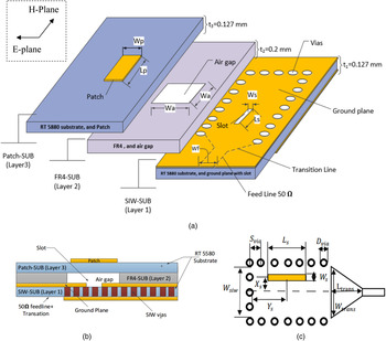
The three-dimensional (3D) view of aperture-coupled membrane antenna is shown in Fig. 1(a). The proposed structure consists of three dielectric layers, SIW-SUB, FR4-SUB, and Patch-SUB, respectively. The layer 1 (SIW-SUB) made of low-loss/cost material RT Duroid 5880 permittivity ε r = 2.23, tangent loss tanδ = 0.004 [Reference Vettikalladi, Lafond and Himdi27] with a thickness of, t 1 = 0.127 mm. This substrate has a top and bottom metal layer of thickness 18 µm, where the SIW vias is integrated on the same substrate as shown in Fig. 1(b). The microstrip line and the transition to SIW are developed on the lower side of layer 1 while a slot is etched on the top side of the same substrate. The SIW parameters are shown in Fig. 1(c), which are calculated from the guidelines given in [Reference Kumar, Jadhav and Ranade19, Reference Yan, Hong, Wu and Cui31].
Membrane antenna model: (a) 3D exploded view of model; (b) side view; and (c) 2D view of SIW design.

The SIW equivalent rectangular waveguide whose width “W SIW ” can support the mode “TE 10”, which is determined by the equation (1) at a cut-off frequency for f c = 75 GHz for this design [Reference Yan, Hong, Wu and Cui31].
 $${f_c}(T{E_{10}}) = \displaystyle{c \over {2{W_{SIW}}\sqrt {{\varepsilon _r}}}}, $$
where “c” is the speed of light in free space, “ε r ” is relative permittivity of the material used for layer 1, and “W SIW ” is the width of the SIW; which is the inner separation between two sidewalls created by via holes. “D via ” is the diameter and “S via ” is the center-to center distance between two consecutive via holes. The vias diameter shown in Fig. 1(c) and the via separations are chosen properly to minimize the RF power leakage and to avoid any band-gap phenomenon within the operating frequency band of 77–81 GHz. A 50 Ω microstrip feeding is connected to SIW through a microstrip – SIW transition having length “L trans ” and width “W trans ” [Reference Kumar, Jadhav and Ranade19].
Just above the layer 1, layer 2 (FR4-SUB) is placed with thickness of, t 2 = 0.2 mm, and permittivity ε r = 4.4. The air gap is made by drilling the FR4 substrate with an optimized dimension of W a = 3 × 3 mm2 = 0.79λ 0 × 0.79λ 0. We used the FR4 substrate because it is very cheap and easily available in the market. FR4 substrate is only a support not affecting the performance of the antenna. The radiating element of a single MPA is located on the top of layer 3 (Patch-SUB), which is supported by layer 2, having the same characteristic of layer 1. The Patch shown in Fig. 1(a) is excited by longitudinal slot located on the ground plane of layer 1, having a width “W s ” and length “L s ”, with displacement from the centerline of “X s ”. This slot length “L s ” is approximately half of the effective wavelength “λ eff ”, which can be calculated from [Reference Henry, Free, Izqueirdo, Batchelor and Young32]:
 $${L_s} = \displaystyle{{{\lambda _{eff}}} \over 2} = \displaystyle{{{\lambda _0}} \over {\sqrt {2({\varepsilon _r} + 1)}}}, $$
where “λ 0” is the free space wavelength and “ε r ” is the permittivity of the dielectric.
The coupling distance “Y s” from the short circuit of SIW to the center of the slot is as shown in Fig. 1(c), which is at distance of λ g /4 or an odd multiple of it. From simulation, the optimized distance-matching antenna impedance is taken to be Y s = 4.1 mm ≈ 7 λ g /4 for considering the manufacturing easiness. The full-wave electromagnetic (EM) modeling solver of CST Microwave Studio (MWS) is used to design the antenna parameters. Extensive simulation work has been done using CST to find the optimum slot, air gap, and patch dimensions to combine their resonance frequencies for wide BW operation. The optimized antenna parameters are listed in Table 1.
Design parameters.

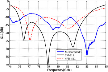
Figure 2 shows the comparison of reflection coefficient (S 11) between the simulated and measured results of the base membrane antenna. The simulated impedance BW of the proposed antenna is in between 75.97 and 82.96 GHz (i.e. 8.85%) by using CST and a little less in HFSS simulation results. The slight difference between the simulated results of CST and HFSS is due to the different numerical techniques employed by the two softwares. Both the results cover the desired frequency BW of 77–81 GHz. There is a shift of frequency band in measured results compared with simulation results which may be due to the manufacturing tolerance and also the effect of W-band connector. We did not take into account the effect of W-band connector during the simulation.
Comparison between simulated and measured results of S 11 versus frequency for the membrane antenna.

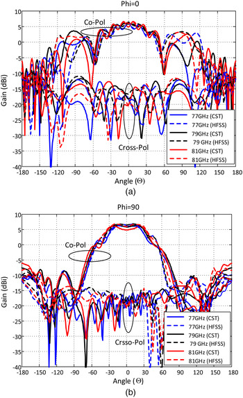
The simulated radiation patterns of the proposed antenna in both E and H planes using CST and HFSS simulators are shown in Figs 3(a) and 3(b), respectively. It can be seen that a good agreement is achieved between the CST and HFSS simulation results for the frequencies at 77, 79 and 81 GHz. The co-polar and cross-polar levels can be seen in each plane. The half power beam width is 63.2° for the E-plane and 69.4° for the H-plane at 79 GHz. The ripple in the E-plane pattern is due to the limited ground plane. The front to back radiation level difference is more than 12 dB in both planes. There is a cross-polar level of less than −24 dB at all frequencies in both planes. The maximum simulated gain is found to be 6.29 dBi, whereas the directivity is 7.82 dBi at a frequency of 79 GHz with 70% radiation efficiency.
Radiations pattern of the membrane antenna for different frequencies at 77, 79, and 81 GHz (a) E-plane, (b) H-plane.

B) Membrane antenna with superstrate layer
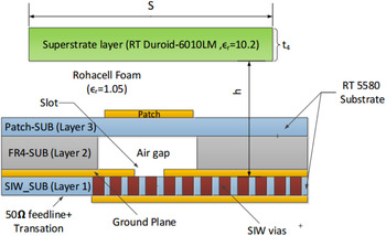
A superstrate dielectric layer of Roger substrate RT-duroid 6010-LM with thickness of, t 4 = 0.254 mm, permittivity ε r = 10.2, and tangent loss tanδ = 0.0023 is added above the base membrane antenna explained in Section “II (A)” is shown in Fig. 4. All parameters for the base antenna are the same as explained in the previous section. A superstrate layer (layer 4) is loaded above the membrane antenna at a height of h = 0.5λ 0. A Rohacell foam layer of permittivity 1.05 is sandwiched between the base membrane antenna and superstrate layer as support. The thickness of the superstrate (t 4), dimension of the superstrate (S), and the height of the superstrate from the ground plane (h) are studied as explained below. The dimensions of substrates and ground are taken as 25 × 25 mm2 for the manufacturing point of view.
Cutting plane view of the membrane antenna with a superstrate layer. Ground plane size is 25 × 25 mm2.

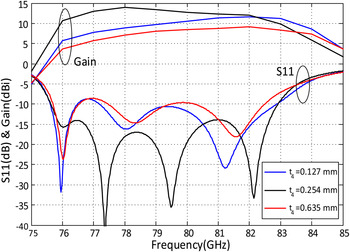
The variation of S 11 and gain versus frequency with different RT-duroid 6010-LM superstrate thickness t 4 = 0.127, 0.254, and 0.635 mm for a fixed height of h = 0.5λ 0, and a fixed superstrate size of S = 6.58 λ 0 × 6.58 λ 0 ≈ 25 × 25 mm2 are shown in Fig. 5. It is noted that the maximum gain obtained is 13.98 dBi for an available superstrate thickness of t 4 = 0.254 mm at a desired frequency BW of 77–81 GHz. This thickness is nearly equal to theoretical one (λ g /4 = 0.297 mm).
Variation of S 11 and gain versus frequency with various superstrate thickness for a fixed height of h = 0.5λ 0, and a fixed superstrate size of S = 6.58λ 0 × 6.58λ 0.

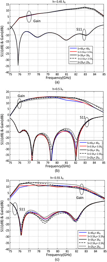
Figures 6(a)–6(c) show the variation of return loss (S 11) and gain versus frequency for various superstrate dimension of S = 4λ 0 × 4λ 0, 3.5λ 0 × 3.5λ 0, 3λ 0 × 3 λ 0, 2.5λ 0 × 2.5 λ 0, and 2λ 0 × 2λ 0 for different heights of 0.45, 0.5, and 0.55λ 0, respectively. It is clear from Fig. 6(b) that the maximum gain with good BW is achieved for a superstrate height of h = 1.895 mm, which is equal to the theoretical height of h = 0.5λ 0with a superstrate dimension of, S = 3λ 0 × 3λ 0, and is found to be 15.4 dB at 79 GHz. In all other cases, either the gain is less than or the VSWR BW is worse.
Variation of S 11 and gain versus frequency with various superstrate dimensions for different height “h” from the ground plane. (a) h = 0.45λ 0, (b) h = 0.5λ 0, and (c) h = 0.55λ 0.

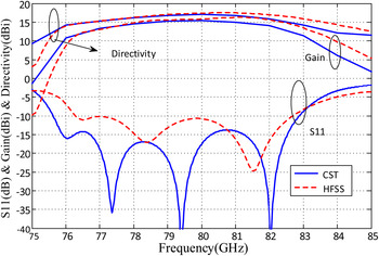
The CST and HFSS results of the return loss (S 11), gain, and directivity for the optimized dimensions are given in Fig. 7. The 2:1 VSWR BW using CST is noted to be BW = 75.6–82.9 GHz (i.e. 9.24% impedance BW) with a maximum gain of 15.4 dBi, and directivity of 17 dBi at 79 GHz. The radiation efficiency estimated to be 69.2%.The results are in a good agreement between the two simulators. There is a gain enhancement of 9.11 dB with the loaded superstrate layer as compared with without superstrate. The results are verified using HFSS and are in good agreement.
Results of S 11, gain, and directivity versus frequency of the superstrate antenna for an optimized superstrate dimension of S = 3λ 0 × 3λ 0, and a height of h = 0.5λ 0.

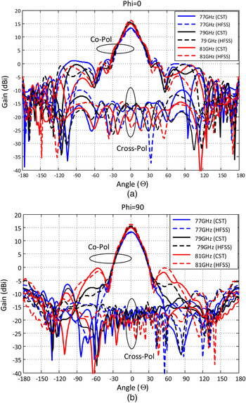
The E-plane and H-plane radiation characteristics by using CST and HFSS simulators for different frequencies of 77, 79, and 81 GHz are shown in Figs 8(a) and 8(b), respectively. Both the simulation results are in good agreement. The co-polar and cross-polar levels can be seen in each plane. Thus, E-plane has a side lobe level (SLL) of −15.3 dB, with a 3 dB beamwidth of 22.3° at 79 GHz. The H-plane has a SLL of −21.8 dB, with a half power beamwidth of 22.5°. The broesight to back radiation level is more than 21 dB in both the planes. All the radiation patterns are found to be good within the BW of interest in both the planes. The cross-polar level is lower than −30 dB at all frequencies within the band in both planes.
Simulated (a) E-plane and (b) H-plane radiation patterns of a superstrate antenna for an optimized superstrate dimension of S = 3λ 0 × 3λ 0, and a height of h = 0.5λ 0.

C) Membrane antenna with FSS on superstrate layer
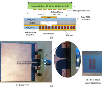
The side view of aperture-coupled membrane antenna with FSS on the bottom surface of a superstrate layer is shown in Fig. 9(a). Figure 9(b) (i) shows the back side of the prototype of FSS superstrate antenna with W-band connector and Fig. 9(b) (ii) shows the FSS on the bottom of the superstrate. The different layers of the prototype are glued by using 3 M glue with a thickness of 40 µm. The glue between SIW-SUB and FR4-SUB are cut with the same dimension as FR4 gap in order to avoid the blockage of radiation from the slot.
FSS superstrate antenna: (a) side view. (b) FSS layer and back view of the prototype, showing microstrip to SIW transition. The 2 × 7 unit cells FSS layer is shown on the bottom side of the optimum superstrate size of S = 3λ 0 × 3λ 0.

Once the FSS is used on superstrate layer, there is coupling between the radiating element (patch) and the FSS layer that affects the performance of the antenna in terms of S 11, gain, and efficiency. The EM waves which are radiated from the base antenna impinge on the FSS layer which forces the distribution of EM waves in space and control the phase. The patches of FSS get excited and multiple reflections happen inside the cavity and finally the wave leakage to outside the cavity from the FSS superstrate and this coherent wave leakage make the antenna structure become high gain. This in turn affects the performance of antenna.
The reflection coefficient phase of the whole structure in Fig. 9(a) is 2πN as explained in equation (3), which is calculated by using simple well-known ray-tracing formula [Reference Feresidis and Vardaxoglou29, Reference Foroozesh and Shafai30]
 $${\varphi _{FSS}}({f_0}) + {\varphi _g}({f_0}) - 2\beta h = 2\pi N,\quad N = 1,2, \ldots, $$
where “N” is an integer number, “φ FSS ” and “φ g ” are the reflection phases of the FSS and the ground plane, respectively, “β” is the propagation constant, and “h” is the distance between the ground plane and the FSS layer. The resonance condition takes place at the boresight angle (θ = 0°) and the operating frequency f 0 can be obtained from the following equation [Reference Foroozesh and Shafai33]
 $$h = \displaystyle{{N{\lambda _0}} \over 2} + [{\varphi _{FSS}}({f_0}) + {\varphi _g}({f_0})] \times \displaystyle{{{\lambda_0}} \over {4\pi}}. $$
From the above analysis it is clear that for a highly reflective surface used as FSS, with a reflection phase close to – π, and reflection phase of PEC ground plane is close to π, provided the height “h” of FSS layer from the ground plane is approximately λ 0/2.
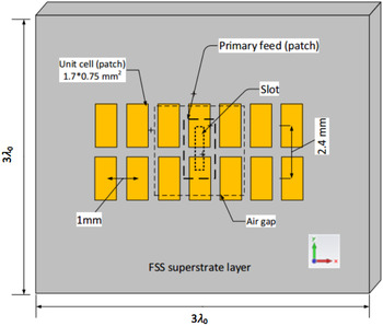
The 2D bottom view of the FSS on superstrate layer (optimized superstrate size in Section “II (B)”) is depicted in Fig. 10. The optimized unit cell size of a single FSS patch is found to be 1.7 × 0.75 mm2 by using CST solver simulator with the distance from the center to center of unit cells as 2.4 mm along Y-axis and 1 mm along X-axis as shown in Fig. 10.
2D bottom view of FSS on a superstrate layer.

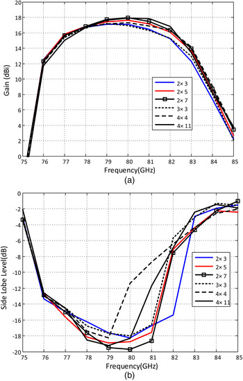
The variations of gain over frequency, and SLL over frequency, for different array of unit cells are explained in Figs 11(a) and 11(b), respectively. It is noted that maximum antenna gain and the best SLL over the frequency band of interest are found to be at an FSS array size of 2 × 7 unit cells. The maximum gain obtained is 17.9 dBi at 79 GHz. It is also noted that the complete coverage of patches (4 × 11 unit cells) on superstrate increases the SLL in the frequency band of interest, even though the gain is almost the same as 2 × 7 array unit cells.
(a) Gain, and (b) SLL versus frequency of the antenna with varying the dimensions of the unit cells array.

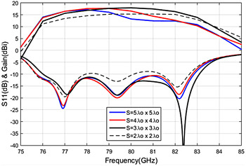
In order to verify that the addition of FSS on the bottom surface of the optimized superstrate as explained in Section “II (B)” gives the best results, we studied the effect of various superstrate sizes of “S = 5λ 0 × 5 λ 0, 4λ 0 × 4 λ 0, 3λ 0 × 3 λ 0, and 2λ 0 × 2 λ 0” with FSS, on antenna performance as shown in Fig. 12. It is found that the optimized superstrate size for the maximum gain is still 3λ 0 × 3 λ 0 as compared with other cases.
Variation of S 11 and gain versus frequency for different superstrate sizes (S) with FSS on the bottom surface of the superstrate layer.

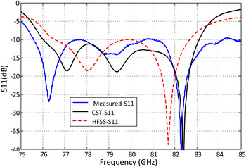
Figure 13 shows the comparison of reflection coefficient (S11) between simulated and measured results of the optimized 2 × 7 unit cells FSS superstrate antenna. It is clear from the figure that there is a good agreement between the simulated (HFSS and CST) and measured results. The measurement was done using Agilent Network Analyzer N5251A with a W-band connector. Calibration is done using standard open-short-load method. The connector loss is obtained from the S 11 measurement of the connector alone which is found to be 0.75 dB (1.5 dB for two ways). The measured results show an impedance BW of 75.57–84.18 GHz (10.89%), whereas the simulated CST MWS results show impedance BW of 76–83.1 GHz (8.98%). Both results cover the frequency band of interest.
Comparison between simulated and measured results of S 11 versus frequency of the antenna with an FSS layer of 2 × 7 unit cells.

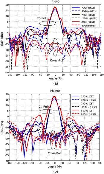
The E-plane and H-plane radiation pattern at frequencies 77, 79, and 81 GHz are shown in Figs 14(a) and 14(b), respectively. It is noted from the E-plane radiation pattern that at 79 GHz, a SLL of −19.8 dB with a half-power beamwidth of 16.9° and a back radiation of −28.2 dB are observed. The H-plane radiation pattern at 79 GHz has a SLL of −23.8 dB, half-power beamwidth of 17°, back radiation of −28.2 dB are obtained. A cross-polarization level of less than − 32 dB is achieved in both planes. It is noted there is a widening of main beam at 81 GHz in both planes, it maybe because of the presence of FSS on the bottom of the superstrate layer. It can be seen that a good agreement is achieved between the CST and HFSS simulations for the frequencies at 77, 79, and 81 GHz. The maximum gain achieved is 17.9 dBi at 79 GHz. The radiation efficiency is estimated to be 65%.
Simulated (a) E-plane and (b) H-plane radiation patterns of the antenna with an FSS layer of 2 × 7 unit cells.

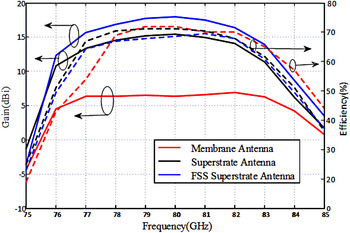
Figure 15 shows the comparison of gain, and efficiency versus frequency for the membrane antenna, superstrate antenna, and FSS superstrate antenna. It is noted that, the maximum gain of a single antenna with FSS layer is 17.9 dBi, which is higher than 2.5 over its superstrate antenna, and higher than 11.61 dB over its basic membrane antenna at 79 GHz. The estimated radiation efficiencies for membrane antenna, superstrate antenna, and FSS superstrate antenna are 70, 69.2, and 65%, respectively, at 79 GHz.
Comparison of the gain, and efficiency versus frequency between the base antenna, superstrate antenna, and the FSS superstrate antenna.

III. CONCLUSION
This paper has demonstrated a high gain aperture-coupled membrane antenna with FSS on superstrate layer for 79 GHz SRR automotive systems. The base antenna shows an impedance BW of 8.85% from 75.97 to 82.96 GHz with a gain of 6.29 dBi at 79 GHz. Adding the superstrate layer increases the gain to 15.4 dBi at 79 GHz. The FSS on superstrate antenna again increases the gain up to 17.9 dBi with an impedance BW of 76 to 83.1 GHz (i.e. 8.98%). The efficiency of the antenna is estimated to be 65% at 79 GHz. Due to the limitation of the measurement facilities, the measured results of the prototype were provided for the input matching (S 11) only. The simulated results for the antenna gain and radiation patterns were provided with the use of CST Microwave studio and were validated by using HFSS software. The measured 2:1 VSWR BW of the total antenna with FSS superstrate layer is from 75.57 to 84.18 GHz (10.89%), which is in agreement with the simulated results.
ACKNOWLEDGEMENT
The authors would like to thank King Abdulaziz City for Science and Technology (KACST) for providing fund through the Project no. ARP 34–137.
 Basem Aqlan received his B.Sc. degree in Electronics and Telecommunication Engineering from the University of Damascus, Syria, in 2010. He has been working at King Saud University, Saudi Arabia, since 2011, where he is currently working toward the M.Sc. degree in Telecommunication Engineering. His main research interests are design and optimization in of millimeter wave antennas, superstrate structures and frequency selective surface.
 Hamsakutty Vettikalladi is an Assistant Professor in the Department of Electrical Engineering, King Saud University since November 2012. He started his carrier as a Postdoctoral researcher at the Bell Engineering Department, University of Arkansas, USA in January 2008, just after finishing his Ph.D. from Cochin University of Science and Technology. Later, he moved Institute of Electronics and Telecommunication of Rennes, University of Rennes1, France. His main research focus includes microwave and millimeter wave antenna design for various applications including high speed WIFI, automotive radar, imaging, point to point communication for 4G/5G. He worked with many projects from various companies such as CANON-France, Bouygues Telecom-France, VALEO Germany, and Thales aerospace in France. He has served as visiting faculty in several institutes, as an editor and referees in several scientific journals and conferences. He is the author of more than 60 research publications in well reputed international journals and conferences and one book chapter.
 Majeed A.S. Alkanhal is a full professor in the Department of Electrical Engineering at King Saud University, Riyadh, Saudi Arabia. He received his Ph.D. in Electrical Engineering from Syracuse University, Syracuse, New York in 1994. His research interests include wireless communications, radar systems, electromagnetic propagation and scattering in complex materials, microwave/millimeter wave antenna design and optimization, modern optimization techniques, and computational electromagnetics. Professor Alkanhal served as consultant, visiting scholar, editor, and referee in several institutes and scientific journals. He has published books, book chapters, research papers, technical re-ports, and patents in his field of research interests.