INTRODUCTION
Lead cut-outs are used frequently in kilovoltage therapy for modifying the size or shape of the field from an applicator. However Aldrich et al. Reference Aldrich, Meng and Andrew1 have shown that high surface doses can occur when uncoated lead cut-outs are placed directly in contact with the patient's skin. Much of the surface dose comes from secondary electrons, which are electrons released through photoelectric absorption or Compton scattering of X-rays incident on matter.
In Compton scattering, an X-ray photon transfers some of its energy to an electron in the medium, and is deflected from its original path. This electron can receive a large fraction of the original X-ray energy.
With photoelectric absorption, the X-ray photon is absorbed and a photoelectron is ejected from one of the electron shells in the atom. The vacancy in the electron shell is filled quickly by another electron, with either a characteristic (secondary) photon or an Auger electron being emitted.
At kilovoltage energies in a higher atomic number element such as lead, photoelectric absorption is predominant, with the creation of energetic photoelectrons. The mechanism by which the dose to the skin from lead cut-outs is increased is predominantly the production of photoelectrons. Nevertheless, the concept of surface dose requires definition, as the surface of interest is actually beneath the epidermis. WhittonReference Whitton2 measured the mean ± standard deviation epidermal thickness as 6.6 ± 2.0 mg/cm2, 5.5 ± 2.4 mg/cm2 and 4.7 ± 1.4 mg/cm2 on the arms and legs, head and trunk respectively. The ICRP has subsequently recommended3 that skin surface dose should be evaluated at the depth of the basal cell layer, which varies between 20 μm and 100 μm over the whole body.
With the basal cell layer, as defined by the ICRP, being within the range of photoelectrons generated in lead shielding,Reference Klevenhagen, D'Souza and Bonnefoux4 it is essential that these photoelectrons are removed before they strike the skin in order to avoid a dose that makes no contribution to the therapeutic effect. Fortunately lead cut-outs are usually coated to prevent the toxic lead from polluting the environment or the skin of patients and radiographers. This also has the effect of removing many of the contaminating photoelectrons. These coatings may be based on paint or tape.
MATERIALS AND METHODS
Although a tape such as masking tape can prevent electron contamination, it does not present a surface that is easy to clean or to maintain in a hygienic state. Gloss paint is sometimes used as the coating, and this has the advantage of being easy to clean, but it also has a tendency to chip and crack, particularly when the lead cut-out is bent to follow the shape of the patient. In response to these problems, the authors of this article have formulated a new coating based on a 50% emulsion paint and 50% Copydex (Henkel, Winsford, Cheshire, England) mixture.
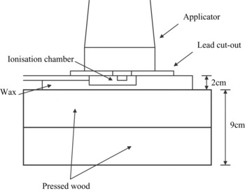
To test the efficacy of the new coating for removing photoelectrons, the apparatus shown in Figure 1 was assembled. The performance of a 0.12 mm thickness of the new coating was compared against that of a 0.3 mm thickness of masking tape and a 0.12 mm thickness of gloss paint. There was also an investigation of the impact of increasing the thickness of the new coating to 0.25 mm.
The apparatus for the measurements.

Measurements were taken using a thin window parallel plate chamber. The chamber employed was the NE2532/3 (Nuclear Enterprises, Reading, England) with a volume of 0.03 cm3 and a thin 0.03 mm entrance window made of polyethylene (CH2).
The kilovoltage unit employed was a DXT-300 (Pantak, Reading, England) with two modalities 135 kVp (7.15 mm Al HVT) and 225 kVp (1.65 mm Cu HVT) being used.Reference Aukett, Thomas, Seaby and Gittins5 Two applicators were attached to the treatment head in turn; a 4 cm diameter, 30 cm FSD open-ended applicator and a 10 cm diameter, 50 cm FSD closed applicator with a 4 mm thick plastic end-cap. The Pantak applicators use apertures to define the beam, so the walls of the applicator do not contribute to the collimation of the beam. The photoelectron contamination of the photon beam from the applicator is therefore very low.
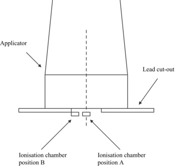
Holes of 2 cm diameter were cut in 2 mm thick sheets of lead. The centre of the aperture of the cut-out was placed on the central axis of the applicator. Measurements were taken with the centre of the chamber at the centre of the cut-out aperture (position A), and at the edge of the cut-out aperture (position B) as shown in Figure 2.
The positioning of the ionisation chamber.

RESULTS
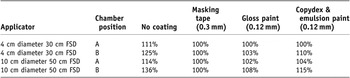
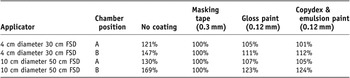
Photoelectron contamination from the lead cut-out was more pronounced with higher energy photons, and increased the ionisation chamber reading for uncoated cut-outs by up to 69% at position B relative to the reading obtained with a 0.3 mm coating of masking tape (Table 2). The new coating was not quite as effective as the gloss paint in reducing the surface dose for the 135 kVp modality (Table 1). However the new coating appears to be as effective, if not superior to, the gloss paint in reducing the surface dose for the 225 kVp modality (Table 2). A 0.12 mm thickness of coating appears to be adequate for absorbing the photoelectrons, as increasing the thickness did not have a significant effect on the surface dose. Doubling the thickness of the new coating to 0.25 mm only led to a 1–2% point change in the ionisation readings relative to those obtained from the 0.12 mm thickness.
Relative ionisation measured using the ionisation chamber with various coatings on the cut-out for 135 kVp, 7.15 mm Al HVT

Relative ionisation measured using the ionisation chamber with various coatings on the cut-out for 225 kVp, 1.65 mm Cu HVT

The main advantage of the new coating was its elasticity. Bending of the cut-outs, as would be the case when treating a curved surface, resulted in cracking of the gloss paint coating, whereas the new pliable coating based on Copydex and emulsion paint suffered no damage. Furthermore, in comparison with masking tape, the new coating is easier to clean.
CONCLUSIONS
The new coating has proved itself to be very satisfactory in clinical use. It reduces the secondary electron dose satisfactorily, and furthermore it isolates the toxic lead from staff, patients and the environment. Rough handling, particularly strikes with sharp objects, can damage the coating and result in some peeling. However in normal use the coating is very resilient, even when the cut-out is bent. A thickness of 0.12 mm was found to be adequate for removing contaminating electrons from the beam at kilovoltage energies. This corresponds to three coats of the coating applied with ∼30 minutes of drying time between each coat.