Introduction
Global navigation satellite systems (GNSS) are widely used nowadays for many applications. Taking advantage of several different systems allows a more accurate navigation solution (in particular because of a larger number of visible satellites) and allows offering a partial resistance to RF interferences, whether intentional or unintentional (jamming, multipaths, harmonics of some oscillators, etc.) [Reference Gleason and Gebre-Egziabher1, Reference Poisel2].
We propose here two compact circularly polarized (CP) antennas embedded in a metallic cavity for integration on high-speed carriers enduring accelerations and shocks. The applications targeted here require the use of metallic cavities to ensure strong and reliable mechanical resistance of the overall antenna systems. As the use of small-size cavities (<0.4λ 0 typically, where λ 0 is the wavelength at the central frequency) significantly degrades the antenna performance, innovative solutions must be found to circumvent these drawbacks.
In this context, it has been demonstrated previously that the use of metasurfaces allows enlarging the bandwidth (BW) of antennas embedded in such small cavities [Reference Martinis, Mahdjoubi, Sauleau, Collardey and Bernard3, Reference Martinis, Bernard, Mahdjoubi, Sauleau and Collardey4]. More precisely, several GNSS metasurface-inspired antennas in cavities have been studied both in linear [Reference García-Gámez, Sauleau, Collardey, Bernard, Mahdjoubi, Pouliguen and Potier5] and circular [Reference Garcia-Gamez, Sauleau, Collardey, Bernard, Mahdjoubi, Pouliguen and Potier6] polarization. Similar geometries are also well detailed in the open literature under the acronym ARMA but with larger structures, typically of 0.5λ 0; in [Reference Karmann, Martinod, Andrieu, Majed and Rammal7], a small ARMA element was reduced to 0.31λ. In [Reference Garcia-Gamez, Sauleau, Collardey, Bernard, Mahdjoubi, Pouliguen and Potier6], operation in CP has been achieved using four feed points and sequential rotation; this antenna system (whose size is the same as the one selected here, namely 50 × 50 × 20 mm3), exhibits an excellent axial ratio (AR) over a frequency band covering the L1 (GPS), E1 (Galileo); B1 (Beidoo), and G1 (Glonass) GNSS bands, i.e. from 1559 to 1610 MHz. In spite of covering the whole upper GNSS band, this design suffers from mutual coupling between opposite input ports, thus degrading the antenna radiation efficiency.
We propose in the section “Structure with four feed points and a partial intermediate ground plane for upper and lower band coverage” an alternative evolution of the structure [Reference Garcia-Gamez, Sauleau, Collardey, Bernard, Mahdjoubi, Pouliguen and Potier6], which is able to cover entirely the lower and upper GNSS bands ([1164;1300] MHz and [1559;1610] MHz). To reach a dual-band response with this antenna, an additional partial ground plane is added in the middle of the cavity. To reach the frequency band objective, the cavity is larger than in [Reference Garcia-Gamez, Sauleau, Collardey, Bernard, Mahdjoubi, Pouliguen and Potier6], being 60 × 60 × 20 mm3.
We introduce in the section “Structure with two feed points for upper band coverage” a further evolution of the design proposed in [Reference Garcia-Gamez, Sauleau, Collardey, Bernard, Mahdjoubi, Pouliguen and Potier6] by considering only two feed points. We show that this approach leads to a much lower mutual coupling between both input ports with improved radiation performance. Here the selected cavity side is only 0.26λ 0 (50 mm), and the central frequency of operation is 1575 MHz (λ 0 = 190.5 mm).
Numerical and experimental results are given and discussed for both the next sections. Conclusions are drawn in the section “Conclusion”. This paper is an extension of our paper [Reference García-Gámez, Bernard, Sauleau, Collardey, Mahdjoubi, Pouliguen and Potier8].
Structure with four feed points and a partial intermediate ground plane for upper and lower band coverage
Antenna geometry
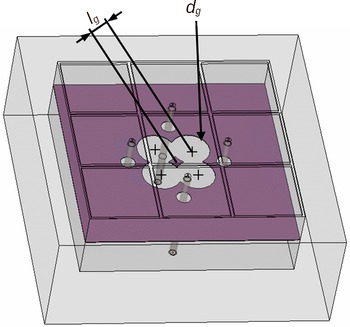
The structure is inspired from the one presented in [Reference Garcia-Gamez, Sauleau, Collardey, Bernard, Mahdjoubi, Pouliguen and Potier6], and the antenna geometry is represented in Fig. 1. It consists of a metallic cavity of inner dimensions 60 × 60 × 20 mm3 (0.23λ 1 × 0.23λ 1 × 0.08λ 1 at the frequency of f 1 = 1164 MHz). This cavity is filled with three dielectric materials, as can be seen in Fig. 10(c): the lower substrate is constituted of Rogers RO3010 (ε r3 = 10.2, tan δ 3 = 0.0027, and h 3 = 11.0 mm), the center one is made of polypropylene (PP) (ε r1 = 2.25, tan δ 1 = 0.001, and thickness h 1 = 7.08 mm [Reference de Cos and Las-Heras9]), and the upper one is a stack of three layers of Rogers RO3010 (ε r2 = 10.2, tan δ 2 = 0.0027, and h 2 = 1.92 mm); each individual layer of Rogers material has a thickness of 0.64 mm. Two arrays made of 3 × 3 sub-wavelength square patches (Fig. 1(a)) are printed on the upper two metallic layers (Fig. 1(c)). Their size and the gap separating two neighboring patches are labeled L and g, respectively. Both arrays are tightly capacitively coupled. On the lower face of this stack, a four-branch star is etched to match the four feedings to 50 Ω, as depicted in Fig. 1(b). The biggest difference with the structure in [Reference Garcia-Gamez, Sauleau, Collardey, Bernard, Mahdjoubi, Pouliguen and Potier6] is the insertion of a 0.6-mm-thick metal plate in the x-y plane at h 3 mm from the bottom of the cavity [Reference García-Gámez10], as can be seen in Fig. 10(c). This metal plate, or said additional partial ground plane, has direct contact with the cavity walls. It has a perforation to allow the non-isolation of one sub-cavity, as illustrated in Fig. 2; it is constituted of four openings of diameter d g whose center is at a distant of l g = 4.8 mm from the cavity center. The four coaxial cables pass through the partial ground plane without being on contact (openings of 2 mm are trimmed in this last one), and their outer conductors are soldered to the star shape (bottom face of the upper dielectric stack-up), whereas their inner conductors are soldered to four of the nine patches on the top face (metasurface top layer). The inner conductors pass though the metasurface layer in the middle of this dielectric substrate, without any contact with their patches (openings of diameter 1.7 mm are trimmed in the four concerned patches). The distance of these feed points to the cavity center is noted as f p. This configuration was retained to be compliant with the mechanical constraints the antenna has to withstand.
(a) The top view of the structure with additional ground plane, (b) feeding shape, and (c) cut view.

A partial ground plane located in the center of the cavity.

It is noted that the cavity is not divided into two equal parts. The position of the plate h 3 on the z-axis allows to match the frequency. If the sheet is closer to the bottom of the cavity, the resonances move toward higher frequencies, as shown in Fig. 3.
A study on the influence of the metal plate position (values in mm) h 3 on the input reflection coefficient.

Furthermore, Fig. 4 represents the input reflection coefficient versus frequency for various opening diameters dg. For smaller values, the four openings are distinct and a wideband behavior is achieved. By still enlarging them, a unique opening is created and two distinct resonances are achieved, which tend to be getting apart with the increase of d g. In combination with the partial ground plane position h 3, this parameter d g is tuned to cover both GNSS bands. The influence of the metasurface parameters g and L are discussed in the section “Structure with two feed points for upper band coverage,” as identical for both structures. The optimized parameters are given in Table 1, and the corresponding simulated S-parameters are represented in Fig. 5 for one port of the prototype. Only one port response is represented since the results are identical for the other three. As expected for small radiating element with multiple ports, the mutual coupling is strong, especially for face-to-face ports [Reference Byun and Choo11, Reference James and Hall12]. Nevertheless, this configuration is well adapted to achieve a very good circular polarization over a wide BW.
The input reflection coefficient versus frequency for various opening diameters d g.

Optimized parameters

Simulated S-parameters of the structure optimized for the GNSS bands.

Experimental results
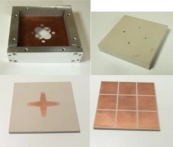
A prototype has been manufactured to validate the design and for the achievement of a dual-band behavior. The main element of the antenna is the metal cavity; the rest of the elements are embedded inside. The particularity of this cavity is the incision that is present in one of its walls. The photograph of the cavity frame is presented in Fig. 6. A slit of height 0.6 mm is used to introduce the metal sheet that separates the cavity into two sub-cavities. A screwed copper plate closes the cavity and allows welding the coaxial probes with the cavity. The intermediate ground plane that divides the cavity is formed by a 0.6-mm-thick copper plate and is inserted in this slit. As Fig. 6 shows, the plate has been milled to extract the circular elements from the center of the sheet. Small circles have also been extracted to introduce the coaxial cables through them. All the elements are carefully introduced into the cavity, making a compact and rigid antenna.
Photographs of the antenna elements.

S-parameters
Measured reflection coefficients for each port of the prototype are presented in Fig. 7. The results show that the expected double resonance is well obtained despite a slight frequency shift with the simulated results. However, the coefficient differs from one port to another and all GNSS bands are not covered, but the principle to achieve two separate matched bands is demonstrated. The measured transmission coefficients are represented in Fig. 8. A down-frequency shift is noted, but the results are in relatively good agreement with the numerical ones.
The measured and simulated reflection coefficients.

The measured transmission coefficients.

Far-fields
A specific feeding circuit summing the incoming signals with a phase quadrature of 90° between the four inputs was designed based on the component SCQ-4-1650 from Mini-circuits. An active version including a low noise amplifier (LNA) was used in [Reference Garcia-Gamez, Sauleau, Collardey, Bernard, Mahdjoubi, Pouliguen and Potier6], as well as for the GNSS reception performances in the subsection “GNSS reception performances”, but a passive version of this circuit is used to perform the radiation measurements presented later. A photograph of the circuit is given in Fig. 9. The measured transmission coefficients in magnitude and phase are given in Fig. 10. The insertion losses (ILs) are estimated between 1.0 and 1.8 dB in the frequency range [1150;1650] MHz, which is in agreement with the component datasheet. The phase quadrature between the inputs is relatively good over this frequency band, with a standard deviation of 1.4° in the worst case.
A schematic view of the feeding circuit and photograph of the circuit.

Measured transmission coefficients of the feeding circuit.

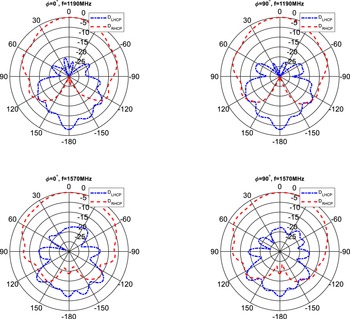
In Fig. 11, radiation patterns for two frequencies (1190 and 1570 Hz) are represented, one in the lower resonance and other one in the upper resonance. The antenna radiation has good agreement with the simulation results. The lower frequency presents a lower cross-polarization than the higher frequencies. In this last case, the degradation of the circular polarization can also be seen.
Measured radiation patterns in two orthogonal cut-planes at 1190 MHz and at 1575 MHz.

Figure 12 represents the AR as a function of frequency. The prototype has a good AR in the entire frequency band. The measured gain versus frequency is shown in Fig. 13. To help compare with numerical results, the measured IL of the feeding circuit are averaged between the four ports and subtracted from the measured gain value for each frequency point. The frequency shift previously observed is also noted in this figure; the low gain values for the lowest frequencies are explained by the small radiating aperture size and the high mutual coupling between the four antenna ports.
The simulated and measured axial ratio.

The simulated and measured gain versus frequency.

GNSS reception performances
This antenna was used with an active circuit (additional low-noise amplifier of 18 dB to the passive circuit mentioned above) to perform some GNSS signal acquisition with a multiband and multi-constellation receiver from Septentrio. The number of satellites used with a carrier-to-noise ratio C/N larger than 30 dB is summarized in Table 2. As can be seen, this antenna is valid for reception of signals from two different constellations (GPS and Galileo tested) and on different frequency bands. It validates its efficiency to be used for navigation.
The number of used satellites during the acquisition (5 minutes)

Structure with two feed points for upper band coverage
Antenna geometry
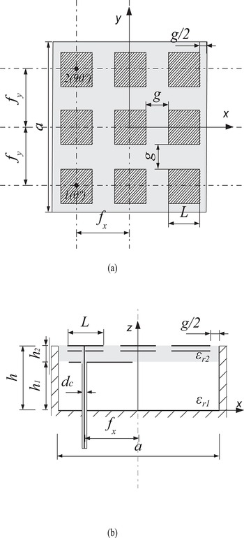
The antenna geometry is represented in Fig. 14. It consists of a metallic cavity of inner dimensions 50 × 50 × 20 mm3 (0.26λ 0 × 0.26λ 0 × 0.11λ 0). This cavity is filled with only two dielectric materials: the lower substrate is PP (h 1 = 18.08 mm) and the upper one is made of Rogers RO3210 (h 2 = 1.92 mm). Two layers of metasurface are etched on this last dielectric material. The upper array is fed by two coaxial probes whose outer conductors are soldered to two orthogonal printed strips, as illustrated in Fig. 15. Both feed points are located at a distance fx and fy from the cavity center. In contrast to [Reference Garcia-Gamez, Sauleau, Collardey, Bernard, Mahdjoubi, Pouliguen and Potier6] and to the previous section, these strips do not intersect, thus resulting in a low coupling between the two ports (see the section “Numerical results and design guidelines”). This configuration allows to reach a greater BW than that offered by a conventional small patch embedded in the same cavity.
The influence of the main design parameters is briefly discussed in the next section.
(a) Top view of the structure and (b) side view of the structure.

Feeding systems of the proposed antenna. Both probes are etched on the lower metallic substrate (Fig. 1b).

Numerical results and design guidelines
As explained in [Reference Garcia-Gamez, Sauleau, Collardey, Bernard, Mahdjoubi, Pouliguen and Potier6], the gap g is a key parameter to tune the antenna resonance frequency as it governs the capacitance of the metasurface at the cavity aperture. Here, to achieve a resonance frequency around 1575 MHz, g is equals to 3 mm. Consequently, L is set to 13.6 mm to keep the metasurface size slightly smaller than the cavity side (50 mm).
The matching level of the antenna can be controlled by optimizing fx, fy and the strips dimensions l and t. The antenna has been designed using HFSS and optimized through exhaustive parametric studies. The optimized dimensions are provided in Table 3. As an example, we only show here the influence of fx and fy on the antenna input impedance (note that we only provide the impedance values at one feed port since the results are identical for the second input port). The corresponding results are given in Fig. 16 for fx and fy, varying between 13.5 and 17.5 mm (the other parameters are identical to the values given in Table 3). This figure shows that increasing the values of fx and fy leads to a higher real part of the input impedance at resonance and in an increase of the resonance frequency.
Optimized parameters

Reflection coefficient for various feed point locations.

After optimization, both ports are matched to 50 Ω around 1575 MHz, with a −10-dB BW of 90 MHz, as can be seen in Fig. 17; the GNSS bands E1, G1, L1, and B1 are all covered. Compared to our previous work in [Reference Garcia-Gamez, Sauleau, Collardey, Bernard, Mahdjoubi, Pouliguen and Potier6], the antenna architecture proposed here is simpler and exhibits a lower mutual coupling between input ports (−17 dB here) and a higher realized gain (Fig. 18), larger than 4.4 dB over the GNSS band (1559–1610) MHz.
Simulated and measured S-parameters.

Simulated and measured realized gain.

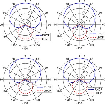
The radiation patterns computed at 1575 MHz are represented in Fig. 19 in four vertical cut-planes. In all cases, we can see that the cross-polarization level remains lower than −20 dB over almost the entire upper hemisphere; the AR is better than 3 dB over the angular range [−79; 84]° in the worst case, denoting a good CP quality. The half-power beamwidth is around 112° in all cut-planes.
Simulated radiation patterns at 1575 MHz in 4 cut-planes φ = 0°, 45°, 90°, and 135° (φ defined from x axis in xy plane).

The simulated AR is represented against frequency in Fig. 20. It remains lower than 2 dB over the whole matched band.
Simulated and measured realized axial ratio (AR).

Experimental results
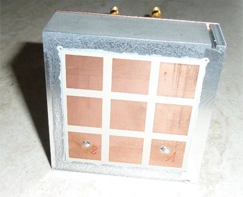
The antenna studied in the previous section has been manufactured. It is shown in Fig. 21 where both feed points can be easily seen.
Photograph of the manufactured prototype.

S-parameters
The measured S-parameters are plotted in Fig. 17. The achieved −10 dB BW equals 65 MHz (1535 to 1600 MHz) and covers the GNSS L1, B1, and E1 bands ([1559; 1591] MHz). The measured coupling between the ports is lower than −20 dB, over these three bands. These results are in a relatively good agreement with the simulated ones, despite the slight frequency shift of the port 1 response.
Far-fields
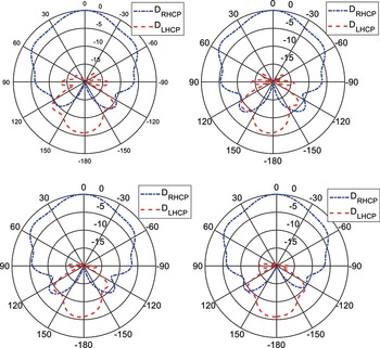
The measured gain is represented in Fig. 18; it reaches 3.2 dB and is higher than 2.7 dB over the GNSS bands E1, L1, and B1. The discrepancy with the numerical values is partly attributed to the losses in the combiner used during the measurement (Mini-Circuits ZAPDQ-2-S, with typical ILs around 0.8–0.9 dB in the considered frequency range). The measured AR is provided in Fig. 19. It remains lower than 2 dB over the band of interest. Nevertheless, a discrepancy between simulation and measurement is noted out of the GNSS band, around 1.5 dB; it could be attributed to the matching difference between port 1 and port 2 in experiment. Finally, the measured radiation patterns are given in Fig. 22. These measurements confirm the very low cross-polarization level in the upper hemisphere.
Measured radiation patterns at 1575 MHz in 4 cut-planes φ = 0°, 45°, 90°, and 135° (φ defined from x axis in xy plane).

GNSS reception performances
This antenna has been used as passive antenna to receive GNSS signals in the upper band; the results are summarized in Table 4, denoting a good capacity to receive such signals.
Number of used satellites during the acquisition (5 minutes)

Conclusion
We proposed here two CP metasurface-inspired cavity antennas of small sizes for GNSS applications in harsh environments: 0.23λ 1 × 0.23λ 1 × 0.08λ 1 at the frequency of 1164 MHz and 0.26λ 0 × 0.26λ 0 × 0.11λ 0 at the frequency of 1575 MHz. The first one proposed an innovative solution to create a dual-band behavior of such structures with four ports by the insertion of a partial ground plane in the middle of the cavity. The principle is validated by a prototype. A good AR is achieved over all the GNSS bands. The second antenna is fed with only two coaxial probes and presents good radiation performance (AR < 2 dB, gain of 3.2 dB, low cross-polarization in the upper hemisphere). The measured BW is of 65 MHz, and this antenna covers GNSS bands L1, B1 and E1 (experimental results); numerical results also cover in addition the G1 band. The results presented here demonstrate improved performance with a much lower mutual coupling between input ports compared to [Reference Garcia-Gamez, Sauleau, Collardey, Bernard, Mahdjoubi, Pouliguen and Potier6].
For these two prototypes, discrepancies were noted with numerical results but also between the ports themselves. They could be attributed to many causes in a nonindustrial manufacturing process, but before all they reveal the great sensitivity of these structures to asymmetries and manufacturing tolerances. Further steps would be required to achieve a product manufacturing process. Nevertheless, from a development point of view, the results obtained demonstrate the validity of both concepts for the realization of small-size broadband cavity antennas.
Funding Statement
This work was funded in part by the French-German Research Institute of Saint-Louis and in part by the Direction Générale de l’Armement, French Ministry of Armed Forces.
Competing interest
The authors report no conflict of interest.

Laura García Gámez received the Dipl.Ing. degree in telecommunications engineering from the University of Granada, Granada, Spain, in 2015 and the Ph.D. degree in electronics from the University of Rennes 1, Rennes, France, in 2020. After receiving her Ph.D., Laura has held postdoctoral research studies on antenna arrays at the University of Limoges, Limoges, France. In 2022, she joined Indra Sistemas, Madrid, Spain, as a senior engineer, where she is involved in the design of the TR modules for airborne radars. She is the author of several conference and journal papers on compact cavity antennas.

Loïc Bernard graduated in Electronics and Communication Systems from the National Institute of Applied Sciences (INSA) of Rennes, France, in 2000. After this engineer degree, he received the PhD degree in electrical engineering from INSA of Rennes, France, in 2003. He joined the French-German Research Institute of Saint-Louis (ISL), France, in May 2004 as a research scientist. He received the “Habilitation à Diriger des Recherches” degree from the University of Rennes 1, Rennes, France, in 2017. In 2021, he also became an associate member of the Institute of Electronic Telecommunication of Rennes (IETR). He is involved in the electronics instrumentation of flying systems with very high dynamics for aerodynamic and ballistic researches; his research interests focus on antennas and antenna arrays, microwave circuits, and metamaterials.

Ronan Sauleau got his postgraduate degree and M.Sc. in electrical engineering and radio communications from the Institut National des Sciences Appliquées, Rennes, France, in 1995. He received the Agrégation degree from the Ecole Normale Supérieure de Cachan, France, in 1996 and the Doctoral degree in signal processing and telecommunications and the “Habilitation à Diriger des Recherches” degree, both from the University of Rennes 1, France, in 1999 and 2005, respectively. He was an assistant professor and associate professor at the University of Rennes 1 between September 2000 and November 2005 and between December 2005 and October 2009, respectively. He has been appointed as a full Professor in the same University since November 2009. His current research fields are numerical modeling, millimeter-wave beam steering antennas, substrate integrated waveguide antennas, lens-based focusing devices, periodic and non-periodic structures (FSS, metasurfaces, polarizers, reflectarrays, and transmitarrays), and biological effects of millimeter waves. He has been involved in more than 70 research projects at the national and European levels and has co-supervised 27 postdoctoral fellows, 57 PhD students, and 50 master students. He has received 20 patents and is the author or coauthor of more than 280 journal papers and 580 publications in international conferences and workshops. He was co-director of the research Department “Antenna and Microwave Devices” at IETR and deputy director of IETR between 2012 and 2016. He is now the director of IETR. Prof. Sauleau received the 2004 ISAP Conference Young Researcher Scientist Fellowship (Japan) and the first Young Researcher Prize in Brittany, France, in 2001 for his research work on gain-enhanced Fabry-Perot antennas. In September 2007, he was elevated to Junior member of the “Institut Universitaire de France”. He was awarded the Bronze medal by CNRS in 2008 and the silver medal in 2020. He received the 2021 Antenna EurAAP Award. He was the co-recipient of several international conference awards with some of his students (Int. Sch. of BioEM 2005, BEMS’2006, MRRS’2008, E-MRS’2011, BEMS’2011, IMS’2012, Antem’2012, BioEM’2015, EuCAP’2019, EuCAP’2021, and EuMW’2022). He served as a guest editor for the IEEE Antennas Propogat. Special Issue on “Antennas and Propagation at mm and sub-mm waves”. He served as a national delegate for several EU COST actions. He has served as a national delegate for EurAAP and as a member of the board of Director of EurAAP from 2013 to 2018.

Sylvain Collardey received his PhD degree in telecommunication from the University of Rennes 1, France, in 2002. He was graduated in Electronics and Telecommunication Engineering at the University of Rennes 1 in the year 1998. Currently, he is associate professor at the University of Rennes 1 and involved as researcher in the Antennas and Microwaves group at the Institute of Electronic Telecommunication of Rennes (IETR). Specialist in antennas, his interest areas are the characterization and development of small antennas, EBG materials and metamaterials, and RFID. He has published more than hundred revue papers and conference communications.

Kourosh Mahdjoubi received the M.E.E. degree from the Engineering School of Tehran University, Teheran, Iran, the Master’s degree from the École Nationale Supérieure d’Électronique et de Radioélectricité de Grenoble, INPG, Grenoble, France, and the Doctor–Engineer Diploma and the HDR Diploma degrees from the University of Rennes 1, Rennes, France. He is currently a Professor with the University of Rennes 1, where he is with the Antenna Department of the IETR Laboratories, Institute of Electronics and Telecommunications of Rennes. He is also a Visiting Professor with the Ecole Polytechnique, University of Nantes (Polytech’Nantes), Nantes, France. He has been a former Board Member of the European School of Antennas, Rennes, and an organizer of the course on microwave and millimeter-wave antennas. He has been involved in body-centric antennas and electromagnetic modeling for antenna applications, including the FDTD method, moments method, spectral domain approach, mode matching techniques, modal expansion, and cavity method. He has authored about 20 review and communication papers. His current research interests include metamaterial and EBG antennas, characterization methods for bianisotropic materials, miniature antennas, receiving antennas, and orbital angular momentum of electromagnetic waves.

Philippe Pouliguen received the M.S. degree in signal processing and telecommunications, the Doctoral degree in electronic and the “Habilitation à Diriger des Recherches” degree from the University of Rennes 1, France, in 1986, 1990, and 2000. In 1990, he joined the Direction Générale de l’Armement (DGA) at the Centre d’Electronique de l’Armement (CELAR), now DGA Information Superiority (DGA/IS), in Bruz, France, where he was a “DGA senior expert” in electromagnetic radiation and radar signatures. He was also in charge of the EMC (Expertise and ElectoMagnetism Computation) laboratory of DGA/IS. From 2009 to 2018, Dr. Pouliguen was the head of “acoustic and radio-electric waves” scientific domain at DGA, Paris, France. Since 2018, he is the Innovation Manager of the “acoustic and radio-electric waves” domain at the Agence Innovation Défense (AID). His research interests include electromagnetic scattering and diffraction, Radar Cross Section (RCS) measurement and modeling, asymptotic high frequency methods, radar signal processing and analysis, antenna scattering problems, and Electronic Band Gap Materials.

Patrick Potier received the Ph.D. degree in structure and property of the material from the University of Rennes, Rennes, France, in 1984. From September 1984 to September 1987, he was an Engineer of research in Thomson CSF, Paris, France. Since September 1987, he has been an Engineer of the Center “Maîtrise de l’information” (Information Superiority), “Direction Générale de l’Armement” (General Armaments Directorate, the French Procurement Agency), Bruz, France. He treats the aspect antennas and radiation and ensures the follow-up of various studies and theses.