I. INTRODUCTION
Carbon nanotubes (CNTs) have recently been used in the field of composite materials due to the extraordinary mechanical, thermal, and electrical properties of CNTs. Based on tensile test of single-wall CNTs (SWCNTs), Yu et al. Reference Yu, Files, Arepalli and Ruoff1 found that SWCNTs have a Young's modulus of ∼1 TPa and tensile strength of ∼30 GPa. Treacy et al. Reference Treacy, Ebbesen and Gibson2 suggested that the tensile strength of multiwall CNTs (MWCNTs) is ∼150 GPa, which are much higher than that of SWCNTs.
Researches focusing on the fabrication of polymer matrix composites and ceramic matrix composites have been undertaken to obtain the desired properties. Reference Tjong3–Reference Wang, Padture and Tanaka6 On the other hand, for the metal matrix composites (MMCs), the progress has been rather slow. Zeng et al. Reference Zeng, Zhou, Xu, Xiong, Luo and Wu7 suggested that one of the remaining challenges to manufacture CNT-based metal composites is to obtain a homogeneous dispersion of CNTs in the matrix. CNTs can easily agglomerate due to the large differences in surface tension and mass density between CNTs and metal matrix. Reference Lau and Hui8
Various fabrication methods, such as friction stir processing, Reference Lim, Shibayanagi and Gerlich9,Reference Liu, Ke, Liu, Huang and Xing10 infiltration method, Reference Kim, Babu and Kang11 semisolid powder processing, Reference Wu and Kim12,Reference Wu, Kim and Russell13 powder metallurgy Reference Esawi and Morsi14–Reference Dominique, Raynald and Robin16 and stir-casting process, Reference Kang, Jun, Jong, Hyoen, Yong, Dong, Dong, Hye, Chandan, Chan and Young17,Reference Oh, Lim, Kim, Yoon, Kim, Lee, Sung and Han18 have been developed to incorporate CNTs into the aluminum (Al) matrix. Traditionally, powder metallurgy is the favorable method for fabricating metal matrix nanocomposites. However, powder metallurgy is not suitable for large scale production due to its longer processing cycle and higher cost than that of stir-casting process. On the contrary, stir-casting process offers a simple and cheap alterative way to fabricate large scale composites which can be used as billets to manufacture a great variety of products through other processes. Nevertheless, only a few researchers adopted stir-casting process mainly because of the following issues: (i) CNTs are lighter than all commercial metals, and not wetted by alloy melts; (ii) easily agglomerate owing to the Van der Waals interaction.
In this study, an original two-step process, which combines the merits of powder metallurgy and casting, was presented to fabricate the CNTs/A356 nanocomposites. CNTs and Al powders were used to produce Al–CNT master nanocomposites with a large concentration of CNTs. Then the prepared master nanocomposites were added into A356 alloy to fabricate CNTs/A356 nanocomposites with lower CNT contents. The Al–CNT master nanocomposites were used as a dispersing agent to pre-disperse CNTs. The microstructure and mechanical properties of CNTs/A356 nanocomposites were investigated subsequently.
II. EXPERIMENTAL PROCEDURES
A. Master nanocomposites manufacturing
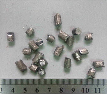
In this study, MWCNTs (Sun nanoteck Co., 96% purity, 40–70 nm in diameter and 1–10 µm in length) and pure Al powders (Damao Inc., ∼20 µm particle size) were used to fabricate Al–8 wt% CNT master nanocomposites. Al powders containing 8 wt% CNTs were produced by ball milling. The milling was performed in a planetary ball milling machine, partly filled by ceramic balls at a constant rotation speed of 180 rpm for 5 h. The ball to powder weight ratio was 10:1. To fabricate the Al–CNT master nanocomposites, the mixed powders which were wrapped in aluminum foil were hot extruded at 390 °C with an extrusion ratio of 40:1. The extruded master nanocomposites were then cut into small pieces of 3–6 mm length, as shown in Fig. 1.
Photographs of the Al–CNT master nanocomposites.

B. Fabrication of CNTs/A356 nanocomposite
Commercial A356 aluminum alloy was used as the base alloy in this investigation, with chemical composition presented in Table I. A356 alloy was melt in a clay-graphite crucible by using an electric resistance furnace. Then the alloys were heated up to 750 °C and carefully skimmed to remove the impurities. Al–8 wt% CNT master nanocomposites were inserted one by one and they were submerged beneath the melt surface. After complete melting of the master nanocomposites, the liquid melt was stirred at a speed of 300 rpm for 10 min under N2 atmosphere. The mass content of CNTs in the CNTs/A356 nanocomposites was controlled by the feeding amount of master nanocomposites. The surface of the melt was skimmed and the melts were then poured into the permanent mold at 700 °C. For the purpose of comparison, A356 base alloy without CNTs was also subjected to the same fabrication process as mentioned before.
Chemical compositions of A356 aluminum alloy.

C. Materials characterization
Microstructural examination was performed by optical microscope (Nikon ECLIPSE MA200, Nikon Corporation, Tokyo, Japan) and scanning electron microscope (SEM; NOVA NANOSEM 450, FEI Company, Hillsboro, Oregon). X-ray diffraction (XRD) and differential thermal analysis (DTA) were conducted to analyze the interfacial reaction of the CNTs in Al matrix. The contact angles were measured by a sessile drop test, which was described in detail by Landry et al. Reference Landry, Kalogeropoulou and Eustathopoulos19 The hardness of samples was measured by a micro Vickers hardness (HVS 1000A, Jinan, Shangdong, China). For statistical confidence, 10 indentations were conducted to obtain an average microhardness of each sample. The tensile test was conducted on universal testing machine to investigate the strengthening effect of different CNT concentrations. Subsequently, the acquired fracture surfaces were examined by SEM.
III. RESULTS AND DISCUSSION
A. The chemical stability and wettability of CNTs in Al matrix
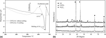
To study the chemical stability of CNTs in Al matrix, DTA curves of the initial and milled Al–8 wt% CNT powders are given in Fig. 2(a). First of all, it can be seen that there were two thermal events during the heating of the initial un-milled Al–8 wt% CNT powders. The first event observed is an endothermic peak ranging from 635 to 665 °C, which is associated with the melting of Al. The other exothermic event just after the melting of Al is associated with the exothermic Al4C3 formation, as it was identified by Zhang et al. Reference Zhang, Deng, Wang, Geng and Geng20 As for the DTA curve of the milled Al–8 wt% CNT powders in Fig. 2(a), it is very interesting to note that the exothermic event occurs before Al melting. Figure 2(b) shows the XRD patterns of the milled Al–8 wt% CNT powders. For the patterns of the milled Al–8 wt% CNT powders, only Al peaks can be found and there are no CNT peaks. The absence of CNT peak may be attributed to uniform dispersion of CNTs. The outer surface of CNTs were all wrapped by Al. Furthermore, no characteristic peak corresponding to the formation of aluminum carbide is observed. However, CNT peaks appeared when the milled powders were annealed at 635 and 750 °C for 2 h in vacuum. As shown in Fig. 2(b), XRD patterns of the annealed Al–8 wt% CNT powders further verify that Al4C3 carbides were formed by reaction of Al–CNTs. And this explains why CNT peaks appear again after annealing. On the other hand, the presence of CNT peak indicates that not all CNTs can be transformed into Al4C3 even when they are annealed at 750 °C for 2 h.
(a) DTA curves of the initial and milled Al–8 wt% CNT powders; (b) XRD patterns of milled Al–8 wt% CNT powders (1) followed by annealing at 635 °C (2) and 750 °C (3) for 2 h.

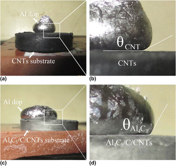
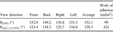
To completely transform Al into Al4C3, mixtures of CNTs, carbon black and Al powders, whose atomic ratio is 3:3:4, were annealed at 1100 °C for 1 h in a vacuum induction furnace. There might be some carbon black and remained CNTs after annealing treatment. So the remaining mixtures can be expressed as Al4C3/C/CNTs. Figure 3 shows the optical images after sessile drop, in which the contact angles between Al drop and pristine CNTs [Fig. 3(a)], and Al4C3/C/CNTs [Fig. 3(c)] substrates can be clearly seen. To improve reliability, several different views were used to characterize the contact angle, as summarized in Table II. Srinivasa et al.
Reference Srinivasa, Anup, Virendra, Sudipta and Arvind21
suggested that the contact angle strongly depended on the temperature, the substrate surface roughness and the atmosphere. As listed in Table II, in the case of wetting of Al on pristine CNT substrate, the average contact angle of θCNTs was 152°. However, the average contact angle of
 ${\theta _{{\rm{A}}{{\rm{l}}_4}{{\rm{C}}_3}/{\rm{C}}/{\rm{CNTs}}}}$
was reduced to 120° due to the formation of the carbide (Al4C3). As a result, it is expected that the formation of Al4C3 as interfacial reaction product contributes to the wetting and the infiltration of liquid aluminum melt into CNT clusters. The work of adhesion between the liquid and the substrate is defined as Young-Dupre' equation, as given below:
 $${w_{\rm{A}}} = {\gamma _{{\rm{LV}}}}\left( {1 + \cos \,\theta } \right)\quad ,$$
where θ is the contact angle and γLV ≈ 850 mJ/m2 is the liquid–vapor surface energy. The adhesion works of raw Al–CNTs and Al–Al4C3/C/CNTs were calculated as 99 and 421 mJ/m2, respectively. Hence, strong interfacial bonding is expected by the formation of interfacial carbide (Al4C3), resulting in the improvement of load transfer from matrix to CNTs.
Optical images after sessile drop of aluminum at 800 °C in vacuum. Contact angle measurement of Al on (a), (b) pristine CNT substrate and (c), (d) Al4C3/C/CNT substrate.

Contact angles measured from different views after sessile drop of aluminum at 800 °C.
B. Microstructures of the CNTs/A356 nanocomposites
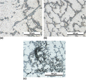
The microstructures of the as-cast A356 alloys with and without addition of Al–8CNT master nanocomposite are given in Fig. 4. Figure 4(a) shows typical coarse plate-like eutectic silicons distributed along the boundaries of the α-Al. And the segregation of silicon is observed. It can be clearly seen from Fig. 4(b) that the eutectic silicons in the 0.2 wt% CNTs/A356 nanocomposite were refined by the addition of CNTs. However, some microvoids are found in Fig. 4(c) when 0.4 wt% CNTs were added. This is owing to the fact that superfluous quantity of CNTs impedes the dispersion process, resulting in agglomeration of CNTs along the boundaries of α-Al [Fig. 4(c)].
Optical micrographs of the pure A356 alloys (a) and CNTs/A356 nanocomposites with addition of 0.2 wt% CNTs (b) and 0.4 wt% CNTs (c).

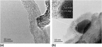
Figure 5 shows the transmission electron microscopy (TEM) images of the as-cast 0.4 wt% CNT reinforced nanocomposite. As shown in Fig. 5(a), a typical tubular multiwall nanotube structure is clearly visible, and there are some disorder areas on the surface of the tube. Structural changes of the CNTs can be observed. The wall layers were reduced due to the formation of Al4C3 as discussed above. However, CNT of a diameter of ∼40 nm with clean surface can be obviously seen in Fig. 5(b). And there are no other reactants between CNT and Al matrix. Al4C3 particle with a size of ∼15 nm was detected at the tip surface of a CNT, which is much smaller than the Al4C3 found by Liu et al. Reference Liu, Xu, Xiao, Xue, Wang and Ma15 The inset in Fig. 5(b) is the high-magnification image of the interface between carbide and CNT, showing aluminum carbide with lattice fringes of the (0 1 5) plane. Wu et al. Reference Wu, Kim and Russell13 reported the improvement of tensile properties of pure Al by CNT incorporation. In their process, Al4C3 could be scarcely formed at the interface, which indicates that the interface without any materials can also provide interfacial strength enough to transfer tensile loading. Thereby, the clean interface between Al matrix and CNTs can also strengthen the composites.
(a) Representative TEM image of the as-cast 0.4 wt% CNT reinforced A356 nanocomposite and (b) high-magnification image of the interface between carbide and CNT.

C. Analysis of mechanical properties
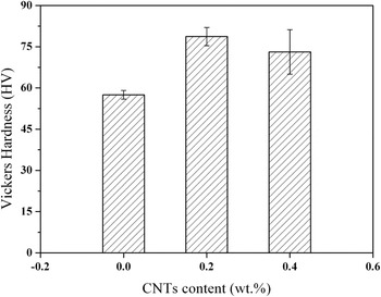
Figure 6 shows the influence of CNT addition on the microhardness of A356 alloys. It was measured by using a hardness tester with applying a load of 500 gf. It can be clearly seen that the microhardness value of the nanocomposites with small amount of CNTs. Several factors may lead to the hardness improvement of the CNTs/A356 nanocomposites. Normally, due to the difference in the thermal expansion coefficient between the reinforcements (CNTs) and the matrix, a large number of dislocations were developed in MMCs. Another factor may be the formation of Al4C3 which possesses higher hardness and melting points. However, further increasing CNT addition to 0.4 wt% led to the reduction in hardness. This can be attributed to the agglomeration of CNTs within the matrix metal. Agglomeration of CNTs promotes plastic flow and induces the formation of microvoids in the matrix metal, finally giving rise to the lower Vickers hardness value.
The microhardness of CNTs/A356 nanocomposites.

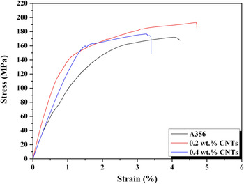
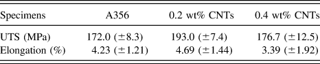
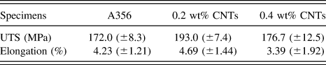
The tensile stress–strain curves of CNTs/A356 nanocomposites are presented in Fig. 7. Their mechanical properties are summarized in Table III. It can be seen from Fig. 7 that the pure A356 alloy and CNT reinforced nanocomposites show a brittle type of curves. The elongation of 0.2 wt% CNTs/A356 nanocomposite was almost equal to that of the pure A356 alloy. Meanwhile, compared to the matrix alloy (172.0 MPa), the ultimate tensile strength (193 MPa) of the 0.2 wt% CNTs/A356 nanocomposite was increased by 12.2%. It can be attributed to the change in the morphology of eutectic silicon particles and α-Al phases, and the dispersion strengthening effect of CNTs in the matrix. However, with superfluous addition of 0.4 wt% CNTs, the microvoids and CNTs agglomerations could be found in the composites, as shown in Fig. 4(c). The microcracks would form around the conglomerations and microvoids when the 1.5 wt% CNTs/A356 nanocomposite was subjected to applied loads, leading to the deterioration in the mechanical properties.
Tensile stress–strain curves of CNTs/A356 nanocomposites.

Ultimate tensile strengths (UTSs) and elongations of CNTs/A356 nanocomposites.
D. Fracture surface morphology of CNTs/A356 nanocomposites
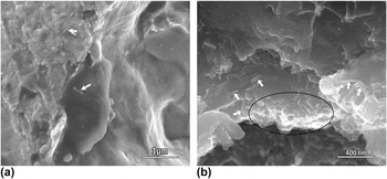
Figure 8 shows the SEM images of the tensile fractographs of the CNTs/A356 nanocomposites. The fracture surface of the 0.2 wt% CNTs/A356 nanocomposite is given in Fig. 8(a), in which CNTs are uniformly distributed and their directions are random. However, some naked CNTs stand on the fracture surface of 0.4 wt% CNTs/A356 nanocomposite in Fig. 8(c), which indicates that the interface bonding force between CNTs and the matrix is very weak, and that the load transfer from the matrix to CNTs is not adequately utilized. Moreover, there are some conglomerations (marked in the black circle) of CNTs in the 0.4 wt% CNTs/A356 nanocomposite as shown in Fig. 8(c).
SEM images of the tensile fractographs of CNTs/A356 nanocomposite reinforced with (a) 0.2 wt% CNTs; (b) 0.4 wt% CNTs.

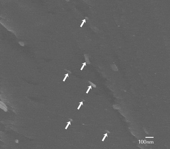
Figure 9 shows the tensile fractographs of the extruded 0.2 wt% CNTs/A356 nanocomposite. As shown in Fig. 9, CNTs are aligned in the same direction as that of applied tensile stress. Meanwhile, some CNTs are pulled out on the tension fracture surfaces of the nanocomposites and the tips observed on the fracture surface is very short, suggesting a very strong interfacial bonding between CNTs and the matrix.
SEM image of tensile fractograph of extruded 0.2 wt% CNTs/A356 nanocomposite.

IV. CONCLUSIONS
CNT reinforced nanocomposites were fabricated by adding the diluted Al–8 wt% CNT master nanocomposite. XRD and DTA results revealed that CNTs were not stable and that aluminum carbide (Al4C3) would be formed before the melting of Al when the composite powders of CNTs and Al were milled. Formation of Al4C3 was proved to improve wettability of CNTs in Al melt, which is critical for improving mechanical properties of CNTs/A356 nanocomposites. Microstructures of A356 alloy were refined by CNT addition. When the addition amount of CNTs was less than 0.4 wt%, the CNTs could be homogenously distributed in the matrix by stir-casting process. The findings indicated that the addition of CNTs enhanced the mechanical properties of the CNTs/A356 nanocomposites. Fractography analysis revealed that CNTs were distributed uniformly throughout the fracture surface. The master nanocomposite approach to produce high performance metallic composites has great potential in industrial applications.
ACKNOWLEDGMENTS
This research is supported by the National Natural Science Foundation of China (Nos. 51364035), Ministry of Education Tied up with the Special Research Fund for the Doctoral Program for Higher School (20133601110001), Loading Program of Science and Technology of College of Jiangxi Province (KJLD14003)., Production and Teaching and Research Cooperation plan of Nanchang Non-party Experts and Doctor (2012-CYH-DW-XCL-002).