1. Introduction
Capsules, small liquid drops enclosed by elastic membranes, are widely used for encapsulation, transport and release of active agents in applications such as cosmetics and drug delivery. They are also widely employed as model systems of biological cells. Capsules are often suspended in flowing fluids, for instance, cells in blood flows and artificial capsules in microfluidic flows. In this case, viscous stresses acting on the membranes, caused by the external flow, may lead to large deformation of the capsules and affect their functions. Therefore, extensive studies have been devoted to the fluid mechanics of capsules in flowing fluids. It is revealed that the deformation and dynamics of capsules are governed by the viscous forces from the internal and external fluids and the elastic forces within the capsule membrane. The viscous forces and the membrane elastic forces are found to be affected by the mechanical properties of the membrane (Pozrikidis Reference Pozrikidis2001; Lac et al. Reference Lac, Barthes-Biesel, Pelekasis and Tsamopoulos2004; Lac & Barthes-Biesel Reference Lac and Barthes-Biesel2005), the shape of the capsule (Ramanujan & Pozrikidis Reference Ramanujan and Pozrikidis1998; Bagchi & Kalluri Reference Bagchi and Kalluri2009; Walter, Salsac & Barthes-Biesel Reference Walter, Salsac and Barthes-Biesel2011), the shear rate and the type of the external flow (Ramanujan & Pozrikidis Reference Ramanujan and Pozrikidis1998; Lac et al. Reference Lac, Barthes-Biesel, Pelekasis and Tsamopoulos2004; Zhao & Bagchi Reference Zhao and Bagchi2011), the viscosity of the internal fluid (Ramanujan & Pozrikidis Reference Ramanujan and Pozrikidis1998; Foessel et al. Reference Foessel, Walter, Salsac and Barthes-Biesel2011) and the inertia of the external and internal flows (Sui et al. Reference Sui, Chew, Roy and Low2009; Bai et al. Reference Bai, Luo, Wang, He, Lu and Xu2013b ; Luo et al. Reference Luo, Wang, He, Xu and Bai2013b ).
A compound capsule consists of an elastic capsule containing a smaller elastic capsule inside. Such a compound capsule can be taken as a model system of eukaryotic cells or of parasite-infected red blood cells (RBCs) (the inner capsule representing the cell nucleus or the parasite) to study their deformation and dynamics (Veerapaneni et al. Reference Veerapaneni, Young, Vlahovska and Blawzdziewicz2011; Hosseini & Feng Reference Hosseini and Feng2012; Kaoui, Kruger & Harting Reference Kaoui, Kruger and Harting2013; Abreu et al. Reference Abreu, Levant, Steinberg and Seifert2014; Levant & Steinberg Reference Levant and Steinberg2014). The behaviours of compound capsules in flows are much more complex than those of homogeneous capsules, since the viscous forces on the membranes can be significantly affected by the hydrodynamic interaction between the inner and outer membranes. However, the fluid mechanics of compound capsules in flows is largely unexplored, since previous studies have mainly focused on the deformation of homogeneous capsules.
A limited number of previous studies concern the deformation and dynamics of compound capsules. The deformation and breakup of liquid droplets with uniform surface tension are found to be significantly affected by the presence of second droplets inside (Stone & Leal Reference Stone and Leal1990; Smith, Ottino & de la Cruz Reference Smith, Ottino and de la Cruz2004; Qu & Wang Reference Qu and Wang2012; Chen, Liu & Shi Reference Chen, Liu and Shi2013; Wang et al. Reference Wang, Liu, Han and Guan2013), but capsules with elastic membranes present quite different hydrodynamic behaviours due to the distinct mechanics of the capsule membrane and the droplet interface. Hosseini & Feng (Reference Hosseini and Feng2012) found that rigid parasite particles inside RBCs greatly reduced the deformability of RBCs. But they focused their study only on the deformation of parasite-infected RBCs under stretching in quiescent fluids. Recently, experimental observations of compound vesicle dynamics in flowing fluids were reported by Levant & Steinberg (Reference Levant and Steinberg2014) and they indicated that the dynamics of compound vesicles were far richer and more complex than those of homogeneous vesicles. However, only a limited number of cases were demonstrated in their work, owing to the experimental complexities in the fabrication and manipulation of the compound vesicles and the observation of their flow behaviours on the micro-scale. Using theoretical and numerical approaches, Veerapaneni et al. (Reference Veerapaneni, Young, Vlahovska and Blawzdziewicz2011) and Kaoui et al. (Reference Kaoui, Kruger and Harting2013) found that either enclosed rigid particles or enclosed deformable vesicles induced new dynamical features of vesicles owing to the hydrodynamic interaction between the inclusion and the vesicle membrane. However, these studies are limited by using small-deformation theories or two-dimensional (2D) simulations. Previous studies on homogeneous capsules show that the hydrodynamic behaviours of capsules in three dimensions are quite different from those in two dimensions (Salac & Miksis Reference Salac and Miksis2012; Bai et al. Reference Bai, Luo, Wang, He, Lu and Xu2013b ; Luo et al. Reference Luo, Wang, He, Xu and Bai2013b ). Besides, the aforementioned studies on compound capsules have mainly focused on their dynamical behaviours, but the knowledge of their deformation behaviours is the basis for exploring their dynamical behaviours and is also critical for fully understanding their fluid mechanics in flows. Therefore, three-dimensional (3D) systematic studies are needed to investigate the deformation of compound capsules in flows and to reveal the underlying mechanisms.
In this paper, a front tracking–finite element method is derived to systematically investigate the deformation of compound capsules in simple shear flow. A fully 3D finite difference code is developed to solve the governing equations. The numerical method is validated quantitatively by comparing our predictions on the deformation of homogeneous capsules with the results from previous numerical simulations. The effects of the presence of the inner capsule and the corresponding parameters, including the mechanical properties of the inner and outer membranes and the volume fraction of the inner capsule, on the deformation of spherical compound capsules are quantitatively explored. We find that the inner capsule can be deformed to a greater degree than the outer capsule under certain conditions even if the inner membrane has lower capillary number than the outer membrane, which is contrary to our expectation. The mechanisms underlying the mutual effects of the inner and outer capsules on their deformation are discussed.
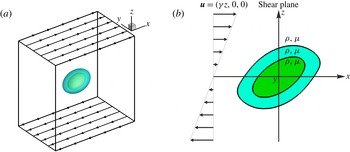
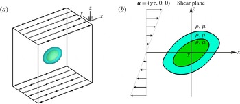
Problem statement. (a) An initially spherical compound capsule is deformed by simple shear flow. (b) The compound capsule consists of an elastic capsule containing a smaller elastic capsule. The inner and outer capsules are concentric, and have the same density and viscosity as the surrounding fluid.
2. Problem description and numerical method
We consider the deformation of a compound capsule suspended in simple shear flow with constant shear rate
 ${\it\gamma}$
(figure 1
a). The compound capsule consists of an elastic capsule (the outer capsule with radius
 $R$
) encapsulating a smaller elastic capsule (the inner capsule). The inner and outer capsules are concentric and initially spherical. The deformation and dynamics of eccentric compound capsules and non-spherical capsules are also of academic interest, but are more involved due to their more complex geometries, and they will be the focus of our future work. Both the inner and outer capsules are bounded by infinite thin elastic membranes with negligible resistance to bending. On account of the research focus of our present work, more complex mechanical properties of the membranes, including membrane bending stiffness and membrane viscosity, will be addressed in our future work, since previous numerical studies show that both membrane bending stiffness and membrane viscosity significantly influence the deformation of homogeneous capsules in shear flow (Pozrikidis Reference Pozrikidis2001; Le Reference Le2010; Yazdani & Bagchi Reference Yazdani and Bagchi2013). The fluids outside the outer capsule, inside the inner capsule and between the inner and outer membranes are taken as incompressible and Newtonian fluids with the same density
 ${\it\rho}$
and viscosity
 ${\it\mu}$
(figure 1
b), unless stated otherwise.
The flows inside and outside the compound capsule are governed by the continuity and Navier–Stokes (NS) equations as follows:
 $$\begin{eqnarray}\displaystyle & \displaystyle \boldsymbol{{\rm\nabla}}\boldsymbol{\cdot }\boldsymbol{u}=0, & \displaystyle\end{eqnarray}$$
 $$\begin{eqnarray}\displaystyle & \displaystyle \frac{\partial ({\it\rho}\boldsymbol{u})}{\partial t}+\boldsymbol{{\rm\nabla}}\boldsymbol{\cdot }({\it\rho}\boldsymbol{u}\boldsymbol{u})=-\boldsymbol{{\rm\nabla}}p+{\it\mu}{\rm\nabla}^{2}\boldsymbol{u}+\boldsymbol{f}, & \displaystyle\end{eqnarray}$$
 $\boldsymbol{u}=(u,v,w)^{\text{T}}$
is fluid velocity,
 $t$
is time,
 $p$
is pressure and
 $\boldsymbol{f}$
is the body force due to the elastic tensions of the inner and outer membranes. A numerical method was developed in our previous works (Bai et al.
Reference Bai, Luo, Wang, He, Lu and Xu2013b
; Luo et al.
Reference Luo, Wang, He, Lu, Xu and Bai2013a
,Reference Luo, Wang, He, Xu and Bai
b
) to simulate the deformation and dynamics of homogeneous capsules in flows. This method is based on the coupling of the front tracking method (for the flow inside and outside the capsule and for tracking the membrane) and the finite element method (for the mechanics of the membrane), which is similar to the methods developed by Li & Sarkar (Reference Li and Sarkar2008) and Yazdani & Bagchi (Reference Yazdani and Bagchi2012). In our present work, we extend this numerical method to the modelling of the deformation of compound capsules. Its procedures are briefly outlined and the technique to track the inner and outer membranes is introduced in the following. More details are available in the referenced studies (Li & Sarkar Reference Li and Sarkar2008; Yazdani & Bagchi Reference Yazdani and Bagchi2012; Bai et al.
Reference Bai, Luo, Lu and Xu2013a
,Reference Bai, Luo, Wang, He, Lu and Xu
b
; Luo et al.
Reference Luo, Wang, He, Lu, Xu and Bai2013a
,Reference Luo, Wang, He, Xu and Bai
b
, Reference Luo, He, Wang, Tasoglu, Xu, Demirci and Bai2014).
In the front tracking method, the multiphase flow system is taken as a single phase with sharp variations of fluid density, viscosity and body force across the membrane. In the present case, body force alone varies across the membrane. The flow fields inside and outside the capsules are obtained on a structured Eulerian grid by solving (2.1) and (2.2). The capsule membrane is tracked by a set of Lagrangian points and is discretized into a set of triangular planar elements by connecting the Lagrangian points. Thus, the membrane can be advected by using the velocity
 $\boldsymbol{u}(\boldsymbol{x}^{\prime })$
of the Lagrangian points, which are interpolated from the velocity
 $\boldsymbol{u}(\boldsymbol{x})$
of adjacent Eulerian grid points as follows:
 $$\begin{eqnarray}\boldsymbol{u}(\boldsymbol{x}_{i}^{\prime })=\mathop{\sum }_{j}D(\boldsymbol{x}_{j}-\boldsymbol{x}_{i}^{\prime })\boldsymbol{u}(\boldsymbol{x}_{j}).\end{eqnarray}$$
Here,
 $i$
and
 $j$
represent Lagrangian and Eulerian points, respectively; and
 $D(\boldsymbol{x}-\boldsymbol{x}^{\prime })$
is the numerical representation of a 3D
 ${\it\delta}$
-function constructed by multiplying three 1D
 ${\it\delta}$
-functions (Unverdi & Tryggvason Reference Unverdi and Tryggvason1992):
 $$\begin{eqnarray}D(x-x^{\prime })=\left\{\begin{array}{@{}ll@{}}\displaystyle \frac{1}{4{\it\Delta}_{e}}\left(1+\cos \left(\frac{{\rm\pi}(x-x^{\prime })}{2{\it\Delta}_{e}}\right)\right)\quad & \text{for}~|x-x^{\prime }|\leqslant 2{\it\Delta}_{e},\\ 0\quad & \text{for}~|x-x^{\prime }|>2{\it\Delta}_{e},\end{array}\right.\end{eqnarray}$$
where
 ${\it\Delta}_{e}$
is the Eulerian grid size.
With the finite element method for the curved elastic membrane in 3D space (Shrivastava & Tang Reference Shrivastava and Tang1993), the membrane strain represented by the strains in the triangular planar elements can be obtained from the advected positions of the Lagrangian points at each time step. The membrane stress can then be computed via constitutive laws. We use the SK constitutive law proposed by Skalak et al. (Reference Skalak, Tozeren, Zarda and Chien1973), in which the strain-energy function is
 $$\begin{eqnarray}W=\frac{G_{s}}{4}[({\it\lambda}_{1}^{4}+{\it\lambda}_{2}^{4}-2{\it\lambda}_{1}^{2}-2{\it\lambda}_{2}^{2}+2)+C({\it\lambda}_{1}^{2}{\it\lambda}_{2}^{2}-1)^{2}].\end{eqnarray}$$
Here,
 ${\it\lambda}_{1}$
and
 ${\it\lambda}_{2}$
are the principal in-plane stretch ratios of the triangular planar elements,
 $G_{s}$
is the shear modulus of the membrane and
 $C$
is the ratio of the area-dilatation modulus to the shear modulus. The principal stresses
 ${\it\tau}_{1}$
and
 ${\it\tau}_{2}$
can be obtained as follows:
 $$\begin{eqnarray}\left.\begin{array}{@{}l@{}}\displaystyle {\it\tau}_{1}=\frac{1}{{\it\lambda}_{2}}\frac{\partial W}{\partial {\it\lambda}_{1}}=\frac{G_{s}}{{\it\lambda}_{1}{\it\lambda}_{2}}[{\it\lambda}_{1}^{2}({\it\lambda}_{1}^{2}-1)+C({\it\lambda}_{1}{\it\lambda}_{2})^{2}({\it\lambda}_{1}^{2}{\it\lambda}_{2}^{2}-1)],\\ \displaystyle {\it\tau}_{2}=\frac{1}{{\it\lambda}_{1}}\frac{\partial W}{\partial {\it\lambda}_{2}}=\frac{G_{s}}{{\it\lambda}_{1}{\it\lambda}_{2}}[{\it\lambda}_{2}^{2}({\it\lambda}_{2}^{2}-1)+C({\it\lambda}_{1}{\it\lambda}_{2})^{2}({\it\lambda}_{1}^{2}{\it\lambda}_{2}^{2}-1)].\end{array}\right\}\end{eqnarray}$$
Other constitutive laws for the membrane mechanics can be implemented into the present method by changing the strain-energy function (i.e. (2.5)). The neo-Hookean (NH) constitutive law is another model widely used for the mechanics of capsule membranes (Ramanujan & Pozrikidis Reference Ramanujan and Pozrikidis1998; Barthes-Biesel, Diaz & Dhenin Reference Barthes-Biesel, Diaz and Dhenin2002; Li & Sarkar Reference Li and Sarkar2008). The strain-energy function is
 $$\begin{eqnarray}W=\frac{G_{s}}{6}\left({\it\lambda}_{1}^{2}+{\it\lambda}_{2}^{2}+\frac{1}{{\it\lambda}_{1}^{2}{\it\lambda}_{2}^{2}}-3\right)\!.\end{eqnarray}$$
The principal stresses
 ${\it\tau}_{1}$
and
 ${\it\tau}_{2}$
are
 $$\begin{eqnarray}\left.\begin{array}{@{}l@{}}\displaystyle {\it\tau}_{1}=\frac{1}{3}\frac{G_{s}}{{\it\lambda}_{1}{\it\lambda}_{2}}\left[{\it\lambda}_{1}^{2}-\frac{1}{{\it\lambda}_{1}^{2}{\it\lambda}_{2}^{2}}\right],\\ \displaystyle {\it\tau}_{2}=\frac{1}{3}\frac{G_{s}}{{\it\lambda}_{1}{\it\lambda}_{2}}\left[{\it\lambda}_{2}^{2}-\frac{1}{{\it\lambda}_{1}^{2}{\it\lambda}_{2}^{2}}\right].\end{array}\right\}\end{eqnarray}$$
The results shown in the following sections correspond to the SK law with
 $C=1$
, unless stated otherwise. The force at each Lagrangian point on the membrane can be calculated from the stresses in the triangular planar elements. Then, the force
 $\boldsymbol{f}(\boldsymbol{x}^{\prime })$
on the Lagrangian points is distributed onto the Eulerian grid points as the body force
 $\boldsymbol{f}(\boldsymbol{x})$
in (2.2) as follows:
 $$\begin{eqnarray}\boldsymbol{f}(\boldsymbol{x}_{j})=\mathop{\sum }_{i}D(\boldsymbol{x}_{j}-\boldsymbol{x}_{i}^{\prime })\boldsymbol{f}(\boldsymbol{x}_{i}^{\prime }).\end{eqnarray}$$
Here, the
 ${\it\delta}$
-function of (2.4) is employed to smooth the force in the membrane from each Lagrangian point onto four adjacent Eulerian points to avoid numerical instability. In the front tracking method, numerical errors in the advection of the interface may induce changes in the total mass of the capsule. In the present method, high-resolution Eulerian and Lagrangian grids can minimize the change to 1–3 %. Nevertheless, in this paper, the volume of the capsule is modified to be its initial value by moving each Lagrangian point along the outward normal direction per time step to ensure mass conservation. The modification in the capsule volume is considerably small (around
 $10^{-7}$
) at each time step, so that its effect on the capsule deformation is negligible. This procedure to ensure mass conservation is also recommended by Tryggvason et al. (Reference Tryggvason, Bunner, Esmaeeli, Juric, Al-Rawahi, Tauber, Han, Nas and Jan2001) for bubble flow simulation.
The governing equations are recast into dimensionless form through scaling lengths by
 $R$
, time by
 ${\it\gamma}^{-1}$
, velocity by
 ${\it\gamma}R$
, pressure and fluid stress by
 ${\it\mu}{\it\gamma}$
, and membrane stress by
 $G_{s}$
. The deformation of the compound capsule is governed by several dimensionless numbers, including the Reynolds number
 $\mathit{Re}={\it\rho}{\it\gamma}R^{2}/{\it\mu}$
(Re is calculated by using the radius of the outer capsule), the capillary number of the outer membrane
 $\mathit{Ca}^{out}={\it\mu}{\it\gamma}R/G_{s}^{out}$
, the ratio of the shear moduli of the outer to the inner membrane
 ${\it\kappa}=G_{s}^{out}/G_{s}^{in}$
and the volume ratio of the inner to the outer capsule
 ${\it\phi}$
. In our simulations, Ca varies from 0.05 to 2.5 to compare our predictions on the deformation of homogeneous capsules with the results from previous numerical reports. Regarding the volume fraction
 ${\it\phi}$
of the inner capsule, nuclei can occupy up to 44 % of the volume in human leukocytes, and parasites can occupy up to 80 % in infected RBCs (Schmid-Schonbein, Shih & Chien Reference Schmid-Schonbein, Shih and Chien1980; Serebrennikova et al.
Reference Serebrennikova, Patel, Milhous and Garcia-Rubio2010; Hosseini & Feng Reference Hosseini and Feng2012). In the present study,
 ${\it\phi}$
varies from 0.05 to 0.25. The present numerical method is able to handle higher values of
 ${\it\phi}$
, whereas higher Eulerian grid resolutions are needed to obtain the flow field in the lubrication gap between the inner and outer membranes, which leads to longer computing time. The present method can be further developed by using adaptively refined Eulerian grids (Agresar et al.
Reference Agresar, Linderman, Tryggvason and Powell1998) to study the deformation of compound capsules with high volume ratios. The deformation of the inner and outer capsules is characterized by two dimensionless parameters: (i) deformation index,
 $D=(L_{1}-L_{2})/(L_{1}+L_{2})$
, where
 $L_{1}$
and
 $L_{2}$
are, respectively, the major and minor axes in the shear plane of the ellipsoid with the same inertia tensor of the deformed capsule; and (ii) orientation angle
 ${\it\theta}$
, the angle between the major axis of the ellipsoid and the
 $X$
-axis (i.e. the flow direction). In the following sections, the superscripts ‘in’ and ‘out’ are used to differentiate the parameters of the inner and outer capsules, respectively, such as
 $\mathit{Ca}^{in}$
,
 $D^{in}$
,
 ${\it\theta}^{in}$
and
 $\mathit{Ca}^{out}$
,
 $D^{out}$
,
 ${\it\theta}^{out}$
, and the superscript ‘
 $H$
’ indicates the parameters of the homogeneous capsule, such as
 $\mathit{Ca}^{H}$
,
 $D^{H}$
,
 ${\it\theta}^{H}$
.
The non-dimensionalized governing equations are solved by a fully 3D finite difference code based on a projection method, in which the NS equation (i.e. (2.2)) is split into a convection–diffusion equation and a pressure Poisson equation. The first step is to solve the convection–diffusion equation to get an intermediate velocity that is not divergence-free. The pressure field is computed by solving the pressure Poisson equation. Velocity is then corrected to be divergence-free in the final pressure-correction step. A three-stage Runge–Kutta technique and the Crank–Nicolson semi-implicit technique are used to update the convective and diffusion terms for stability. In addition, the alternating direction implicit scheme is used for the diffusion term. Spatial derivatives are discretized by using central difference schemes. To accelerate the convergence, the four-level multigrid technique and the alternating direction implicit scheme are used to solve the discretized pressure Poisson equation.
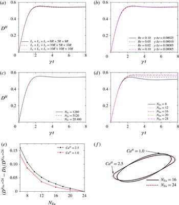
Numerical performance tests by simulating large deformation of a homogeneous capsule (i.e. an elastic membrane with a homogeneous fluid enclosed). (a–d) Effects of computational domain size, Reynolds number and time step size, Lagrangian resolution and Eulerian resolution, respectively, on the deformation of the homogeneous capsule with
 $\mathit{Ca}^{H}=2.5$
. Here
 $N_{Tr}$
is the number of triangular planar elements on the capsule membrane, and
 $N_{Eu}$
is the number of Eulerian grids for one radius of the capsule. (e) Error in
 $D$
at steady state versus
 $N_{Eu}$
. The error is calculated with reference to the equilibrium value of
 $D$
at
 $N_{Eu}=24$
. ( f) Capsule shape at steady state at
 $N_{Eu}=16$
and 24.

3. Numerical performance and validation
To ensure the accuracy of the numerical method, a convergence study is performed to test the effects of computational domain size, time step size, and Eulerian and Lagrangian resolutions on the deformation of homogeneous capsules (figure 2). In previous numerical studies (Doddi & Bagchi Reference Doddi and Bagchi2008; Li & Sarkar Reference Li and Sarkar2008; Luo et al.
Reference Luo, Wang, He, Xu and Bai2013b
), the deformation of capsules with
 $\mathit{Ca}^{H}=0.2$
was employed in the convergence study. The deformation of capsules with higher
 $\mathit{Ca}^{H}$
is larger, thus has higher sensitivity to computational domain size and Eulerian and Lagrangian resolutions. Therefore, in the present convergence test, the deformation of capsules with
 $\mathit{Ca}^{H}=2.5$
is studied, which has the highest deformability among the capsules with
 $\mathit{Ca}^{H}$
ranging from 0.05 to 2.5. The computational domain size of
 $L_{x}\times L_{y}\times L_{z}=10R\times 10R\times 10R$
(
 $x$
,
 $y$
and
 $z$
are the coordinate axes in figure 1) was previously identified to be large enough to eliminate the effects of domain size (Li & Sarkar Reference Li and Sarkar2008; Luo et al.
Reference Luo, Wang, He, Xu and Bai2013b
). Here we find that, as
 $L_{x}\times L_{y}\times L_{z}$
decreases to
 $8R\times 5R\times 8R$
, the equilibrium deformation
 $D^{H}$
increases merely by 0.47 % (figure 2
a), whereas the computing time for one time step decreases by more than 50 %. The effects of time step size
 ${\it\gamma}{\rm\Delta}t$
can be neglected, which is identified by the finding that
 $D^{H}$
decreases only by 0.11 % with
 ${\it\gamma}{\rm\Delta}t$
decreasing from
 $2.5\times 10^{-4}$
to
 $5\times 10^{-5}$
(figure 2
b). Inertia was found in our previous works (Bai et al.
Reference Bai, Luo, Wang, He, Lu and Xu2013b
; Luo et al.
Reference Luo, Wang, He, Xu and Bai2013b
) to significantly affect the deformation and dynamics of capsules when
 $\mathit{Re}>0.1$
. In the present work, we further find that
 $D^{H}$
decreases only by 0.53 % as Re decreases from 0.1 to 0.02 (figure 2
b), whereas time step size has to be decreased by four times to avoid numerical instability. Thus, to explore the effects of the compound structure on the capsule deformation, the following simulations are performed at
 $\mathit{Re}=0.1$
to eliminate the effects of inertia. As
 $N_{Tr}$
(the number of triangular planar elements representing Lagrangian resolution) increases from 5120 to 20 480, the relative variation of
 $D^{H}$
is less than 0.1 % (figure 2
c). Though the computing time increases by around 5 % with
 $N_{Tr}$
increasing from 5120 to 20 480,
 $N_{Tr}=20\,480$
is used to capture the details of sharp tips that may occur at the ends of deformed capsules, especially for capsules with large deformation (Lac et al.
Reference Lac, Barthes-Biesel, Pelekasis and Tsamopoulos2004; Li & Sarkar Reference Li and Sarkar2008; Luo et al.
Reference Luo, Wang, He, Xu and Bai2013b
). The effects of Eulerian resolution on the capsule deformation are presented in figure 2(d–f) with
 $N_{Eu}$
(the number of Eulerian grids for one capsule radius
 $R$
) increasing from 6 to the maximum 24. The capsule deformation increases with increasing Eulerian resolution (figure 2
d). The equilibrium deformation plotted as a function of
 $N_{Eu}$
in figure 2(e) shows the convergence of the present numerical method with increasing Eulerian grid resolution. As
 $N_{Eu}$
increases from 16 to 24, the equilibrium deformation of capsules with
 $\mathit{Ca}^{H}=1$
and 2.5 increases by 1.6 % and 3.0 %, respectively. Besides, no significant changes are observed in the actual capsule shape (figure 2
f) with
 $N_{Eu}$
increasing from 16 to 24, especially for the case of
 $\mathit{Ca}^{H}=1$
.
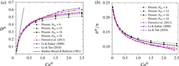
Validation of the present method. The equilibrium (a) deformation
 $D^{H}$
and (b) orientation
 ${\it\theta}^{H}$
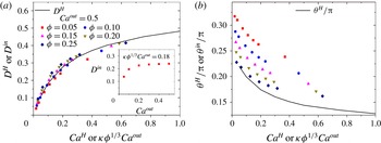
of the homogeneous capsule are compared between our results and those from previous reports. The solid line in panel (a) is the result from the small-deformation theory presented by Barthes-Biesel & Rallison (Reference Barthes-Biesel and Rallison1981).

To validate the present method, quantitative comparisons between our method and those of others, including the small-deformation theory by Barthes-Biesel & Rallison (Reference Barthes-Biesel and Rallison1981), the boundary integral method by Foessel et al. (Reference Foessel, Walter, Salsac and Barthes-Biesel2011), the immersed boundary method by Le & Tan (Reference Le and Tan2010) and the front tracking method by Li & Sarkar (Reference Li and Sarkar2008), are conducted by predicting the deformation
 $D^{H}$
and the orientation
 ${\it\theta}^{H}$
of capsules with
 $\mathit{Ca}^{H}=0.05{-}2.5$
(figure 3). In the validation, the deformation of homogeneous capsules is considered instead of that of compound capsules, as data for the latter are not available, to the best of our knowledge. For capsules with small capillary numbers, e.g.
 $\mathit{Ca}^{H}\leqslant 0.5$
, we can reproduce
 $D^{H}$
and
 ${\it\theta}^{H}$
within 4 % (figure 3
a,b), even if low Eulerian resolution of
 $N_{Eu}=8$
is used. For capsules with higher
 $\mathit{Ca}^{H}$
that approaches 2.5,
 $D^{H}$
predicted with our method is lower than that with the boundary integral method by Foessel et al. (Reference Foessel, Walter, Salsac and Barthes-Biesel2011) (figure 3
a). This finding agrees with Le & Tan’s (the predicted
 $D^{H}$
with their method is lower than that with Foessel et al.’s), but surprisingly our prediction shows an opposite tendency to Li & Sarkar’s (the predicted
 $D^{H}$
with their method is higher than that with Foessel et al.’s). This disagreement is attributable to the difference in the numerical implementation. Notably, the error between our prediction and Foessel et al.’s increases with increasing
 $\mathit{Ca}^{H}$
; for instance, the error is 2.2 % and 7.2 % for
 $\mathit{Ca}^{H}=1$
and 2.5 at
 $N_{Eu}=16$
, respectively. Nevertheless, both
 $D^{H}$
and
 ${\it\theta}^{H}$
are closer to Foessel et al.’s results (figure 3
a,b) in the case of higher Eulerian resolutions. This is because increasing Eulerian resolution can improve the accuracy of the interpolations of velocities and forces between Eulerian and Lagrangian grid points. The error between our prediction and Foessel et al.’s for
 $\mathit{Ca}^{H}=2.5$
can be reduced to 4.3 % by increasing
 $N_{Eu}$
to 24, which indicates that our method can achieve acceptably high accuracy even for high
 $\mathit{Ca}^{H}$
by improving Eulerian grid resolution. In this paper, to ensure a reasonable computational time,
 $N_{Eu}=16$
is used in the following sections, and
 $\mathit{Ca}^{H}$
is restricted to be below 1.
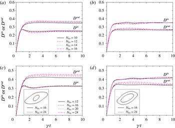
Eulerian resolution tests for simulating the deformation of the compound capsule. Deformation of the inner and outer capsules at (a)
 ${\it\phi}=0.05$
and (b)
 ${\it\phi}=0.25$
when
 $\mathit{Ca}^{out}=0.5$
and
 ${\it\kappa}=1$
; and at (c)
 ${\it\phi}=0.05$
and (d)
 ${\it\phi}=0.25$
when
 $\mathit{Ca}^{out}=1.0$
and
 ${\it\kappa}=1$
. The insets in panels (c) and (d) are capsule shapes at steady state at
 $N_{Eu}=16$
and 24.

Time evolution of the deformation of the homogeneous and compound capsules with (a,b) SK membranes and (c,d) NH membranes. (a,b) The deformation and orientation of the outer capsule when
 $\mathit{Ca}^{out}=0.5$
and
 ${\it\kappa}=1$
. (c,d) The deformation of the outer capsule at
 $\mathit{Ca}^{out}=0.2$
and 0.1 when
 ${\it\kappa}=1$
.

In the front tracking method, finer Eulerian grid resolution is needed for closer interfaces. Thus, compared to the homogeneous capsule, finer Eulerian resolution may be needed for the compound capsule owing to the presence of the inner capsule. The effects of
 $N_{Eu}$
(the number of Eulerian grids for one radius of the outer capsule) on the deformation of the compound capsule are tested with the largest inner capsule (
 ${\it\phi}=0.25$
) or the smallest (
 ${\it\phi}=0.05$
) involved in this study (figure 4), since the inner and outer membranes are closest at
 ${\it\phi}=0.25$
and the radius of the inner capsule is smallest at
 ${\it\phi}=0.05$
. When
 $\mathit{Ca}^{out}=0.5$
and
 ${\it\kappa}=1$
, as
 $N_{Eu}$
increases from 12 to 16, the relative variations of
 $D^{out}$
and
 $D^{in}$
are only 2.9 % and 3.3 %, respectively, for
 ${\it\phi}=0.05$
, and are only 1.2 % and
 ${<}1\,\%$
, respectively, for
 ${\it\phi}=0.25$
. In figure 4(c,d), the convergence study of the Eulerian resolution is presented for the case of the compound capsule with
 $\mathit{Ca}^{out}=1.0$
, the highest capillary number in this study, since the higher capillary number goes for the higher Eulerian resolution as shown in figure 3. The deformation of the compound capsule for
 ${\it\phi}=0.05$
and 0.25 slightly increases with the Eulerian resolution increasing to the maximum 24. As
 $N_{Eu}$
increases from 16 to 24, the relative variations of
 $D^{out}$
and
 $D^{in}$
are only 3.8 % and
 ${<}1\,\%$
, respectively, for
 ${\it\phi}=0.05$
, and are only 2.7 % and
 ${<}1\,\%$
, respectively, for
 ${\it\phi}=0.25$
. Besides, when
 $N_{Eu}$
increases from 16 to 24, no significant changes are observed in the actual shape of both the inner and outer capsules for the two cases of
 ${\it\phi}=0.05$
and 0.25. To ensure a reasonable computational time, the Eulerian resolution of
 $N_{Eu}=16$
is used in the following simulations of the compound capsule deformation.
(a) Deformation and (b) orientation as functions of the capillary number of the outer membrane for the homogeneous capsule and the compound capsule at
 ${\it\phi}=0.05$
and
 ${\it\kappa}=1$
. Several steady shapes are included. The arrowed lines in panel (b) show the major axes of the deformed shapes in the shear plane.

4. Deformation of inner and outer capsules
With the above validated 3D numerical method, we simulate the deformation of a capsule with a smaller capsule inside (i.e. a compound capsule) and without a smaller capsule inside (i.e. a homogeneous capsule). The time evolutions of the deformation
 $D^{out}$
and the orientation
 ${\it\theta}^{out}$
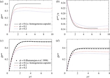
are presented in figure 5. Similar to homogeneous capsules, initially spherical compound capsules deform continuously and eventually assume a steady shape, whereas the presence of the inner capsule induces a decrease in
 $D^{out}$
(figure 5
a). As shown in figure 5(c,d), the same qualitative tendency of
 $D^{out}$
is observed for capsules with membranes conforming to the NH law (Lac et al.
Reference Lac, Barthes-Biesel, Pelekasis and Tsamopoulos2004; Li & Sarkar Reference Li and Sarkar2008). The accuracy of the present method for the NH membrane is validated by reproducing
 $D^{H}$
from Ramanujan & Pozrikidis (Reference Ramanujan and Pozrikidis1998) within 3 % for homogeneous capsules with NH membranes at
 $\mathit{Ca}^{H}=0.1$
and 0.2. In figure 5(b), the equilibrium orientation of homogeneous capsules is higher than that of compound capsules with smaller inner capsules (i.e.
 ${\it\phi}=0.1$
), whereas it is lower than that of compound capsules with larger inner capsules (i.e.
 ${\it\phi}=0.2$
). The time evolution of the deformation index shows that the capsule deformation increases rapidly at first and then reaches a plateau value, which is termed the deformation value of the capsule at the equilibrium state. Notably, for some cases the deformation of the inner and outer capsules fluctuates slightly over time (figures 4 and 5) when the capsule reaches the equilibrium state, which is similar to the observation of transient overshoot and slight oscillation of the deformation of homogeneous capsules with buckles formed on the surface (Lac et al.
Reference Lac, Barthes-Biesel, Pelekasis and Tsamopoulos2004; Li & Sarkar Reference Li and Sarkar2008). Therefore, the steady-state values of the deformation index and the orientation angle are taken as temporal averages over a time period of
 $3/{\it\gamma}$
when the capsule reaches the equilibrium state.
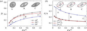
To examine the effects that the presence of the inner capsule has on the deformation of compound capsules, we plot the equilibrium deformation and orientation of the inner and outer capsules as functions of the outer capillary number
 $\mathit{Ca}^{out}$
at
 ${\it\phi}=0.05$
and
 ${\it\kappa}=1$
(figure 6). The deformation of a homogeneous capsule is also plotted for comparison. The deformation of both the inner and outer capsules monotonically increases with
 $\mathit{Ca}^{out}$
increasing (figure 6
a) whereas the orientation decreases (figure 6
b), which is the same qualitative tendency of the deformation and orientation as for the homogeneous capsule. Within the range of
 $\mathit{Ca}=0.05{-}1$
, the capsule with the inner capsule inside deforms less than that without the inner capsule (figure 6
a). This observation is similar to that of compound capsules under stretching in quiescent fluids (Hosseini & Feng Reference Hosseini and Feng2012), but it is contrary to the observation of compound droplets with uniform surface tension in extensional flows (Stone & Leal Reference Stone and Leal1990; Kan et al.
Reference Kan, Udaykumar, Shyy and Tran-Son-Tay1998; Qu & Wang Reference Qu and Wang2012). Besides, the inner capsule exhibits smaller deformation than both the outer capsule and the homogeneous capsule. The basic reason is that the smaller size of the inner capsule makes the membrane elastic tension more important, i.e.
 $\mathit{Ca}^{in}={\it\kappa}{\it\phi}^{1/3}\mathit{Ca}^{out}=0.37\mathit{Ca}^{out}$
for
 ${\it\phi}=0.05$
and
 ${\it\kappa}=1$
. In figure 6(b), the orientation of the outer capsule is slightly smaller than that of the homogeneous capsule. In contrast, the orientation of the inner capsule is much larger.
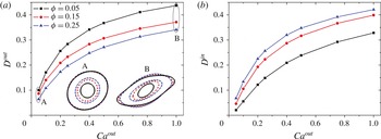
Figure 7 presents the deformations of the outer capsule
 $D^{out}$
and the inner capsule
 $D^{in}$
versus the outer capillary number
 $\mathit{Ca}^{out}$
for three different inner capsule sizes, i.e.
 ${\it\phi}=0.05$
, 0.15 and 0.25;
 ${\it\kappa}$
is fixed at 1. The same qualitative tendency, i.e.
 $D^{out}$
and
 $D^{in}$
monotonically increasing with
 $\mathit{Ca}^{out}$
increasing, is observed for the three cases of
 ${\it\phi}$
. However, increasing
 ${\it\phi}$
leads to a decrease in the deformation of the outer capsule at a given value of
 $\mathit{Ca}^{out}$
(figure 7
a). This tendency is also observed in the study on compound capsules under stretching in quiescent fluids (Hosseini & Feng Reference Hosseini and Feng2012). In contrast to the observation of the outer capsule, the inner capsule deforms to a greater degree with
 ${\it\phi}$
increasing at a given value of
 $\mathit{Ca}^{out}$
(figure 7
b). This is because the capillary number of the inner membrane
 $\mathit{Ca}^{in}$
increases with
 ${\it\phi}$
(
 $\mathit{Ca}^{in}={\it\kappa}{\it\phi}^{1/3}\mathit{Ca}^{out}$
) increasing at a given value of
 $\mathit{Ca}^{out}$
and
 ${\it\kappa}$
. It is noted that increasing
 ${\it\phi}$
has insignificant effects on
 $D^{out}$
when
 $\mathit{Ca}^{out}$
is small, e.g.
 $\mathit{Ca}^{out}=0.05$
(see the inset in figure 7
a). Varying the size of the inner capsule can affect the deformation of the outer capsule, because it induces changes in the flow field inside the outer capsule and hence influences the viscous forces on the outer membrane. However, when
 $\mathit{Ca}^{out}\ll 1$
, it has insignificant effects on the deformation of the outer capsule, since the outer capsule is hard to be deformed by the viscous forces of the external and internal flows. The reason is similar to why the internal fluid viscosity has insignificant effects on the capsule deformation when
 $\mathit{Ca}\ll 1$
(Barthes-Biesel & Rallison Reference Barthes-Biesel and Rallison1981; Foessel et al.
Reference Foessel, Walter, Salsac and Barthes-Biesel2011).
Deformation of (a) the outer capsule and (b) the inner capsule as functions of the capillary number of the outer membrane for various volume ratios at
 ${\it\kappa}=1$
.

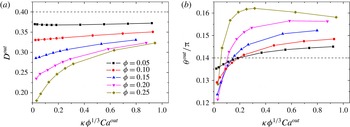
To investigate the effects of the inner capsule on the deformation of the outer capsule, we plot
 $D^{out}$
and
 ${\it\theta}^{out}$
of the outer capsule with
 $\mathit{Ca}^{out}=0.5$
as functions of
 $\mathit{Ca}^{in}={\it\kappa}{\it\phi}^{1/3}\mathit{Ca}^{out}$
in figure 8. The deformation of the outer capsule monotonically increases with the inner capillary number increasing for
 ${\it\phi}=0.1{-}0.25$
. Particularly, increasing
 $\mathit{Ca}^{in}$
significantly enlarges
 $D^{out}$
for large
 ${\it\phi}$
, whereas it has negligible effects for small
 ${\it\phi}$
. For instance,
 $D^{out}$
increases by 79 % with
 $\mathit{Ca}^{in}$
increasing from 0.032 to 0.94 for
 ${\it\phi}=0.25$
, whereas it increases merely by 0.8 % with
 $\mathit{Ca}^{in}$
increasing from 0.036 to 0.92 for
 ${\it\phi}=0.05$
(figure 8
a). However, the influence of the inner capillary number on the orientation of the outer capsule is more complex (figure 8
b). For
 ${\it\phi}=0.05{-}0.15$
,
 ${\it\theta}^{out}$
monotonically increases with
 $\mathit{Ca}^{in}$
increasing, whereas when
 ${\it\phi}=0.2{-}0.25$
, it increases sharply at first and then gradually decreases with
 $\mathit{Ca}^{in}$
increasing. Nevertheless, the influence of
 $\mathit{Ca}^{in}$
on
 ${\it\theta}^{out}$
is reduced by decreasing
 ${\it\phi}$
, which is similar to the influence of
 $\mathit{Ca}^{in}$
on
 $D^{out}$
.
(a) Deformation and (b) orientation of the outer capsule with
 $\mathit{Ca}^{out}=0.5$
as functions of the capillary number of the inner membrane
 $\mathit{Ca}^{in}={\it\kappa}{\it\phi}^{1/3}\mathit{Ca}^{out}$
for different volume ratios. The dashed lines represent the deformation and orientation of the homogeneous capsule with
 $\mathit{Ca}^{H}=0.5$
, which is
 $D^{H}=0.40$
and
 ${\it\theta}^{H}=0.14{\rm\pi}$
.

(a) Deformation and (b) orientation of the inner capsule at
 $\mathit{Ca}^{out}=0.5$
as functions of the capillary number of the inner membrane
 $\mathit{Ca}^{in}={\it\kappa}{\it\phi}^{1/3}\mathit{Ca}^{out}$
for different volume ratios. The inset in panel (a) is the deformation of the inner capsule with
 ${\it\phi}=0.05$
for
 $\mathit{Ca}^{out}=0.05{-}0.5$
.

Comparison of the deformation behaviours of the inner and outer capsules: (a) the ratio of the deformation indices and (b) the difference in the orientation angles at
 $\mathit{Ca}^{out}=0.5$
as functions of
 $\mathit{Ca}^{in}/\mathit{Ca}^{out}={\it\kappa}{\it\phi}^{1/3}$
. The insets show
 $D^{in}/D^{out}$
and
 ${\it\theta}^{in}-{\it\theta}^{out}$
as functions of
 $\mathit{Ca}^{out}$
at
 ${\it\phi}=0.15$
. (c–f) Shape contours of compound capsules with
 ${\it\phi}=0.2$
in panel (a) for
 ${\it\kappa}{\it\phi}^{1/3}=0.1170$
, 0.3509, 0.5848 and 1.1696, respectively. The arrowed lines are the major axes of the deformed shapes. To compare the deformation degree of the inner and outer capsules, the inner capsule is enlarged in proportion to have the same volume as the outer capsule and is also rotated to have the same inclination angle as the outer capsule. The shape of the inner capsule after the transformation is presented by the dashed lines.

Steady shapes of compound capsules at
 $\mathit{Ca}^{out}=0.5$
with different inner capsules. The steady shape of the homogeneous capsule at
 $\mathit{Ca}^{H}=0.5$
is presented for comparison.

Time evolutions of the phase angle and angular velocity of a tracked point on the membranes of compound capsules. (a) The time evolutions of the phase angle (
 ${\it\theta}_{p}$
), the angular velocity (
 $\text{d}{\it\theta}_{p}/\text{d}t$
) and the difference of the phase angle and inclination angle (
 ${\it\theta}_{p}-{\it\theta}$
) for the compound capsule with
 $\mathit{Ca}^{out}=0.5$
,
 ${\it\kappa}=1$
and
 ${\it\phi}=0.15$
. The equilibrium deformation of the compound capsule is
 $D^{out}=0.31$
and
 $D^{in}=0.32$
.
 ${\it\theta}_{p}$
is the angle between the flow direction (i.e. positive
 $X$
-axis) and the vector pointing from the capsule centre to the tracked point on the membrane. (b) The time evolution of the angular velocity for compound capsules with different
 $\mathit{Ca}^{out}$
when
 ${\it\kappa}=1$
and
 ${\it\phi}=0.25$
. The deformation of the compound capsule with
 $\mathit{Ca}^{out}=1$
, 0.5, 0.1 and 0.05, respectively, is
 $D^{out}=0.34$
and
 $D^{in}=0.42$
,
 $D^{out}=0.27$
and
 $D^{in}=0.35$
,
 $D^{out}=0.11$
and
 $D^{in}=0.13$
, and
 $D^{out}=0.06$
and
 $D^{in}=0.07$
.

Distribution of
 ${\it\lambda}_{1}/{\it\lambda}_{2}~({\it\lambda}_{1}\geqslant {\it\lambda}_{2})$
and
 ${\it\lambda}_{1}{\it\lambda}_{2}$
in the outer and inner membranes in the velocity–vorticity plane (i.e.
 $XY$
plane). For all cases,
 ${\it\kappa}=1$
. The values of the deformation indices are: (a)
 $D^{out}=0.34$
and
 $D^{in}=0.42$
, (b)
 $D^{out}=0.27$
and
 $D^{in}=0.35$
, (c)
 $D^{out}=0.11$
and
 $D^{in}=0.13$
, (d)
 $D^{out}=0.31$
and
 $D^{in}=0.32$
, and (e)
 $D^{H}=0.4$
.

Influences of the viscosity ratios on the deformation of compound capsules. (a,b) The deformations of homogeneous and compound capsules at
 ${\it\lambda}^{H}={\it\lambda}^{out}=0.2$
and
 ${\it\lambda}^{H}={\it\lambda}^{out}=5$
, respectively. For all cases in panels (a) and (b),
 ${\it\lambda}^{in}=1$
and
 ${\it\kappa}=1$
. (c,d) The deformations of compound capsules as functions of
 ${\it\lambda}^{in}$
and
 ${\it\lambda}^{out}$
, respectively. For all cases in panels (c) and (d),
 $\mathit{Ca}^{out}=1$
and
 ${\it\kappa}=1$
; for cases in (c),
 ${\it\lambda}^{out}=1$
; and for cases in (d),
 ${\it\lambda}^{in}=1$
.

We then analyse the deformation of the inner capsule by presenting
 $D^{in}$
and
 ${\it\theta}^{in}$
of the inner capsule as functions of the capillary number of the inner membrane
 $\mathit{Ca}^{in}={\it\kappa}{\it\phi}^{1/3}\mathit{Ca}^{out}$
(figure 9). The deformation of the homogeneous capsule is also plotted for comparison. At a given value of
 $\mathit{Ca}^{in}$
, increasing
 ${\it\phi}$
leads to a slight increase in
 $D^{in}$
and a significant decrease in
 ${\it\theta}^{in}$
. Besides,
 $D^{in}$
increases but
 ${\it\theta}^{in}$
decreases with
 $\mathit{Ca}^{in}$
increasing for each case of
 ${\it\phi}$
(figure 9
a,b). This is similar, in qualitative terms, to the tendency of
 $D^{H}$
and
 ${\it\theta}^{H}$
of the homogeneous capsule with
 $\mathit{Ca}^{H}$
increasing. Particularly, the deformation of the inner capsule for
 $\mathit{Ca}^{out}=0.5$
is close, in quantitative terms, to the deformation of the homogeneous capsule (figure 9
a), but the orientation is much larger (figure 9
b). It is shown that
 $D^{in}$
can be larger than
 $D^{H}$
for low
 $\mathit{Ca}^{in}$
and high
 ${\it\phi}$
. The possible reason is that the hydrodynamic interaction between the inner and outer membranes induces the increase of the inner capsule deformation (see § 5.2 for detailed discussion). Furthermore, as
 $\mathit{Ca}^{out}$
increases from 0.05 to 0.5 for
 ${\it\phi}=0.05$
,
 $D^{in}$
increases monotonically until it levels off (see the inset in figure 9
a). This result shows that the inner capsule is protected by the outer membrane from the external shear flow, and the protection is strengthened by decreasing the deformability of the outer membrane. Generally, the orientation angle is below
 ${\rm\pi}/4$
for spherical homogeneous capsules in simple shear flow with inertia neglected, i.e.
 $\mathit{Re}\ll 1$
(Barthes-Biesel & Rallison Reference Barthes-Biesel and Rallison1981; Foessel et al.
Reference Foessel, Walter, Salsac and Barthes-Biesel2011; Bai et al.
Reference Bai, Luo, Wang, He, Lu and Xu2013b
). One surprising observation in our present study is that the orientation angle of the inner capsule can be larger than
 ${\rm\pi}/4$
(e.g.
 ${\it\theta}^{in}=0.317{\rm\pi}-0.263{\rm\pi}$
for
 $\mathit{Ca}^{in}=0.018{-}0.184$
at
 ${\it\phi}=0.05$
and
 $\mathit{Ca}^{out}=0.5$
as shown in figure 9
b), but it is not observed for the outer capsule (figure 8
b). This is because the inner capsule deforms in rotational flow but the outer capsule deforms in simple shear flow (see § 5.1 for detailed discussion).
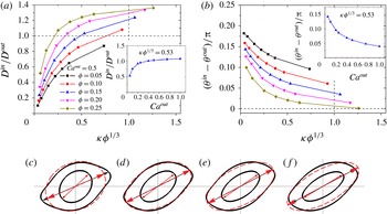
To compare the deformation of the inner and outer capsules, we plot
 $D^{in}/D^{out}$
and
 ${\it\theta}^{in}-{\it\theta}^{out}$
in figure 10 as functions of
 $\mathit{Ca}^{in}/\mathit{Ca}^{out}={\it\kappa}{\it\phi}^{1/3}$
. At a given value of
 $\mathit{Ca}^{out}=0.5$
, the increase of either
 $\mathit{Ca}^{in}/\mathit{Ca}^{out}$
or
 ${\it\phi}$
leads to a continuous increase of
 $D^{in}/D^{out}$
and a continuous decrease of
 ${\it\theta}^{in}-{\it\theta}^{out}$
(figure 10
a,b). As
 $\mathit{Ca}^{out}$
increases from 0.05 to 1 at a given value of
 ${\it\phi}=0.15$
,
 $D^{in}/D^{out}$
increases monotonically from 0.53 and reaches a plateau value of 1.07 (see the inset in figure 10
a), and
 ${\it\theta}^{in}-{\it\theta}^{out}$
decreases monotonically from
 $0.142{\rm\pi}$
until a level of
 $0.022{\rm\pi}$
(see the inset in figure 10
b). Previous studies on the deformation of homogeneous capsules in simple shear flow (Barthes-Biesel & Rallison Reference Barthes-Biesel and Rallison1981; Foessel et al.
Reference Foessel, Walter, Salsac and Barthes-Biesel2011) reveal that the capsule deformation is determined by the capillary number when the viscosity ratio of the internal to the external fluid is fixed at 1. The deformation of capsules in simple shear flow is larger when the capillary number is higher. Interestingly, for
 $\mathit{Ca}^{in}/\mathit{Ca}^{out}=1$
,
 $D^{in}/D^{out}$
is larger than 1 when
 ${\it\phi}=0.15{-}0.25$
(figure 10
a). In previous studies on the deformation of compound droplets in extensional flows (Stone & Leal Reference Stone and Leal1990; Kan et al.
Reference Kan, Udaykumar, Shyy and Tran-Son-Tay1998; Qu & Wang Reference Qu and Wang2012), the deformation of the inner drop was not observed to be larger than that of the outer drop, partly because
 $\mathit{Ca}^{in}/\mathit{Ca}^{out}$
was limited to be below 1. In figure 10(a), it is noted that the deformation of the inner capsule with
 ${\it\phi}=0.25$
can be still larger than the deformation of the outer capsule even when
 $\mathit{Ca}^{in}/\mathit{Ca}^{out}$
is as low as 0.25. Shape contours of the compound capsules with
 ${\it\phi}=0.2$
for different cases of
 $\mathit{Ca}^{in}/\mathit{Ca}^{out}$
are presented in figure 10(c–f). The inner capsule is more slender than the outer capsule when
 $\mathit{Ca}^{in}/\mathit{Ca}^{out}=0.5848$
(figure 10
e), which indicates that the inner capsule deforms to a greater degree than the outer capsule. These observations suggest that Kaoui et al.’s (Reference Kaoui, Kruger and Harting2013) statement that the inner capsule is less deformable than the outer capsule (which functions as a nearly solid obstacle) is questionable.
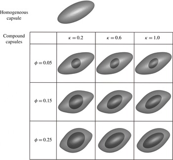
To give a more direct illustration of the deformation of the compound capsule, the steady shapes of the inner and outer capsules are presented in figure 11. It has long been found that initially spherical homogeneous capsules in simple shear flow deform to a nearly ellipsoidal steady shape (Ramanujan & Pozrikidis Reference Ramanujan and Pozrikidis1998; Lac et al.
Reference Lac, Barthes-Biesel, Pelekasis and Tsamopoulos2004; Li & Sarkar Reference Li and Sarkar2008). In our study on compound capsules, the inner capsule assumes a nearly ellipsoidal steady shape similar to that of the homogeneous capsule. However, the steady shape of the outer capsule can be quite different from the ellipsoidal shape of the inner capsule, when the inner capsule is large enough and the inner membrane is stiff enough. For example, when
 ${\it\phi}=0.25$
and
 ${\it\kappa}=0.2$
(i.e.
 $\mathit{Ca}^{in}={\it\kappa}{\it\phi}^{1/3}\mathit{Ca}^{out}=0.063$
), sharp tips are observed at the two ends of the outer capsule. The sharp tips probably lead to new dynamical states of non-spherical compound capsules, e.g. wrinkling of the membrane or formation of four lobes observed in the study of 2D compound capsules (Kaoui et al.
Reference Kaoui, Kruger and Harting2013). Nevertheless, the outer capsule also deforms to a nearly ellipsoidal steady shape when the inner capsule is sufficiently small or is sufficiently deformed.
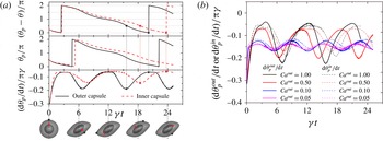
Time evolutions of the phase angle and angular velocity of a tracked point on the membrane are presented in figure 12 to compare the rotating speeds of the inner and outer membranes. For the two membranes of the compound capsule (figure 12 a), the angular velocity of the tracked point varies along the membrane. It is maximum on the minor axis (i.e. at the equator) and is minimum on the major axis (i.e. at the tip), which is similar to the observation of homogeneous capsules (Keller & Skalak Reference Keller and Skalak1982). The difference in the maximum and minimum values of the angular velocity decreases with decreasing capsule deformation (figure 12 b). It is noteworthy that the angular velocity of the inner membrane is lower than that of the outer membrane, especially at the equator (figure 12 a), and the tank-treading period of the inner membrane is longer. This means that the rotations of the inner and outer membranes are desynchronized, i.e. the outer membrane rotates faster. This desynchronization of the rotation can be lessened by decreasing the deformation of the outer capsule, inside which the flow is more like pure rotational flow. In figure 12(b), it is also noted that the difference of the tank-treading period and the angular velocity between the inner and outer membranes decreases with decreasing capillary number of the outer membrane.
Tensions in the membranes of homogeneous capsules were previously presented by Omori et al. (Reference Omori, Ishikawa, Barthes-Biesel, Salsac, Imai and Yamaguchi2012, Reference Omori, Ishikawa, Imai and Yamaguchi2013), as they are important for exploring the mass transfer crossing the membranes. Here, in figure 13, we present the distribution of strains (i.e.
 ${\it\lambda}_{1}/{\it\lambda}_{2}$
and
 ${\it\lambda}_{1}{\it\lambda}_{2}$
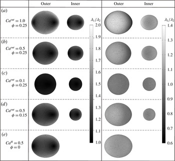
) in the inner and outer membranes of compound capsules. For both the inner and outer membranes,
 ${\it\lambda}_{1}/{\it\lambda}_{2}$
is maximum at the tip. This is similar to the observation of homogeneous capsules (figure 13
e), which was also presented in previous numerical studies (Foessel et al.
Reference Foessel, Walter, Salsac and Barthes-Biesel2011; Omori et al.
Reference Omori, Ishikawa, Barthes-Biesel, Salsac, Imai and Yamaguchi2012, Reference Omori, Ishikawa, Imai and Yamaguchi2013). Both
 ${\it\lambda}_{1}/{\it\lambda}_{2}$
and
 ${\it\lambda}_{1}{\it\lambda}_{2}$
decrease with decreasing capsule deformation
 $D$
(figure 13
a–c). The inner membrane of compound capsules has comparable
 ${\it\lambda}_{1}/{\it\lambda}_{2}$
and
 ${\it\lambda}_{1}{\it\lambda}_{2}$
with the membrane of homogeneous capsules (figure 13
a,e), when their deformation index is close. However, the outer membrane can present higher
 ${\it\lambda}_{1}/{\it\lambda}_{2}$
and
 ${\it\lambda}_{1}{\it\lambda}_{2}$
, especially at the capsule equator, than both the inner membrane and the membrane of homogeneous capsules, even when the deformation index
 $D$
is lower – for example, see the outer membrane in figure 13(a), the inner membrane in figure 13(b) and the membrane of homogeneous capsules in figure 13(e). This can be explained by the fact that the inner capsule has an ellipsoidal steady shape similar to the steady shape of the homogeneous capsule, whereas the outer capsule is more convex at the equator owing to the presence of the inner capsule (figure 11).
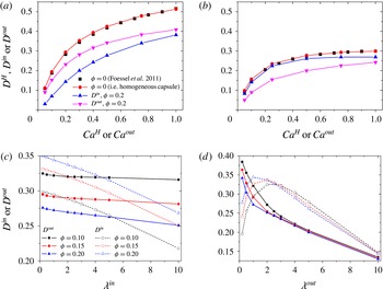
We also investigate the effects of viscosity ratios on the deformation of compound capsules (figure 14). The present modelling of capsules with non-unity viscosity ratios is validated by comparing the prediction of the deformation of homogeneous capsules at
 ${\it\lambda}^{H}=0.2$
(figure 14
a) and 5 (figure 14
b) with the results by Foessel et al. (Reference Foessel, Walter, Salsac and Barthes-Biesel2011). For compound capsules with outer viscosity ratio
 ${\it\lambda}^{out}=0.2$
(figure 14
a) and 5 (figure 14
b) and inner viscosity ratio
 ${\it\lambda}^{in}=1$
, the deformation of the outer capsule is smaller than that of the homogeneous capsule with viscosity ratio the same as the outer viscosity ratio. This further indicates that the presence of the inner capsule prevents the whole compound capsule from deforming. It is noted that the inner capsule exhibits smaller deformation than the outer capsule at
 ${\it\lambda}^{out}=0.2$
but larger at
 ${\it\lambda}^{out}=5$
. This is because the outer viscosity ratio determines the inner capillary number (i.e.
 $\mathit{Ca}^{in}={\it\lambda}^{out}{\it\kappa}{\it\phi}^{1/3}\mathit{Ca}^{out}$
). For compound capsules with
 ${\it\phi}=0.2$
and
 ${\it\kappa}=1$
, the inner capillary number is lower than the outer one at
 ${\it\lambda}^{out}=0.2~(\mathit{Ca}^{in}=0.12\mathit{Ca}^{out})$
but higher at
 ${\it\lambda}^{out}=5~(\mathit{Ca}^{in}=2.92\mathit{Ca}^{out})$
. The deformations of the inner and outer capsules are also plotted as functions of
 ${\it\lambda}^{in}$
and
 ${\it\lambda}^{out}$
in figure 14(c,d). As
 ${\it\lambda}^{in}$
increases with
 ${\it\lambda}^{out}$
maintained constant at 1, the deformations of both the inner and outer capsules decreases, but
 $D^{in}$
decreases more significantly than
 $D^{out}$
. As
 ${\it\lambda}^{out}$
increases with
 ${\it\lambda}^{in}$
maintained constant at 1, the outer capsule deformation decreases continuously similar to the homogeneous capsule deformation (Foessel et al.
Reference Foessel, Walter, Salsac and Barthes-Biesel2011), whereas the inner capsule deformation first increases and then decreases. For low
 ${\it\lambda}^{out}$
,
 $D^{in}$
increases with
 ${\it\lambda}^{out}$
owing to the increase of the inner capillary number, whereas
 $D^{in}$
decreases for high
 ${\it\lambda}^{out}$
because
 $D^{in}$
decreases with
 $D^{out}$
when
 $D^{out}$
is small, as presented in the inset of figure 9(a). In conclusion, the inner capsule deformation shows a strong dependence on both the inner and outer viscosity ratios, and the outer capsule deformation depends on the outer viscosity ratio more than on the inner viscosity ratio.
5. Discussion
5.1. Effects of the outer membrane on the flow inside the outer capsule
For capsules in general flow with velocity
 $\boldsymbol{u}$
, the linear shear
 $\boldsymbol{{\rm\nabla}}\boldsymbol{u}=\boldsymbol{e}+{\bf\omega}$
(
 $\boldsymbol{e}$
and
 ${\bf\omega}$
are the rate of strain and vorticity tensors unified by the shear rate
 ${\it\gamma}$
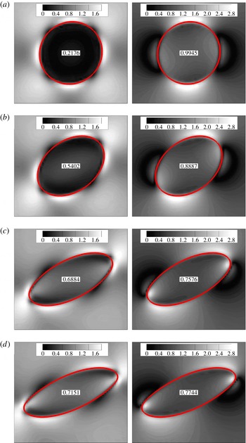
) is responsible for deforming the capsule shape (Rallison Reference Rallison1984). In particular, the rate of strain induces the capsule deformation, whereas the vorticity inhibits the capsule deformation if it is not parallel to the principal extension (Olbricht, Rallison & Leal Reference Olbricht, Rallison and Leal1982; Rallison Reference Rallison1984). In our cases, it is observed that, owing to the outer membrane, the rate of strain of the flow inside the outer capsule (in which the inner capsule is suspended) is smaller than that of simple shear flow outside the outer capsule (figure 15). Hence, the effective capillary number of the inner capsule is more appropriately expressed in the form
 $\mathit{Ca}^{in}={\it\kappa}{\it\phi}^{1/3}{\it\mu}({\it\beta}{\it\gamma})R/G_{s}^{out}$
, where
 ${\it\beta}<1$
represents the decrease of the rate of strain of the flow inside the outer capsule. This expression was mentioned by Stone & Leal (Reference Stone and Leal1990) in their study on the breakup of compound droplets in extensional flows.
The difference of the largest and smallest principal rates of strain
 $e_{max}-e_{min}$
(left panels) and the vorticity magnitude (right panels) inside and outside homogeneous capsules with (a)
 $\mathit{Ca}^{H}=0.01$
, (b) 0.1, (c) 0.5 and (d) 1.0. The numbers are corresponding values in the centre of the capsule. The rate of strain and vorticity unified by the shear rate are 1 when no capsule is present in simple shear flow.

Next we discuss the effects of the outer membrane and its shape on
 ${\it\beta}$
. As a consequence of the shearing of the external flow on the outer membrane, flows parallel to the outer membrane are induced inside the outer capsule and hence rotational flow is developed. If the outer capsule exhibits negligible deformation (i.e.
 $\mathit{Ca}^{out}\ll 1$
) and maintains a purely spherical shape, it follows that the internal flow is purely rotational (i.e.
 $\boldsymbol{e}=0$
); thus the inner capsule shows negligible deformation (i.e.
 ${\it\beta}\ll 1$
). As the outer capsule presents larger deformation (i.e.
 $\mathit{Ca}^{out}$
increases), its non-spherical shape no longer permits pure rotational flow inside (i.e.
 ${\it\beta}$
increases). When the outer capsule deforms to an extremely high degree (e.g.
 $D^{out}=0.4$
for
 $\mathit{Ca}^{out}=0.5$
in figure 15
c), the rate of strain of the flow near the capsule centre is close to that of simple shear flow (i.e.
 ${\it\beta}$
approaches 1). Previous small-deformation theories show that the deformation of small deformable particles increases with the increase of
 $e_{max}-e_{min}$
, where
 $e_{max}$
and
 $e_{min}$
are the largest and smallest principal rates of strain, respectively (Rallison Reference Rallison1984). We find that
 $e_{max}-e_{min}$
increases with the increase of the outer capsule deformation (figure 15). These observations suggest that
 ${\it\beta}$
is below 1 due to the presence of the outer membrane and it decreases to 0 as the deformation of the outer capsule decreases to 0. In figure 15, as the capillary number increases from 0.05 to 0.5, the vorticity magnitude decreases with the increase of the outer capsule deformation, which was proposed as the main reason for the smaller deformation of the inner drop (Chen et al.
Reference Chen, Liu and Shi2013). However, it is also noted that the vorticity magnitude increases as the capillary number further increases from 0.5 to 1, and it is expected to converge to 1 when the capillary number becomes infinite. Therefore, we conclude that the decrease of the rate of strain inside the outer capsule is the main reason for the smaller deformation of the inner capsule rather than the increase of the vorticity as proposed by Chen et al. (Reference Chen, Liu and Shi2013).
5.2. Hydrodynamic interaction between the inner and outer membranes
It is worthy of note that increasing the size of the inner capsule and the deformations of the inner and outer capsules promotes their membranes to approach each other, so that significant hydrodynamic interaction occurs between them. Previous researchers mentioned that this hydrodynamic interaction plays an important role in the deformation and dynamics of compound capsules or compound droplets (Stone & Leal Reference Stone and Leal1990; Smith et al.
Reference Smith, Ottino and de la Cruz2004; Veerapaneni et al.
Reference Veerapaneni, Young, Vlahovska and Blawzdziewicz2011; Qu & Wang Reference Qu and Wang2012; Chen et al.
Reference Chen, Liu and Shi2013). Generally, the capsule shape is determined by the balance between the jump in stress
 ${\bf\sigma}$
across the membrane
 $[{\bf\sigma}^{ext}-{\bf\sigma}^{int}]\boldsymbol{\cdot }\boldsymbol{n}$
and the elastic load from membrane elastic tensions (Barthes-Biesel & Rallison Reference Barthes-Biesel and Rallison1981; Foessel et al.
Reference Foessel, Walter, Salsac and Barthes-Biesel2011). The stress
 ${\bf\sigma}$
of fluid flow is made up of pressure and viscous stresses. The stresses outside and inside the capsule (i.e.
 ${\bf\sigma}^{ext}$
and
 ${\bf\sigma}^{int}$
) in non-dimensional form are as follows:
 $$\begin{eqnarray}\left.\begin{array}{@{}l@{}}{\bf\sigma}^{ext}=-p\boldsymbol{I}+(\boldsymbol{{\rm\nabla}}\boldsymbol{u}+\boldsymbol{{\rm\nabla}}\boldsymbol{u}^{\text{T}}),\\ {\bf\sigma}^{int}=-p\boldsymbol{I}+{\it\lambda}(\boldsymbol{{\rm\nabla}}\boldsymbol{u}+\boldsymbol{{\rm\nabla}}\boldsymbol{u}^{\text{T}}).\end{array}\right\}\end{eqnarray}$$
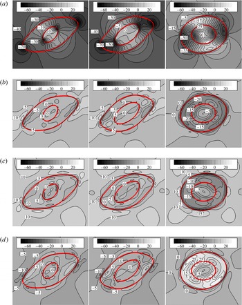
Figures 16 and 17 demonstrate our analysis of the hydrodynamic interaction in terms of the distribution of pressure and viscous stresses inside and outside the compound capsule. It should be noted that there is supposed to be a stress discontinuity across the two membranes due to membrane elastic tensions. However, in the front tracking method, quantities (including pressure and fluid viscosity) that tend to jump suddenly at an infinitely thin membrane change continuously over several Eulerian grid points crossing the membrane to avoid numerical instability. Thus, the fields of pressure and viscous stresses are continuous and smooth across the two membranes, as shown in figures 16 and 17. We find that the distributions of the stresses inside the inner capsule and outside the outer capsule are similar to those inside and outside the homogeneous capsule (figure 17), respectively. Hence, the hydrodynamic interaction is primarily reflected by the distribution of the stresses in the fluid layer between the two membranes, which is significantly affected by the inner capsule size and the deformations of the inner and outer capsules (figures 16 and 17).
Distributions of dimensionless pressure and viscous stresses inside and outside the compound capsules: (a)
 $p$
; (b)
 ${\it\mu}\,\partial u/\partial x$
; (c)
 $({\it\mu}/2)(\partial u/\partial z+\partial w/\partial x)$
; and (d)
 ${\it\mu}\,\partial w/\partial z$
. For all cases,
 $\mathit{Ca}^{out}=0.5$
,
 ${\it\kappa}=1$
,
 ${\it\lambda}^{in}=1$
; left panels,
 ${\it\phi}=0.05$
and
 ${\it\lambda}^{out}=1$
; middle panels,
 ${\it\phi}=0.15$
and
 ${\it\lambda}^{out}=1$
; and right panels,
 ${\it\phi}=0.15$
and
 ${\it\lambda}^{out}=10$
. The values are relative deviations from the stresses at the capsule centre.

Dimensionless pressure field inside and outside the inner and outer capsules: (a–c) capsules at
 $\mathit{Ca}^{out}=0.5$
and
 ${\it\kappa}=1$
with
 ${\it\phi}=0$
, 0.05 and 0.15, respectively; (d–f) capsules at
 ${\it\phi}=0.25$
, with (d)
 $\mathit{Ca}^{out}=0.5$
and
 $\mathit{Ca}^{in}={\it\kappa}{\it\phi}^{1/3}\mathit{Ca}^{out}=0.063$
, (e)
 $\mathit{Ca}^{out}=0.5$
and
 $\mathit{Ca}^{in}=0.315$
, and ( f)
 $\mathit{Ca}^{out}=0.1$
and
 $\mathit{Ca}^{in}=0.315$
. The values of the deformation indices are: (a)
 $D^{H}=0.4$
, (b)
 $D^{out}=0.37$
and
 $D^{in}=0.24$
, (c)
 $D^{out}=0.31$
and
 $D^{in}=0.32$
, (d)
 $D^{out}=0.2$
and
 $D^{in}=0.16$
, (e)
 $D^{out}=0.27$
and
 $D^{in}=0.35$
, and ( f)
 $D^{out}=0.15$
and
 $D^{in}=0.24$
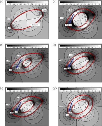
. The pressure values are relative deviations from pressure at the centre point of the compound capsule. The arrowed lines indicate the pressure gradient pointing from the capsule equator to the tip.

To compare the effects of pressure and viscous stresses on the compound capsule deformation, the distributions of pressure and viscous stresses inside and outside the compound capsule in the shear plane are presented separately in figure 16. It is noted that, when the viscosity ratio is unity, the increase of the inner capsule size has significant effects on the pressure distribution in the fluid layer between the two membranes, but has insignificant effects on the viscous stress distribution. Hence, the hydrodynamic interaction between the two membranes can be mainly reflected by the pressure distribution. However, the effects of viscous stresses become more significant when the viscosity ratio is higher, as shown in (5.1) and figure 16.
Thus the following discussion focuses on how the hydrodynamic interaction affects the deformations of the inner and outer capsules in terms of the pressure distribution in the fluid layer between the two membranes (figure 17). As presented in figure 17(b–f), there is a low-pressure region near the capsule tip and a high-pressure region near the equator; thus a pressure gradient directed from the capsule equator to the tip is formed. For the outer capsule, as the pressure gradient increases,
 ${\bf\sigma}^{int}$
increases at the equator, leading to a more convex shape of the capsule equator (i.e. increasing curvature), but decreases at the tip, leading to a less convex shape of the tip (i.e. decreasing curvature), thereby inducing the decrease in the global deformation of the outer capsule (figure 17). In contrast, the increase of the pressure gradient induces the increase in the global deformation of the inner capsule, since a higher pressure gradient results in higher
 ${\bf\sigma}^{ext}$
at the equator but lower
 ${\bf\sigma}^{ext}$
at the tip for the inner capsule. In figure 17, it is noted that the pressure gradient increases as the inner capsule size becomes larger or as the capillary number of the outer or the inner membrane becomes higher. In consequence, the outer capsule deformation decreases but the inner capsule deformation increases. A similar pressure gradient was also observed in the fluid layer between the capsule membrane and the channel walls when a homogeneous capsule is deformed in confined channels (Kaoui, Harting & Misbah Reference Kaoui, Harting and Misbah2011; Kaoui, Kruger & Harting Reference Kaoui, Kruger and Harting2012; Luo et al.
Reference Luo, He, Xu and Bai2015). The pressure gradient increased with increasing confinement, leading to the increase in the deformation of the capsule confined in the channels. This previous observation is similar to the findings regarding an inner capsule confined inside an outer membrane in our present study.
5.3. Analysis of mutual effects of inner and outer capsules on their deformation
Our observations about the deformations of the inner and outer capsules can be explained according to the two above-mentioned mechanisms, i.e. rotational flow inside the outer capsule and the hydrodynamic interaction between the inner and outer membranes. When the inner capsule is small, the hydrodynamic interaction between the inner and outer membranes is relatively weak and the deformation of the inner capsule is dominated by rotational flow inside the outer capsule. In this case, the inner capsule exhibits smaller deformation than the homogeneous capsule in simple shear flow (see the inset in figure 9 a), for the flow inside the outer capsule behaves much like rotational flow when the deformation of the outer capsule is small. As the deformation of the outer capsule increases, the rate of strain of the flow inside increases (figure 15), leading to the increase in the deformation of the inner capsule (see the inset in figure 9 a). When the deformation of the outer capsule is large, the flow inside the outer capsule behaves like simple shear flow (figure 15 c,d); in consequence, the deformation of the inner capsule is comparable to the deformation of the homogeneous capsule in simple shear flow (figure 9 a). When the volume ratio of the inner to the outer capsule becomes larger (i.e. the inner and outer membranes are closer), the hydrodynamic interaction between the two membranes becomes stronger (figure 17) and plays an important role. Therefore, the deformation of the outer capsule decreases with the increase of the volume ratio (figure 8 a), but the deformation of the inner capsule increases (figure 9 a). For a given value of the volume ratio, smaller deformation of the inner capsule results in stronger hydrodynamic interaction (figure 17). Thus, the outer capsule deformation decreases with the decrease of the inner capsule deformation, especially when the inner capsule is large (figure 8 a). In summary, when the inner capsule is small, it exhibits a smaller deformation than the outer capsule (figure 10 a), as the inner capsule is suspended in rotational flow whereas the outer capsule is in simple shear flow. However, the inner capsule can deform to a greater degree than the outer capsule as the inner capsule becomes larger (figure 10 a) owing to the growing hydrodynamic interaction between the two membranes. Nevertheless, the ratio of the inner capsule deformation to the outer capsule deformation is expected to converge to 1 when the inner capsule is almost of the same size as the outer capsule. Our future studies will be focused on research in this respect.
The inner and outer capsules also have significant effects on their orientation angle. The inner capsule is deformed by the shear flow, with its flow direction aligning with the major axis of the outer capsule. This means that an angle, termed the outer orientation angle, is formed by the principal extension axes of the flow deforming the inner capsule and the flow deforming the outer capsule. Accordingly, the major axes of the inner and outer capsules also form an angle (figures 7
b and 10
b). Thus the angle between the major axis of the inner capsule and the
 $X$
-axis, which is defined as the inner orientation angle, can be larger than
 ${\rm\pi}/4$
(figure 9
b), especially for low volume ratios. When the inner capsule is large, the hydrodynamic interaction between the two membranes significantly affects the orientation of the inner and outer capsules. As the two membranes approach each other, a high-pressure region between the two membranes at the capsule equator (figure 17) acts as a repulsive force to push the two capsules away from each other. Therefore, as the volume ratio of the inner capsule increases, the inner orientation angle decreases (figure 9
b) but the outer orientation angle increases (figure 8
b) due to the growing hydrodynamic interaction in between (figure 17). In addition, the hydrodynamic interaction tends to align the inner capsule with the flow inside the outer capsule so that the angle between the major axes of the inner and outer capsules decreases with increasing inner capsule size (figure 10
b). In previous numerical studies of homogeneous capsules deformed by simple shear flow in confined channels, the hydrodynamic interaction between the channel walls and the capsule was also observed to align the capsule with the flow (Kaoui et al.
Reference Kaoui, Harting and Misbah2011, Reference Kaoui, Kruger and Harting2012; Luo et al.
Reference Luo, He, Xu and Bai2015). For compound capsules, the inner capsule deforms in the shear flow confined by the outer membrane. It should be noted that the orientation angle of the outer capsule no longer increases with increasing inner capsule size when the inner capsule is hard to deform (figure 8
b). This may be due to the large departure of the outer capsule shape from an ellipsoid.
5.4. Future work on compound capsules in flows
Our present study reveals the deformation of compound capsules in simple shear flow by using 3D simulations. More research effort is needed in our future work to better apply our fundamental research to real-world applications. Compound capsules are considered as model systems to study the dynamics of eukaryotic cells (e.g. leukocytes and cancer cells) or parasite-infected RBCs in blood flow (Veerapaneni et al.
Reference Veerapaneni, Young, Vlahovska and Blawzdziewicz2011; Hosseini & Feng Reference Hosseini and Feng2012; Kaoui et al.
Reference Kaoui, Kruger and Harting2013; Abreu et al.
Reference Abreu, Levant, Steinberg and Seifert2014; Levant & Steinberg Reference Levant and Steinberg2014). It should be noted that biological membranes, including cell membranes, nucleus membranes and parasite membranes, are surface-area-inextensible, but the constitutive law (
 $C=1$
in the SK law) in our study holds for extensible membranes. Our future research will also need to address more complex mechanical properties of biological membranes, such as membrane bending stiffness and membrane viscosity. For studies on leukocytes and cancer cells, viscosity ratios much higher than unity and even the non-Newtonian nature of intracellular fluids will have to be taken into account. Furthermore, as demonstrated in the experiments by Chu et al. (Reference Chu, Utada, Shah, Kim and Weitz2007), artificial compound capsules used for the controlled release of active substances can be fabricated from multilayer emulsions in microfluidics by performing the polymerization reaction in specific layers. In this case, much more complex internal structures, e.g. multilayer structures and multiparticle structures, can be present inside the capsule. Consequently, in our future work, Eulerian resolutions of the numerical method need to be significantly improved.
6. Conclusions
In this study, we investigate the deformation of a compound capsule (an elastic capsule encapsulating a smaller elastic capsule) in simple shear flow by using 3D numerical simulations based on the front tracking method. Compound capsules deform with mechanisms quite different from those of homogeneous capsules, especially when the inner capsule is large and the inner membrane is stiff. Generally, the overall deformation of compound capsules is smaller than that of homogeneous capsules. The capillary numbers of the inner and outer membranes and the inner capsule size significantly affect the deformations of both the inner and outer capsules. In particular, as the inner capsule size increases, the deformation of the outer capsule decreases whereas the deformation of the inner capsule increases. Two mechanisms are discussed to explain the deformation of the compound capsule: (i) the flow around the inner capsule is rotational flow with the rate of strain lower than that of simple shear flow around the outer capsule, and thus the inner capsule exhibits smaller deformation than the outer capsule when the inner capsule is small; and (ii) when the inner capsule is large, the hydrodynamic interaction between the inner and outer membranes (i.e. the pressure gradient, directed from the equator to the tips of the capsule in the fluid layer between the two membranes) becomes significant, which reduces the deformation of the outer capsule but promotes the deformation of the inner capsule. Therefore, the inner capsule exhibits larger deformation than the outer capsule when the inner capsule is sufficiently large, even if the capillary number of the inner membrane is much lower than that of the outer membrane.
Acknowledgement
This work was supported by the China National Funds for Distinguished Young Scientists (51425603).