Introduction
Considerably great capacity, strong reliability, wide bandwidth, and low latency are the technological expectations of current tech savvy generation. 5G technology has opened a gateway with new-fangled operating bands which mitigate the bandwidth glitches of the present 4G era. Therefore, voluminous research has been carried out to make transition from 4G to 5G. Also, it is strongly anticipated that the future Internet of things (IoT) will be supported by upcoming 5G technology. To make the dream of 5G-IoT true, substantial research needs to be conducted within and across all the technological aspects of wireless communication systems, hence provides impetus to design compact multiband antennas which cover the current and upcoming standards.
Ample of multiband antenna designs operating at microwave and millimeter (mm) wave frequencies separately have been demonstrated in [Reference Qi, Li and Liu1–Reference Sedghi, Shafei, Kalami and Aribi9] and [Reference Marzouk, Ahmed and Shaalan10, Reference Khattak, Sohail, Khan, Barki and Witjaksono11], respectively. Conductor-backed planes are incorporated in multiband antennas [Reference Verma and Kumar8, Reference Sedghi, Shafei, Kalami and Aribi9] to control different microwave bands whereas slot antennas and antenna arrays are used to achieve microwave and mm-wave frequency re-configurability in 4G/5G mobile handsets [12]. Recently, few antenna designs [13-16] have also been proposed which cover both the microwave and mm-wave bands simultaneously. An ultra-wideband antipodal Vivaldi antenna for mm and microwave imaging applications with bandwidth from 5 to 50 GHz is presented in [13] and a dual-element MIMO antenna comprising intricate structure is presented in [14] for the 4G standard 1870–2530 MHz and mm-wave 5G band 26–28.4 GHz. A 4G/5G triple-band antenna consisting of an Franklin monopole antenna operating at 2.4/5.5 GHz and a 5G rectangular patch antenna operating at 28 GHz is introduced in [15] with both antenna parts isolated through a low-profile microstrip resonant cell low pass filter and Kurvinen et al. [16] showed a triple-band LTE and mm-band antenna for mobile handsets operating at two microwave bands 700–960 and 1710–2690 MHz and mm-wave band 25–30 GHz. An integrated antenna system operating at 3.5, 5.5, and 26/28 GHz is presented in [17] which consists of antenna arrays with defected ground structure.
As very limited research is available in the literature which covers both the microwave and mm-wave bands simultaneously, therefore as an additional contribution, compact dual-band and triple-band printed antennas are presented in this paper which operate at 5.8/28 GHz and 3.5/5.8/28 GHz, respectively. The organization of the paper is done meticulously as below. Section “Antenna design and configuration” describes the step-by-step design and structure of antennas. Discussion on simulated as well as measured results are detailed in Section “Results and discussion.” Finally, epilog is presented in Section “Conclusion.” Designing and study of antenna is done using computer simulation technology (CST) software followed by measurement using a vector network analyzer (VNA) (Anritsu MS46322B) and anechoic chamber.
Antenna design and configuration
A dual-band antenna consisted of a printed dipole and a monopole of quarter wavelength (Lm1) at the top is designed to operate at 28 GHz and 5.8 GHz with the geometry shown in Fig. 1. The proposed design is printed on Rogers RT5880LZ of thickness 0.254 mm with relative permittivity and tangent loss of 2 and 0.0021, respectively. The initial lengths of dipole (la) and monopole (Lm1) are approximately calculated as [18]:


Here, c stands for speed of light, i.e. 3 × 10⁸ m/s, f r is the frequency of resonance, and ɛ r and ɛ reff are the substrate's relative and relative effective permittivity, respectively. The optimized dimensions of the proposed dual-band antenna are ls = 18 mm, ws = 16 mm, wf = 0.77 mm, Gh = 4 mm, lp = 5 mm, wp = 0.4 mm, la = 2.8 mm, and Lm1 = 11.7 mm.
Projected dual-band antenna.

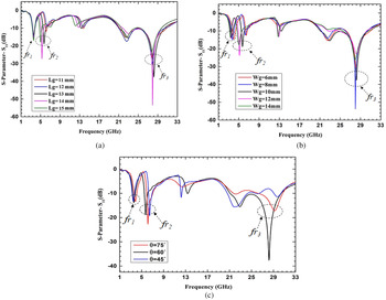
Further, another monopole of length Lm2 is implemented to achieve third resonance at 3.5 GHz and the length Lm2 is calculated using equation (2). To make antenna more rugged, the triple-band antenna is designed on a thicker Rogers RT5880LZ substrate of thickness 0.508 mm. The monopoles at the front side and additional conducting plane at the bottom side are placed appropriately at optimized positions to have triple-band operation and the complete geometry of the projected triple-band antenna is shown in Fig. 2. In the design, the angle between two monopoles (θ) and conducting back plane play a significant role in tuning and controlling all the three desired frequencies. The effect of length (Lg) and width (Wg) of conducting back plane, and the angle (θ) on the antenna operating frequencies is shown using parametric studies in Fig. 3. It is observed that the change in Lg and Wg shifts the lower resonances and has little impact on high frequency, whereas the third controlling parameter θ has effects on all the three frequencies. The optimized dimensions of modified antenna are Ls = 25 mm, Ws = 30 mm, Lp = 5 mm, La = 3.5 mm, Lm1 = 8.4 mm, Lm2 = 14.23 mm, Lc = 0.464 mm, Wm = 1.3 mm, Lg = 13 mm, Wg = 10 mm, Gh = 4.5 mm, Wf = 1.5 mm, and θ = 60°.
Geometry of the projected triple-band antenna: (a) front vision and (b) rear vision.

(a) Effect of Lg. (b) Effect of Wg. (c) Effect of θ.

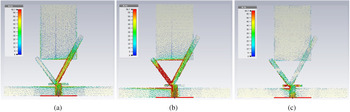
The simulated excited surface current distributions are shown at three operating frequencies in Fig. 4 to obtain a good physical insight of the operation of the antenna. It is well seen from Figs 4(a) and 4(b) that current is mainly flowing through right and left monopole striplines at microwave frequencies 3.5 GHz and 5.8 GHz, respectively and most of the current passes through dipole arms for the upper mm-wave band (28 GHz) as shown in Fig. 4(c). Thus, it is evident that the right and left monopoles are responsible for operating at 3.5 GHz and 5.8 GHz, whereas dipole is responsible to operate at 28 GHz.
Simulated current distribution of triple-band antenna: (a) fr 1 = 3.5 GHz; (b) fr 2 = 5.8 GHz; and (c) fr 3 = 28 GHz.

Results and discussion
The proposed dual and triple-band antenna designs have been implemented using the photolithographic technique.
Dual-band antenna
The measured S-parameter (S 11) of the projected dual-band antenna is −17.8 and dB−24.27 dB at 5.8 GHz and 28 GHz, respectively with the corresponding −10 dB impedance bandwidth of 560 MHz and 5.65 GHz as shown in Fig. 5.
Simulated and measured S-parameter (S 11) of the projected dual-band antenna.

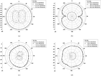
The simulated as well as measured co and cross radiation distribution in the E and H planes are shown in Fig. 6. At the lower operating frequency (5.8 GHz), the radiation pattern is closely omni-directional in the E-plane and bidirectional in the H-plane as shown in Figs 6(a) and 6(b), while at 28 GHz the antenna exhibits directional patterns in both the planes as shown in Figs 6(c) and 6(d). In addition, simulated and measured gains in the E and H planes are shown in Figs 7(a) and 7(b). The realized maximum gain is 1.55 dB and 5 dB at 5.8 GHz and 28 GHz, respectively.
Radiation patterns of dual-band antenna: (a) E-plane 5.8 GHz; (b) H-Plane 5.8 GHz; (c) E-plane 28 GHz; and (d) H-plane 28 GHz.

Simulated and measured gains of dual-band antenna: (a) at 5.8 GHz and (b) at 28 GHz.

Triple-band antenna
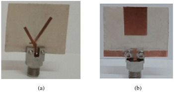
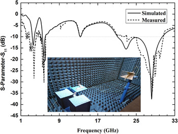
The fabricated triple-band antenna is shown in Fig. 8. The S-parameter (S 11) of the implemented triple-band antenna is shown in Fig. 9 which depicts reasonable agreement between simulated and measured reflection coefficients at all the three operating frequencies with −10 dB impedance bandwidth of 445 MHz (3.225–3.67 GHz) at 3.5 GHz, 657 MHz (5.523–6.180 GHz) at 5.8 GHz, and 5.14 GHz (24.87–30.01 GHz) at 28 GHz.
Fabricated triple-band antenna: (a) front view and (b) rear view.

Simulated and measured S-parameter (S 11) of triple-band antenna.

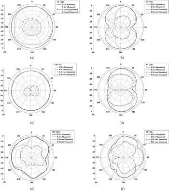
The co and cross radiation patterns in the E and H-plane through computer simulation as well as experiment are shown in Fig. 10. The designed antenna results out closely omnidirectional radiation distribution in the E-plane and bidirectional pattern in H-plane at first two bands (3.5 GHz and 5.8 GHz) as shown in Figs 10(a), (c) and 10(b), (d), respectively, while for 28 GHz, the antenna has a directional radiation pattern in both the planes as shown in Figs 10(e) and 10(f).
Computer-simulated and measured radiation patterns of triple-band antenna.

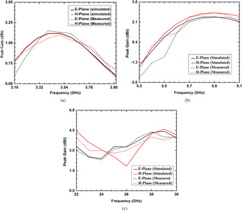
Further, simulated and measured gains over the range of frequencies are shown in Fig. 11. The measured gains are 1.86 dB, 2.55 dB, and 4.41 dB at 3.5 GHz, 5.8 GHz, and 28 GHz, respectively. Figure 12 shows that the simulated radiation efficiency of the proposed dual-band antenna is 95% at 5.8 GHz and 95.2% at 28 GHz, whereas for triple-band antenna the efficiency is 97.8%, 98%, and 97% at 3.5 GHz, 5.8 GHz, and 28 GHz, respectively. The proposed antenna designs are compared in Table 1 with the related studies [Reference Alreshaid, Hussain, Podilchak and Sharawi14, Reference Yassin, Mohamed, Abdallah and El-Hennawy15, Reference Naqvi, Naqvi, Arshad, Riaz, Azam, Khan, Amin, Loo and Tenhunen17] reported in the literature which proves the suitability of the proposed designs for 5G-IoT applications.
Simulated and measured gains of triple-band antenna: (a) 3.5 GHz; (b) 5.8 GHz; and (c) 28 GHz.

Simulated radiation efficiencies of dual- and triple-band antennas.

Comparison with the literature designs

Conclusion
Compact dual-band and triple-band antennas for 5G-IoT applications have been proposed. The dual-band antenna is designed for 5.8 GHz and 28 GHz providing respective impedance bandwidth of 9.65% and 20.2%. The concluding triple-band antenna for 5G-IOT applications operates at 3.5 GHz, 5.8 GHz, and 28 GHz consisting of a printed dipole antenna (for 28 GHz) and two monopole antennas (for 3.5 GHz and 5.8 GHz). The implemented triple-band antenna provides fruitful impedance bandwidth of 12.71%, 11.32%, and 18.3% and high efficiency of 97.8%, 98%, and 97% at 3.5 GHz, 5.8 GHz, and 28 GHz, respectively. From the radiation patterns, it is observed that both the proposed antennas are linearly polarized. The little variance between the simulated and measured results arises because of fabrication and measurement tolerances.
Acknowledgement
The authors thank the reviewers and editors for their valuable suggestions to improve this manuscript. The authors also acknowledge the fruitful discussions with Dr. Debidas Kundu.
 Ruchi received her Master's and Ph.D. in Electronics and Communication Engineering from Thapar University, Patiala, India, in 2012 and 2017, respectively. Currently, she is Post- Doctoral Fellow in the Department of Electronics and Communication Engineering, IIT Roorkee, Roorkee, India. She has more than 7 years of teaching experience in the field of Electronics and Communication Engineering. Her current research includes printed antennas and filtering antennas at microwave and mm-wave frequencies for 4G/5G applications.
 Amalendu Patnaik received his Ph.D. degree in Electronics from Berhampur University in 2003. Prior to joining the Indian Institute of Technology, Roorkee, India, as an Assistant Professor in 2007, he served as a Lecturer at the National Institute of Science and Technology, Berhampur, India. During 2004–05, he was at the University of New Mexico, Albuquerque, USA, as a Visiting Scientist. His current research interest includes RF and microwave engineering, machine-learning applications in electromagnetics, CAD of antennas, and plasmonic antennas. Dr. Patnaik is a senior member of the IEEE. He was awarded the IETE Sir J.C. Bose Award in 1998 and the BOYSCAST Fellowship in 2004–05.
 M. V. Kartikeyan received his M.Sc. in Physics, and Ph.D. in Electronics Engineering from IIT (BHU) Varanasi, Varanasi, India, in 1985 and 1992, respectively. He has been a Full Professor with the Department of Electronics and Communication Engineering, IIT Roorkee, Roorkee, India, since 2009. His current research interests include millimeter/THz wave engineering (electron cyclotron masers, high power devices, and components), metamaterials and fractals, planar microstrip antennas and filters, MICs, and RF and microwave design with soft computing techniques. Prof. Kartikeyan is a Fellow of IEEE, Fellow of the IET (UK), Institution of Electronics and Telecommunications Engineers (India), Institution of Engineers (India), and Vacuum Electronic Devices and Applications Society (India).