Introduction
To fulfill the growing needs of data rates or capacity in a communication environment, ultra-wideband (UWB) technology is intrigued by several researchers. In 2002, the Federal Communication Commission (FCC) assigned an unlicensed band for UWB communication which lies in the frequency range of 3.1–10.6 GHz [1]. Since then, UWB technology faces a lot of challenges such as multi-path fading and bit error rate. To resolve these, multiple-input multiple-output (MIMO) technology has been incorporated which make use of multiple antennas [Reference Kaiser and Zheng2]. It not only enhances the channel capacity of a wireless system without exploiting additional bandwidth, but also helps in mitigating the multi-path fading issues. Over the past few years, a vast amount of literature has been reported on designing a compact UWB-MIMO antenna for wireless communication systems. The major key challenges that one needs to address are antenna's size/dimension, inter-port isolation, impedance bandwidth, and diversity performance. The straightforward approach while accommodating several radiators in a limited-size environment is to separate out all the elements individually and decouple them via spatial distance [Reference Mak, Rowell and Murch3]. In the earlier times, a concept of orthogonal polarization was introduced for UWB-MIMO applications in which multiple antennas are placed perpendicular to each other. However, the overall antenna size also increases along with its inter-port isolation. For attaining compactness in the design, side-by-side arrangement was proposed by many authors but it greatly reduces the isolation between antenna elements [Reference Malviya, Panigrahi and Kartikeyan4, Reference Hui, Zhang, Wang and Zhang5]. Thus, some other isolation techniques were needed to enhance the isolation between radiating elements. Currently, a huge amount of isolation enhancement techniques are available in the literature such as decoupling networks [Reference Wani and Kumar6], electromagnetic band gap (EBG) structures [Reference Wu, Yuan and Wu7, Reference Li, Feresidis, Mavridou and Hall8], neutralization lines [Reference Zhang and Pedersen9], defected ground slots [Reference Kaur, Singh and Upadhyay10, Reference Luo, Hong and Zhong11], and parasitic elements [Reference Khan, Capobianco, Najam, Shoaib, Autizi and Shafique12]. In the mean time, dual-polarized common radiator approach has also been reported for compact UWB-MIMO applications [Reference Mao and Chu13–Reference Khan, Capobianco and Iftikhar15]. However, the isolation between antenna ports is still a major issue but many authors are still trying to fix it. In this connection, a quasi-self-complimentary (QSC) shared-radiator MIMO antenna with tapered-fed for broadband applications is presented and adequate isolation is obtained by modified ground [Reference Patre and Singh16]. Furthermore in [Reference Ghimire, Choi and Choi17], two radiating elements with a shared radiating surface were presented. The high isolation between antenna elements is achieved by etching a circular parasitic element at the center of the ground. Hence, owing to the high isolation and compact structure, the shared-radiator can be a potential candidate for UWB-MIMO wireless applications.
In this paper, a compact dual-polarized co-radiator UWB-MIMO antenna is presented. The top layer of design has a radiator which uses two orthogonal ports for excitation whereas the bottom side comprises of a modified ground plane with an end-loaded line. In this research study, initially a basic circular-patch geometry is selected which is then altered by adding stubs and consequently, its overall combined resonance effects leads to good impedance matching over wide range of frequencies. Furthermore, its inter-port isolation greatly improves with the introduction of end-loaded line into the ground plane. Table 1 highlights the comparison between the proposed antennas with the existing reported articles [Reference Mao and Chu13–Reference Nirmal, Nandgaonkar, Nalbalwar and Gupta19]. Mao et al. [Reference Mao and Chu13], proposed a dual-polarised common radiator for UWB-MIMO applications. Here, the inter-port isolation is maintained by inserting slots in the radiator. Likewise, Srivastava et al. [Reference Srivastava, Kanuijia and Paulus14] investigated UWB-MIMO antenna with high isolation, however, the size is relatively greater than the proposed structure. Then in [Reference Khan, Capobianco and Iftikhar15], a cross-shaped slot is inserted in a shared radiator in order to enhance isolation between ports but the performance of antenna is not adequate because of the asymmetrical configuration. Patre et al. [Reference Patre and Singh16], analyzed a shared radiator MIMO antenna. However, size, impedance bandwidth, and antenna performance require certain improvement to satisfy the modern communication. Recently, Ghimire et al. [Reference Ghimire, Choi and Choi17] designed high-isolated UWB-MIMO antenna with a common radiating surface. The isolation between ports enhanced with a circular parasitic element placed at the backside of the radiator. However, to achieve greater stability in practical wireless communication systems, it is important to consider common ground plane for all the radiating elements. In the mean time, researchers were also applying various other isolation techniques to attain compact high-isolated MIMO antenna. On these linesGorai et al. [Reference Gorai, Dasgupta and Ghatak18] and Nirmal et al. [Reference Nirmal, Nandgaonkar, Nalbalwar and Gupta19] presented compact 2 × 2 UWB-MIMO antenna with enhanced isolation using fractal slots, although their study fulfills the requirement of isolation criteria but their impedance bandwidth is quite lower and also relatively larger footprint than the proposed design. Hence, from the table, one can clearly observe that the proposed antenna is much more simpler and compact which offers much wider impedance bandwidth (3.1 to 16.9 GHz) along with desirable inter-port isolation. Moreover, the proposed antenna also provides dual polarization which can be attained with the orthogonal placement of two vertically polarized antennas [Reference Irene and Rajesh20]. Hence, the signal correlation can be minimized result in quality and reliability of the communication will be increased. Due to its wide operating bandwidth and low correlation, the proposed radiator has the potential to be utilized for wireless personal area communication (WPAN) applications [Reference Mohandoss, Thipparaju, Reddy, Palaniswamy and Marudappa21,Reference Sayginer and Rebeiz22]. The rest of the paper is organized into a section on “Configuration and design of UWB-MIMO antenna,” which contains the antenna configuration and its analysis; section “Results and discussions” discusses the simulated along with its measured results, and finally the proposed MIMO antenna is concluded in section “Analysis of proposed antenna with large ground, USB and housing.”
Comparison of proposed antenna with other antennas

a Isolation is high as the overall size of the proposed structure is larger than the proposed antenna.
b Size of the reported antenna is small; impedance bandwidth is quite lower than the proposed structure.
Configuration and design of UWB-MIMO antenna
Antenna geometry
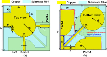
The proposed antenna has three layers namely top layer (radiating element), bottom layer (ground plane), and a middle layer (dielectric substrate). The layouts of the proposed compact co-radiator UWB-MIMO antenna are shown in Fig. 1. The top and bottom layers use copper material whose thickness and conductivity values are 35 μm and 5.96 × 10⁷ S/m, respectively. The middle dielectric layer is made up of FR-4 substrate having relative permeability (ɛ r) equal to 4.4 with loss tangent (tan δ) of 0.02. The proposed antenna is printed on rectangular FR4 substrate with compact size of 29 × 29 mm2 and thickness 0.8 mm. At the top layer, a common radiator is designed by modifying a simple circular patch. The design adds a square-shaped stub and two L-shaped rectangular stubs at its head, as shown in Fig. 1(a). On the other hand, at the bottom side, modified ground plane with a circular end-loaded line is designed. The modified ground comprises of two identical shoe-shaped structures and three rectangular stubs as depicted in Fig. 1(b). The middle diagonal stub is attached to a circular-shaped load at one end and the two rectangular stubs at the other end which is further joined with shoe-shaped structures. A shoe-shaped structure generates an inductive behavior and counterbalances the capacitive effect of radiating element and consequently offers excellent impedance bandwidth. Also, by placing an end-loaded rectangular stub, good isolation between antenna ports has been attained. All the design, simulation and analysis of proposed antenna are carried out using finite integration technique (FIT)-based computer simulation technology microwave studio (CST MWS) [23]. The optimized shape parameters of the proposed antenna are listed as Ls = 29 mm, p 1 = 5 mm, p 2 = 2.25 mm, p 3 = 4.625 mm, p 4 = 9.375 mm, p 5 = 1.524 mm, w = 1.5 mm, g = 1 mm, L = 8.77 mm, Lf = 6 mm, R p = 7.25 mm, g 1 = 26 mm, g 2 = 8.5 mm, g 3 = 10 mm, g 4 = 17.72 mm, g 5 = 7.03 mm, g 6 = 2 mm, g 7 = 1 mm.
(a) Top layout of proposed UWB-MIMO antenna; (b) bottom layout of proposed UWB-MIMO antenna.

Design evolution of proposed antenna
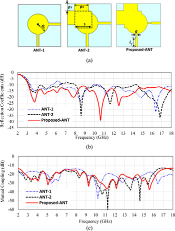
The design strategy of the proposed co-radiator UWB-MIMO antenna and its effect on antenna's desired characteristics is well depicted in Fig. 2. The basic requirement of a UWB antenna for modern portable devices is to attain compact size and operating frequency band defined by FCC, i.e., 3.1−10.6 GHz. In view to this, an appropriate antenna becomes a necessity that is why a monopole structure has been exploited for the development of miniaturized UWB-MIMO system. While analyzing each design step, the bottom part of the proposed antenna (ground) is considered as same for the entire process. Figure 2(a) depicts the evolution process of top radiating patch. Moreover, the effect of each design steps on reflection coefficients and mutual coupling are shown in Figs 2(b) and 2(c), respectively.
(a) Design evolution of proposed co-radiator UWB-MIMO antenna; (b) reflection coefficient comparison for the design steps; (c) mutual coupling comparison for the design steps.

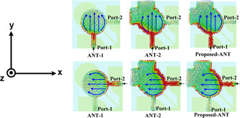
The evolution starts from the conventional circular patch antenna of radius “R p” which is shared by two 50 Ω micro-strip feed lines of width “w.” The concept of shared radiator is used to attain compactness in the antenna design. To illustrate the evolution process of the proposed radiator, surface current distributions at frequency 3.75 GHz corresponding to each design step are analyzed as shown in Fig. 3. As the proposed radiator is identical and symmetrical, therefore both the ports have the same effect on S-parameters. Hence, instead of analyzing the results for both ports, Fig. 3 shows the surface currents when only port-1 is excited whereas port-2 is matched terminated by 50 Ω load. It also noted that the electrical length of the ANT-1 is λ/4 (~23 mm) at 3.3 GHz (lower cut-off frequency) and structure is resonating at 3.3 GHz corresponding to electrical length as depicted in Fig. 2(a). Further, it is clearly verified from surface current distribution that current travels λ/4 distance along the boundary of the radiating element as shown in Fig. 2(c). However, the reflection coefficients (S 11) based on −10 dB covers a certain range of frequencies, i.e., from 3.3 to 5.6 GHz, 6.58 to 9.9 GHz and 10.5 to 18 GHz. Further, to attain lower cut-off frequency and broadband characteristics, another structure ANT-2 is designed by imposing a square of sides “s” and adding two more rectangular stubs over the top head of ANT-1 design. Now, shape of the co-radiator is modified in such a way so that the total electrical length increases results in lower cut-off frequency decreases as shown in Fig. 2(a). The vector current distribution confirms that the electrical length increases due to the modified design as shown in Fig. 3. However, it can be seen from the reflection coefficient plot that a stop band exists over frequencies 6.3−8 GHz. Therefore, the designed radiator is still not covering the entire UWB as defined by FCC (3.1–10.6 GHz). In view to this, several optimizations on the shape parameters and feeding area are performed. Finally, the Proposed-ANT is designed by simply modifying the feed lines in the design of ANT-2. The reflection coefficient plot (Fig. 2(a)) and surface current plot (Fig. 3) show that the impedance matching is achieved by using stepped feed line. Hence, the proposed antenna covers an UWB frequency spectrum from 3.1 to 16.9 GHz which is our intended operating band.
Surface current distributions at 3.75 GHz for each design configuration when one of the port is excited.

Effects of ground plane modification on antenna parameters
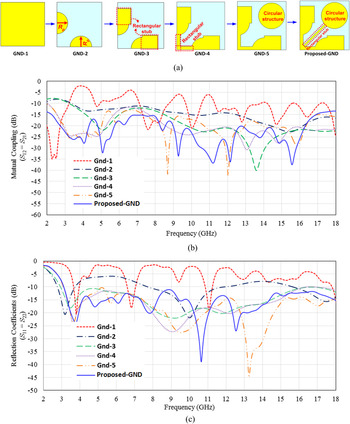
Figure 4(a) shows the evolution of ground plane in the proposed antenna design. To illustrate the effect of ground modification, reflection coefficients (S 11) and mutual coupling (S 12) plots are shown in Figs 4(b) and 4(c), respectively. It is observed that ground plane as GND-1 whose dimensions equals to the overall area of the substrate offers high mismatch in antenna impedance along with poor inter-port isolation over desired frequency of operation. Further, GND-2 has only two similar and symmetrical semi-circular metallic stubs (partial ground) of radius “R p” located just below the feed line. This geometry enhances the impedance bandwidth over frequencies 2.8−3.7 GHz and 7.7−11.9 GHz but inter-port isolation is still poor. In order to attain the desired results, further in GND-3, a rectangular stub of length “g 2” and width “g 3” is added at the center of both semi-circles. This modification shows the dramatic effect on the antenna impedance bandwidth. The structure operates over frequencies 2.9−16 GHz based on −10 dB reflection coefficient but the isolation between elements is still not sufficient as per the standard value used in general wireless communication systems, i.e., −15 dB [Reference Chouhan, Panda, Gupta and Singhal24].
(a) Design steps of the proposed antenna ground plane; (b) effect of ground variation on reflection coefficients; (c) effect of ground variation on mutual coupling.

Therefore, to enhance isolation between shared ports, in GND-4, two rectangular line stubs each having length “g 5” and width “g 6” are used to connect the partial ground of each element. The designed antenna operates over frequencies from 3.1 to 18 GHz with isolation of less than −11.5 dB. In this case, the inter-element isolation is merely improved. Thereafter, in GND-5, a circular structure of radius “R p” is designed just below the shared radiator, which helps in suppressing the unwanted, coupling. In this scenario, the design made no impact on impedance bandwidth but the values of simulated mutual coupling (S 12 = S 21) are well below −13 dB over the entire band of operation, i.e., from 3.1 to 18 GHz. However, the simulated results show that isolation is still not adequate as per the desired value. Finally, the circular structure is joined with the modified ground via another rectangular line stub, which has length “g 4,” and width “g 6.” This increases the effective length of ground plane, which consequently reduces mutual coupling between shared ports. This provides wide impedance bandwidth from 3.1 to 16.9 GHz with better isolation of more than −15 dB over complete operating bands.
Achievement of dual polarization
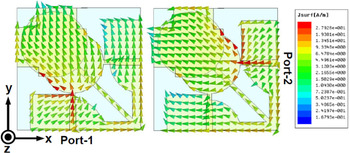
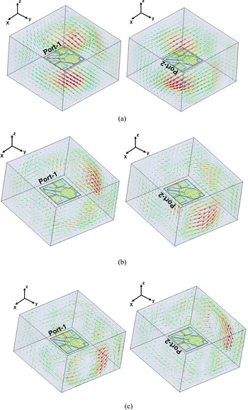
To mitigate multipath fading and improve link reliability of wireless system, concept of dual-polarization has been exploited. Figure 5 shows vector surface current distributions of proposed antenna at 4 GHz when one of the ports is excited. It can be noted that when port-1 is excited, electric current travels mostly in the direction of the y-axis but when port-2 is excited, it shifts along the x-axis which results in horizontal and vertical polarization. Further, Fig. 6 depicts the simulated far-field distributions of electric field at 4, 8 and 12 GHz when both ports of proposed antenna are excited, respectively. It is observed that when port-1 is excited, the electric field is in the direction of the y-axis but when port-2 is excited, it is along the x-axis as shown in Figs 6(a)–6(c) respectively. However, it gets deteriorated at higher frequency and consequently complicates the current distribution observed on the radiator. The orthogonal current analysis aforementioned is consistent with the far-field electric distribution of the proposed antenna and thus exhibiting dual polarization characteristics in the far field [Reference Mao and Chu13–Reference Khan, Capobianco and Iftikhar15]. The dual polarization will provide low correlation in the far-field result in low signal interference can be achieved with the help of proposed UWB MIMO antenna over wide operating band.
Simulated surface current distributions at 4 GHz when both ports are excited.

(a) Simulated far-field distributions of electric field when port-1 and port-2 are excited at 4 GHz; (b) simulated far-field distributions of electric field when port-1 and port-2 are excited at 8 GHz; (c) simulated far-field distributions of electric field when port-1 and port-2 are excited at 12 GHz.

Results and discussions
Parametric ANALYSIS
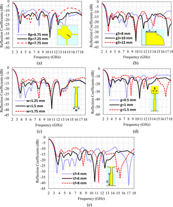
Figure 7 illustrates the variation of reflection coefficients (S 11) with some key parameters of the proposed antenna. Figure 7(a) illustrates the effect of radius “R p” on the reflection coefficient. It is noted that as “R p” is increasing from 6.25 to 7.75 mm, both lower and upper cut-off frequencies are changing due to change in electrical length results in bandwidth and impedance matching are deteriorated. However, “R p” as 7.25 mm is considered as the optimized value to achieve the desired reflection coefficient characteristics. Furthermore, the effect of ground plane parameter “g 3” is analyzed in Fig. 7(b). It is observed that as the value of “g 3” increases or decreases from its optimized value, impedance mismatch deteriorates the reflection coefficients. It chooses g 3 = 10 mm as its optimized design value which provide acceptable return loss (S 11) to cover the desired UWB frequency band. Thereafter, influence of feed width “w” on reflection coefficients is shown in Fig. 7(c). It is noticed that impedance bandwidth at higher frequency is deteriorated as feed width “w” increased. However, when “w” decreases from its optimized value, impedance mismatch around 8–9 GHz deteriorates the overall impedance bandwidth. Therefore, better impedance matching over desired operating band is achieved with feed width “w” as 1.5 mm. Moreover, effect of feed gap “g” is depicted in Fig. 7(d). It is observed that as “g” varies from 0.5 to 1.5 mm, lower and higher cutoff shifts accordingly. The optimized value of feed gap “g” is 1 mm, which ensures good impedance matching over UWB. Likewise, the effect of feed length “L f” is shown in Fig. 7(e). It is clearly noticed that as the length of feed arm increases, lower cut-off resonant frequencies gets towards higher side. After varying “L f” from 4 to 8 mm, better reflection coefficients are obtained with 6 mm.
(a) Effect of radius of patch (R p) on reflection coefficients; (b) effect of width of ground rectangle (g3) on reflection coefficients; (c) effect of width of micro-strip line (w) on reflection coefficients; (d) effect of width of feed line (g) on reflection coefficients; (e) effect of length of the micro-strip feed (L f) on reflection coefficients.

Experimental validation
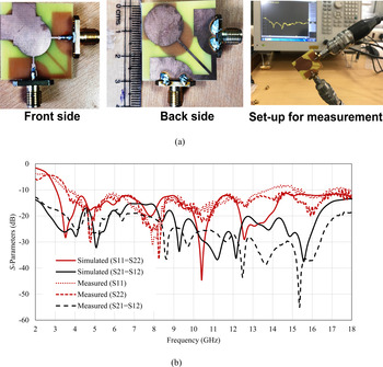
In this section, the experimental validation of simulated results has been discussed. The fabricated prototype of the proposed antenna is shown in Fig. 8(a) and the size is compared on scale. The S-parameters are measured via a Network analyzer [Keysight E5063A (100 kHz–18 GHz)] as shown in Fig. 8(b). Further, in Fig. 8(c), the comparison between simulated and measured S-parameter plots of the proposed antenna is shown. It can be seen that the measured reflection coefficient of Port-1 (S 11) and Port-2 (S 22) are quite different although both structures are mirror images of each other. The difference in the measured reflection coefficient of Port-1 (S 11) and Port-2 (S 22) are mainly due to fabrication inconsistency on both ports. However, both reflection coefficients cover the desired UWB frequency band and closely matching with the simulated one. Likewise, simulated inter-port isolation results are also close to measured mutual coupling. Finally, we conclude that the slight variations in the measured results exist mainly because of the fabrication inaccuracy and experimental errors.
(a) Fabricated prototypes along with measurement set-up; (b) comparison of simulated and measured S-parameters of the proposed antenna.

Radiation performance
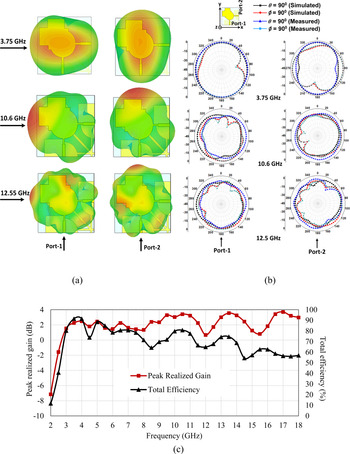
Figure 9(a) and 9(b) shows 3D and 2D far-field radiation patterns of the co-radiator UWB-MIMO antenna at frequencies 3.75, 10.6 and 12.55 GHz. The simulated 3D far-field radiation patterns are obtained using numerical simulator CST MWS as shown in Fig. 9(a). It is noticed that the radiation patterns of each port are orthogonal which will help to mitigate multipath fading and improve the system capacity. In order to validate the 3D simulated radiation pattern, 2D radiation patterns are measured in both vertical plane (ϕ = 900) and horizontal plane (θ = 900). The radiation patterns of the antenna are measured by exciting one port and keeping the other port is matched terminated with a 50 Ω load or vice versa. As the co-radiator is fed by two ports which are positioned orthogonal to each other, so it is evident that their patterns would also be orthogonal. To illustrate it more clearly, 2D far-field radiation patterns at 3.75, 10.6 and 12.55 GHz are measured and plotted in Fig. 9(b). The 2D patterns are also show an orthogonal nature. However, some fabrication and measurement inaccuracy provide mismatch between simulated and measured 2D radiation patterns. Moreover, Fig. 9(c) depicts the peak-realized gain and total antenna efficiency of proposed co-radiator, which reveals that the peak realized gain lies in the range of 0.67−3.55 dBi and its total efficiency varies from 58 to 91% within the same operating band of frequencies.
(a) 3D far-field radiation patterns at 3.75, 10.6 and 12.55 GHz; (b) 2D simulated and measured patterns at 3.75, 10.6 and 12.55 GHz; (c) plots of peak realized gain and total antenna efficiency versus frequency.

Diversity characteristics
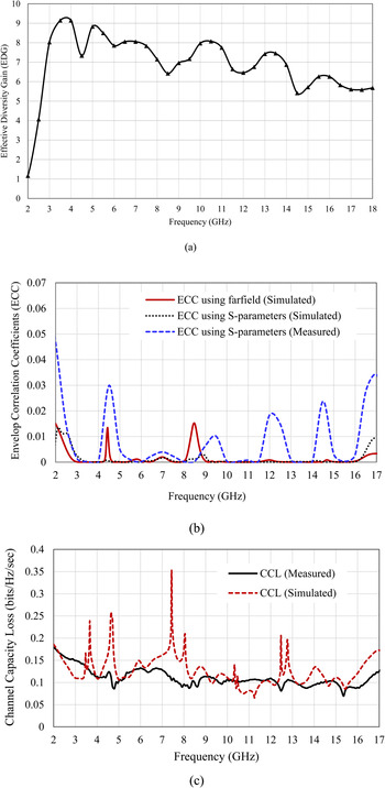
The diversity performance of a MIMO system is evaluated on the basis of diversity parameters such as envelop correlation coefficients (ECC), effective diversity gain (EDG), mean effective gain (MEG). In MIMO systems, ECC indicates the amount of correlation between signals received by the radiator on the same side of the communication channel. The values of ECC can be in the range of [−1, 1] but the desired values should be under 0.5 in order to attain good diversity performance. The mathematical expression to calculate the ECC using far-field data of quad-element MIMO systems are calculated in accordance to the equation mentioned in [Reference Taga25]. DG is another important diversity parameter which gives insight to the effects of diversity on the wireless links. Figure 10(a) highlights the EDG values of the proposed antenna. EDG values are obtained by multiplying DG with total antenna efficiency. Then Fig. 10(b) depicts the comparison between simulated and measured ECC of the proposed antenna. It is observed that both simulated and measured ECC (<0.05) values of the designed antenna are found suitable for UWB-MIMO applications. Likewise, another important figure of merit of a MIMO system is MEG. It quantifies the mean ratio of the received power to the total incident power of each radiating antenna. The analysis has been performed by considering various effects such as radiation power pattern, the wave propagation and its total efficiency. The formula for MEG calculation is given in equation (1) [Reference Taga25, Reference Pedersen, Mogensen and Fleury26]

(a) EDG of the proposed antenna; (b) comparison of simulated and measured ECC; (c) comparison of simulated and measured CCL of the proposed antenna.

The above equation must satisfy the following relations:


where, $G_\theta$ and $G_\phi \;$
 are gain components with respect to angle θ and ϕ. $P_\theta$
 and $P_\phi \;$
 are channel models (the angular density functions of incoming plane waves). As the wireless portable devices move randomly from one place to another, it is evident that the signal can be incident from any of the azimuth direction each having equal probabilities. However, this type of assumption cannot be considered in the direction of elevation plane. The angular density components$\;P_\theta \;$
 and $P_\phi$
 are assumed to be Gaussian in elevation plane and uniform in azimuth plane where the mean and standard deviation is assumed as 10 and 15°, respectively, for both components. MEGs are calculated with different XPR values (0, 5 and 1 dB) for quantifying isotropic, indoor, and outdoor environments, respectively [Reference Pedersen, Mogensen and Fleury26]. Table 2 illustrates MEGs for different XPR at three different frequencies, i.e., 3.75, 10.6, and 12.55 GHz. The ratio of the MEGs of each radiating antenna is approximately equal to unity, which follows the equality criterion of the MIMO system.
MEGs of the proposed UWB MIMO antenna

For MIMO system characterization, channel capacity loss (CCL) of the proposed antenna is calculated which mainly measures the upper threshold level of data rate at which signal is constantly transmitted without incurring noteworthy error. Therefore, the value of channel capacity loss (CCL) should be as low as possible. Mathematically, it is expressed as follows in equation (4) [Reference See, Abd-Alhameed, Abidin, McEwan and Excell27]:

where $\psi ^R = \left[{\matrix{ {\rho_{11}} & {\rho_{12}} \cr {\rho_{21}} & {\rho_{22}} \cr } } \right]$ is the correlation matrix and ρ ij are the elements of ψ R matrix. The values of all the elements are computed from S-parameters, as given in the below equation:

where i and j are the indices of S-parameters. Figure 10(c) shows measured and simulated CCL curves of the proposed shared UWB-MIMO antenna. The expected CCL values should lie under 0.4 bps/Hz. The plot reveals that both the simulated and measured values of CCL are quite less than that of the expected CCL values over the operating range of frequencies, which leads to stable MIMO characteristics.
Analysis of proposed antenna with large ground, USB and housing
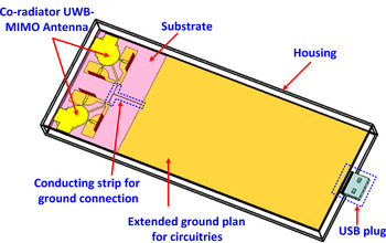
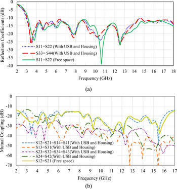
In this section, the simulation study of antenna performance when it is installed on PCB with a USB connector and device housing is reported. Figure 11 shows the four-element co-radiator UWB-MIMO antenna with extended ground, a USB port and housing. In practice, the size of ground plane is never considered as a design freedom but only design team of the wireless device decides it. Hence, in a practical scenario where multiple antennas are embedded onto a portable gadget, the printed circuit board (PCB) will be served as a large ground. Here PCB size is taken as 144 × 73 mm2, which is inter-connected via T-shaped strip to the proposed antenna. The area of horizontal and vertical thin conducting strips is 13.2 × 0.125 and 20.3 × 0.125 mm2, respectively. The reason for using such small strips is to minimize the effects of large PCB serving as a ground plane. Each component of the designed circuitry is placed inside the housing of size 196 × 77 mm2. The housing is created from plastic box, which has dielectric constant of 3.4, and loss tangent of 0.001 and its thickness is taken as 1 mm. At the opposite extreme of the antenna, a USB plug is designed which makes sense for practical application. The overall dimension of USB connector is 12 × 15 × 3.75 mm3. The outer part of USB is made up of perfect metallic covering in which four perfect electric conducting strips (12 × 1 mm2) are integrated on Plexiglass of thickness of 1.875 mm. Figure 12 depicts the simulated S-parameters of the proposed antenna in actual communication environment and free space. It shows that impedance matching slightly improved at lower frequency band and the low cut-off frequencies for S 11 ≤ −10 dB shifts toward the lower side without disturbing the operating bands.
Four-element UWB-MIMO antennas with extended ground, a USB port and housing.

(a) Comparison of reflection coefficients in actual environment (attached with USB and housing) with free space; (b) comparison of mutual coupling between antenna elements in actual environment (attached with USB and housing) with free space.

It is also noted that the isolation between shared ports (S 12 = S 21 = S 34 = S 43) has almost negligible effect on antenna's behavior which is well below −15 dB over operating bands, whereas the isolation between other ports (S 24 = S 42) and (S 13 = S 31) is less than −13 and −20 dB, respectively, which is found within the limit. From the results, it can be clearly seen that the effect of PCB, USB connector and housing on the performance of proposed antenna is almost insignificant; this makes it a suitable candidate for wireless UWB-MIMO applications.
Conclusion
In this study, a compact co-radiator antenna is investigated for UWB-MIMO applications. The impedance matching of under −10 dB is achieved over frequencies 3.1−16.9 GHz. In addition to this, satisfactory level of isolation, i.e., −15 dB is obtained over the wide frequency of operation. The inter-port isolation is improved due to an end-loaded line, which could be further improved via applying various isolation enhancement techniques. The simulated and measured results of the proposed antenna well agree with each other and the diversity parameters, i.e., EDG, ECC, CCL, and ratio of MEGs also lie within the acceptable limit. Further, the proposed antenna is investigated by placing in actual scenario of portable devices like housing, USB connectors and large ground plane. The reflection coefficient and mutual coupling as well as below the desired limit, which makes the designed antenna well suitable for modern portable devices.
Acknowledgements
The authors acknowledge the Department of Electronics and Communication Engineering, TIET, Patiala, Punjab for providing necessary instrument facility to carry out the measurement and also acknowledge Thapar Institute of Engineering and Technology, Patiala, Punjab for providing seed money grant as financial support to carry out this research study. Further, authors also acknowledge M/s HAMA IoT Solutions Private Limited, Sonbhadra, Uttar Pradesh (incubated at TIDES, IIT Roorkee under the scheme of DST NIDHI PRAYAS Project) for financial support to carry out this study.
 Harleen Kaur received her B.Tech degree in electronics and communication engineering in 2014 from Lovely Professional University, Jalandhar, India. M.E. in wireless communication engineering with specialization in speech signal processing in 2017 from Thapar University, Patiala, India. She is currently pursuing Ph.D. in ultra-wideband MIMO antennas for wireless applications at Thapar Institute of Engineering and Technology, Patiala, India. She has published two papers in reputed international conferences. Her research interests include designing of compact ultra-wideband MIMO antennas for modern portable wireless communication devices, ultra-wideband MIMO antennas with band-notched characteristics, reducing the mutual coupling between radiating elements and meta-material inspired antennas for multiband operation in wireless systems.
 Hari Shankar Singh was born in Sonbhadra (U.P.), India, in 1990. He received his B.Tech. degree from the IEC College of Engineering and Technology, Greater Noida (U.P.), India, in 2011 and Ph.D. degree from the Department of Electronics Engineering, Indian Institute of Technology (Banaras Hindu University), Varanasi, India, in 2015. Currently, he is working as assistant professor in the Department of Electronics and Communication Engineering, Thapar Institute of Engineering and Technology, Patiala, Punjab, India. His Ph.D. thesis has been awarded “Best Ph.D. Thesis” in the 3rd IEEE UPCON 2016 conference, held in IIT (BHU), Varanasi from December 09 to 11, 2016. He has published 34 research papers in refereed International Journals and more than 42 research papers published/presented in national and international conferences/ symposium/ workshops. His research interests include microstrip antenna, MIMO antenna systems, ultrawideband (UWB) antennas, electromagnetic bandgap (EBG) structure, RFID antennas, mobile antenna, and multiple antennas-user interactions. He has published more than 45 papers in various peer-reviewied international journals and conferences. He serves as a referee for various referred journals.
 Rahul Upadhyay received his engineering degree in electronics and communication engineering from Rajiv Gandhi Technical University, Bhopal, India, and Ph.D. degree in signal processing from the Indian Institute of Information Technology, Jabalpur, India, in 2009 and 2016, respectively. Since late 2016, he has been working as assistant professor, Department of Electronics and Communication Engineering, Thapar Institute of Engineering and Technology, Patiala, India. His research interests include biomedical signal and image processing, soft computing techniques and brain computer interface.