1. Introduction
Many applications involve small solid bodies (also further termed particles) suspended in a viscous fluid bounded by some surfaces. For dilute suspensions one can ignore particle–particle interactions and focus on the interactions of a single particle with one close surface. For a small enough particle the analysis can be achieved within the framework of low-Reynolds-number (Stokes) flow for which the inertial effects can be neglected. There is a huge body of literature devoted to Stokes flows about one or a collection of solid particles immersed in a bounded or unbounded viscous Newtonian fluid (see e.g. Happel & Brenner Reference Happel and Brenner1973; Kim & Karrila Reference Kim and Karrila1991). Such works mostly address the Stokes flow about a no-slip solid particle interacting with a plane no-slip wall and consider the case of the body experiencing a given rigid-body motion in a quiescent fluid (so-called resistance problem) and/or the case of the body suspended (held fixed or free to move) in a prescribed ambient linear shear flow. Far from the wall the solution can be obtained using Lamb’s general solution (Lamb Reference Lamb1932) for a spherical particle and by resorting to the boundary-integral approach with the free-space Green velocity tensor (see Ladyzhenskaya Reference Ladyzhenskaya1963) for arbitrary particles and ambient Stokes flows. This latter procedure was first implemented by Youngren & Acrivos (Reference Youngren and Acrivos1975) for spheroids and a given ambient linear shear flow. It has been further extended to take into account of the wall by using (Lorentz Reference Lorentz1907; Blake Reference Blake1971) the velocity Green tensor complying there with the no-slip condition. In this direction one can, for instance, refer to Hsu & Ganatos (Reference Hsu and Ganatos1989) for the resistance problem of a body of revolution, Gavze & Shapiro (Reference Gavze and Shapiro1997), Mody & King (Reference Mody and King2005) and Pozrikidis (Reference Pozrikidis2005) who considered spheroids and a linear shear flow and Hsu & Ganatos (Reference Hsu and Ganatos1989) and Mitchell & Spagnolie (Reference Mitchell and Spagnolie2015) for the settling of a spheroid. When the wall–particle gap normalised with the particle length scale becomes very small the boundary-integral method becomes very computationally intensive and its accuracy deteriorates. The semi-analytical bipolar coordinates technique is free from those drawbacks but solely applies for a spherical particle interacting with a flat boundary. When carefully implemented it provides very accurate results even for a very small normalised wall–sphere gap. The case of a sphere moving near the wall in a quiescent fluid has been considered in Brenner (Reference Brenner1961), Dean & O’Neill (Reference Dean and O’Neill1963), Maud (Reference Maud1963), O’Neill (Reference O’Neill1964) and Goldman & Cox (Reference Goldman and Cox1967a ). For a sphere suspended in a given ambient flow one can refer to Goldman & Cox (Reference Goldman and Cox1967b ) and Chaoui & Feuillebois (Reference Chaoui and Feuillebois2003) for the linear shear flow and Pasol et al. (Reference Pasol, Sellier and Feuillebois2006, Reference Pasol, Sellier and Feuillebois2009) for the modulated and quadratic shear flows.
For some basic applications (especially at the microscale) the fluid (liquid or gas) is allowed to slip tangent to some impermeable surfaces. There the previous no-slip boundary condition breaks down and needs to be replaced with another relevant slip condition. The choice of the slip condition is of the utmost importance since it directly drives and affects the fluid flow. One simple and linear model is the famous Navier (Reference Navier1823) slip condition proposed for a fluid flowing in the
 $x_3\gt 0$
domain above a motionless and impermeable solid wall
 $\varSigma$
located at
 $x_3=0$
. On that flat surface, having unit normal
 $\boldsymbol {n},$
the fluid velocity
 $\boldsymbol{u}$
is subject to the usual impermeability condition and a so-called Navier slip condition bearing on the tangent velocity
 $\boldsymbol {u}_t=\boldsymbol {u}-(\boldsymbol {u}\boldsymbol{\cdot }\boldsymbol {n})\boldsymbol {n}.$
Those conditions are
 \begin{equation} \boldsymbol {u}\boldsymbol{\cdot }\boldsymbol {n}=0\quad\text{and}\quad \boldsymbol {u}_t=\lambda {\partial {\boldsymbol {u}_t}\over {\partial x_3}}\quad\text{on }\varSigma ,\end{equation}
where
 $\lambda \geqslant 0$
is the wall slip length characterising the ability of the plane to let the fluid flow tangent to it. Of course, the usual no-slip condition is retrieved for
 $\lambda =0.$
In practice, the slip length depends on both the nature of the wall and the fluid. Its experimental and/or theoretical (see e.g. Lecoq et al. Reference Lecoq, Anthore, Cichocki, Szymczak and Feuillebois2004) determination is a key tricky issue not addressed in the present work which considers
 $\lambda$
to be given. Although the above Navier slip condition is linear and quite old, it has received in past decades several experimental confirmations and was also considered in microfluidics (see Stone, Stroock & Adjari Reference Stone, Stroock and Adjari2004). For a rarefied gas (Maxwell Reference Maxwell1879) the slip length reads
 $\lambda =(2-\sigma ){\ell }_m/\sigma$
with
 ${\ell }_m$
the gas mean free path and
 $\sigma$
the surface tangential momentum accommodation coefficient which is the fraction of molecules experiencing a diffusive (in contrast to specular) reflection on the solid surface. In practice,
 $\sigma$
is in the range
 $[0,1]$
and for small
 $\sigma$
the slip length can be large compared with
 ${\ell }_m.$
Depending on the solid surface, a liquid can admit different slippage behaviours experimentally observed using several techniques (reviewed in detail in Lauga, Brenner & Stone (Reference Lauga, Brenner and Stone2007)) for various systems. For instance (Churaev & Sobolev Reference Churaev, Sobolev and Somov1984), one induces a pressure-driven flow in a circular capillary, with radius
 $R,$
measures the flow rate
 $Q(\lambda )$
and deduces the slip length as
 $\lambda =[Q(\lambda )/Q(\lambda =0)-1](R/4).$
A different drainage experiment imposes a squeezing flow between two close approaching surfaces (of the same nature) and measures the occurring resistive drainage force either with (Baudry et al. Reference Baudry, Charlaix, Tonck and Mazuyer2001; Cottin-Bizonne et al. Reference Cottin-Bizonne, Jurine, Baudry, Crassous, Restagno and Charlaix2002) a surface force apparatus or with (Vinogradova & Yakubov Reference Vinogradova and Yakubov2003) an atomic force apparatus. A theoretical lubrication model relating the force to the equal slip on the surfaces is then used to deduce the slip length
 $\lambda .$
Both previous approaches are global (indirect) ones and other local methods are also used. These methods measure the velocity of a pressure-driven flow between two parallel plane walls and afford
 $\lambda$
by fitting with the theoretical velocity profile. For instance, in Joseph & Tabeling (Reference Joseph and Tabeling2005) particle image velocimetry is employed. The experiences reveal that when the liquid wets the surface (there called a hydrophilic surface) there is no slip. In contrast, a slip is measured when the liquid is not wetting the surface which is termed a hydrophobic surface. In practice, a surface can be hydrophobised by a chemical treatment so that it becomes repellent to the considered liquid. For some patterned hydrophobised surfaces the value of
 $\lambda$
can reach about
 $10$
μm and the surface is termed superhydrophobic (Rothstein Reference Rothstein2010; Vinogradova & Dubov Reference Vinogradova and Dubov2012). In such cases for a micrometric particle, with typical length
 $a,$
one can have
 $\lambda /a\geqslant O(1).$
This remark actually also holds for a rarefied gas, especially at low pressure. Finally, note that the no-shear free-surface case is retrieved in the limit
 $\lambda /a\gg 1.$
Accordingly, in the present work we consider
 $\lambda$
to be prescribed and put no restriction on the magnitude of
 $\lambda /a.$
While introduced for a plane motionless surface by Navier (Reference Navier1823), the slip condition has been extended to curved moving surfaces. For example, the resistance problem for a slip sphere, with a Navier slip, moving in a quiescent unbounded fluid is solved in Basset (Reference Basset1961). At a curved surface
 $\varSigma _c,$
with unit normal
 $\boldsymbol {n}$
pointing into the Newtonian fluid, one expresses the generalised Navier condition in terms of the stress applied by the flow on that surface. More precisely, for a flow with velocity
 $\boldsymbol {u}$
and stress tensor
 $\boldsymbol{\sigma }$
, the extension of (1.1) is
 \begin{equation} \boldsymbol {u}\boldsymbol{\cdot }\boldsymbol {n}=0\,\text{and}\,\boldsymbol {u}_t=\lambda [\boldsymbol{\sigma }\boldsymbol{\cdot }\boldsymbol {n}- (\boldsymbol {n}\boldsymbol{\cdot }{\boldsymbol \sigma }\boldsymbol{\cdot }\boldsymbol {n})\boldsymbol {n}]/\mu \,\text{on } {\varSigma _c}, \end{equation}
where
 $\mu$
denotes the uniform fluid shear viscosity. The case of a solid non-slip sphere interacting with a slip plane wall is handled, using bipolar coordinates, in O’Neill & Bhatt (Reference O’Neill and Bhatt1991) for a quiescent fluid, in Davis, Kezirian & Brenner (Reference Davis, Kezirian and Brenner1994) and Loussaief, Pasol & Feuillebois (Reference Loussaief, Pasol and Feuillebois2015) for ambient linear shear flow and in Ghalia, Feuillebois & Sellier (Reference Ghalia, Feuillebois and Sellier2016) for ambient quadratic shear flow. The case of a slip sphere translating normal to a slip plane wall is treated by appealing to bipolar coordinates in Goren (Reference Goren1973) and Reed & Morrison (Reference Reed and Morrison1974) and for a small normalised wall–sphere gap by a lubrication analysis in Hocking (Reference Hocking1973) and Vinogradova (Reference Vinogradova1995). Except for Hocking (Reference Hocking1973), the previously mentioned papers allow different slip lengths on the sphere and the plane wall. A boundary-integral method is employed in Luo & Pozrikidis (Reference Luo and Pozrikidis2008) for a slip sphere interacting with a plane slip wall when immersed in a quiescent fluid or a shear flow. This is achieved using the free-space Green velocity tensor (and thus by meshing both the sphere surface and the wall) although Lauga & Squires (Reference Lauga and Squires2005) and Elasmi (Reference Elasmi2008) provided earlier the Green velocity tensor complying with the Navier slip on the wall. Finally, very few papers deal with a non-spherical particle interacting with a plane slip wall. For instance, Vinogradova (Reference Vinogradova1996; Reference Vinogradova1999) deal, by a lubrication analysis, with some non-spherical slip particles translating normal to a very close plane slip wall. Moreover, the resistance problem for a no-slip and nearly spherical ellipsoid interacting with a slip plane wall is treated in Feuillebois, Ghalya & Sellier (Reference Feuillebois, Ghalya and Sellier2012) by a boundary-integral method using a convenient form of the velocity Green tensor ensuring the Navier slip on the wall and therefore only meshing the particle surface. Only small non-sphericity effects have been reported in Feuillebois et al. (Reference Feuillebois, Ghalya and Sellier2012) because the considered ellipsoid is nearly spherical and is not inclined. It is thus of interest to investigate non-sphericity and orientation effects for other no-slip bodies both for the resistance problem and for particle rigid-body migration when it is freely suspended in a prescribed ambient Stokes flow. The present work addresses these issues.
The rest of this paper is organised as follows. In § 2 the governing equations and the problems for a particle moving in a quiescent fluid (resistance problem) or migrating when freely suspended in a given ambient Stokes flow are presented together with six key auxiliary Stokes flows. The advocated boundary formulation, which permits one to reduce the task to the treatment of six boundary-integral equations on the particle surface, is given in § 3. Also in § 3, a ‘recipe’ connecting, for a slip small compared with the wall–particle gap, the results for the slip wall and for another shifted no-slip wall is established for the resistance problem and the case of ambient ‘linear’ and quadratic shear flows. The numerical implementation is detailed and benchmarked in § 4. Then, § 4 reports and discusses the numerical results obtained for a family of inclined non-spheroidal ellipsoids, having the same volume, either moving in a quiescent fluid or migrating when freely suspended in a given ambient ‘linear’ or quadratic shear flow. Finally, § 5 contains some concluding remarks.
2. Governing problems for a solid body interacting with a plane slip wall
This section presents the governing Stokes problems for a solid and arbitrarily shaped no-slip body suspended in a given arbitrary ambient Stokes flow, of a Newtonian fluid, near a plane, solid, motionless and impermeable slip wall. It also introduces useful auxiliary flows and the associated surface stresses on the particle boundary.
2.1. Governing equations and challenging cases
Consider, as shown in figure 1, a solid and arbitrarily shaped no-slip body
 $\mathcal P$
(also termed particle) immersed in a Newtonian fluid bounded by a solid, motionless, impermeable and plane slip wall
 $\varSigma .$
A solid, arbitrarily shaped and no-slip particle
 ${\mathcal P},$
with length scale
 $a,$
immersed in a Newtonian liquid near the
 $x_3=0$
motionless, impermeable and slipping plane wall
 $\varSigma .$
The particle–wall gap is
 $d$
, the wall slip length is
 $\lambda$
and M designates a point located in the
 $ x_{3}\gt 0$
domain. The particle is suspended in a prescribed ambient flow
 $(\boldsymbol {u}_a,p_a)$
and its rigid-body motion has translational velocity
 $\boldsymbol {U}$
and angular velocity
 ${\boldsymbol \varOmega }.$
For example, the velocity profile of a ‘linear’ ambient shear flow is drawn for
 $\lambda \gt 0.$

The particle length scale is
 $a$
and the wall–particle gap is
 $d\gt 0.$
Note that this work therefore disregards the case of a particle in contact with the wall.
We use Cartesian coordinates
 $(O,x_1, x_2, x_3),$
with origin
 $O$
attached to the
 $x_3=0$
plane wall
 $\varSigma$
and associated unit vectors
 $(\boldsymbol {e}_1, \boldsymbol {e}_2, \boldsymbol {e}_3).$
Thus, a point M located in the
 $x_{3}\gt 0$
domain (see figure 1) is located with
 $ \boldsymbol {x}=\boldsymbol{O \kern-2pt M}$
and one has
 $x_{i}=\boldsymbol {x}\boldsymbol{\cdot }\boldsymbol {e}_{i}.$
The fluid uniform density is
 $\rho_{\kern-1pt f}$
and its viscosity is
 $\mu \gt 0.$
Far from the particle a prescribed arbitrary ambient steady Stokes flow, with velocity
 $\boldsymbol {u}_a$
and pressure
 $p_a,$
might be imposed. This ambient flow satisfies the Stokes equations together with appropriate boundary conditions on the impermeable slip wall
 $\varSigma .$
More precisely,
 \begin{align} \mu {\boldsymbol{\nabla} }^2\boldsymbol {u}_a &={\boldsymbol{\nabla }\!}p_a\,\text{and}\,{\boldsymbol{\nabla }}\boldsymbol{\cdot }\boldsymbol {u}_a=0 \text{ for }{ x_3\gt 0,} \end{align}
 \begin{align} \boldsymbol {u}_a\boldsymbol{\cdot }\boldsymbol {e} _3 &=0\,\text{and}\,\boldsymbol {u}_a\boldsymbol{\cdot }\boldsymbol {e}_{\!j}=\lambda \left[{{\partial \boldsymbol {u}_a\boldsymbol{\cdot }\boldsymbol {e}_{\!j}}\over {\partial x_3}}\right]\, {\text{for } j=1,2 \text{ on } \varSigma (x_3=0).} \end{align}
As discussed in the introduction, the second condition (2.2) is the Navier (Reference Navier1823) slip condition on the wall with slip length
 $\lambda \geqslant 0.$
For example, an ambient shear flow with velocity
 $\boldsymbol {u}_a=[k_l(x_3+\lambda )+k_q x_3^2]\boldsymbol {e}_1$
and pressure
 $p_a=2\mu k_q x_3$
satisfies (2.1)–(2.2). It has parameters
 $k_l$
and
 $k_q$
associated with a ‘linear’ and a quadratic shear flow, respectively.
As shown in figure 1, the particle rigid-body motion has translational velocity
 $\boldsymbol {U}$
(here the velocity of the point
 $O'$
attached to the particle) and angular velocity
 ${\boldsymbol \varOmega }.$
The particle affects the ambient flow so that the flow about the particle has velocity
 $\boldsymbol {u}_a+\boldsymbol {u}$
and pressure
 $p_a+p$
in the fluid domain
 ${\mathcal D}.$
The flow Reynolds number is
 $ {Re}=\rho_{\kern-1pt f} V a/\mu$
with
 $a$
the particle length scale and
 $V$
the typical magnitude of
 $\boldsymbol {u}_a+\boldsymbol {u}.$
Assuming that
 $ {Re}\ll 1$
ensures that, like
 $(\boldsymbol {u}_a,p_a),$
the flow
 $(\boldsymbol {u},p)$
satisfies the steady Stokes equations. The particle surface
 $S$
is no-slip and the flow
 $(\boldsymbol {u},p)$
therefore obeys
 \begin{align} \mu {\boldsymbol{\nabla} }^2\boldsymbol {u}&={\boldsymbol{\nabla }}p\,\text{and}\,{\boldsymbol{\nabla }}\boldsymbol{\cdot }\boldsymbol {u}=0\quad\text{in }{\mathcal D},\, (\boldsymbol {u},p)\rightarrow (\boldsymbol {0},0)\,\text{as}\,|\boldsymbol{O \kern-2pt M}|\rightarrow \infty , \end{align}
 \begin{align} \boldsymbol {u}\boldsymbol{\cdot }\boldsymbol {e}_3&=0\,\text{and}\,\boldsymbol {u}\boldsymbol{\cdot }\boldsymbol {e}_{\!j}=\lambda \left[{{\partial \boldsymbol {u}\boldsymbol{\cdot }\boldsymbol {e}_{\!j}}\over {\partial x_3}}\right]\, {\text{for } j=1,2 \text{ on } \varSigma (x_3=0),} \end{align}
 \begin{align} \boldsymbol {u}&=-\boldsymbol {u}_a+\boldsymbol {U}+{\boldsymbol\varOmega }\wedge \boldsymbol{O}'\!\boldsymbol{M}\,\text{on }S. \end{align}
The flow
 $(\boldsymbol {u},p)$
has stress tensor
 ${\boldsymbol \sigma }.$
It exerts on the particle boundary
 $S,$
having unit normal
 $\boldsymbol {n}$
pointing into the fluid, a surface stress
 $\boldsymbol {f}={\boldsymbol \sigma }\boldsymbol{\cdot }\boldsymbol {n}.$
Likewise, the ambient flow field
 $(\boldsymbol {u}_a,p_a)$
with stress tensor
 ${{\boldsymbol \sigma }\!}_a$
induces on
 $S$
a stress
 $\boldsymbol {f\!}_a={{\boldsymbol \sigma }\!}_a\boldsymbol{\cdot }\boldsymbol {n}.$
Since (2.1) also holds inside the particle, integrating
 $\boldsymbol {f\!}_a$
and its first moment on
 $S$
yields zero force and torque on the particle. Accordingly, the force
 $\boldsymbol {F}$
and the torque
 $\boldsymbol\varGamma$
(about the point
 $O')$
exerted by the flow
 $(\boldsymbol {u}_a+\boldsymbol {u},p_a+p)$
on the particle can be written
 \begin{equation} \boldsymbol {F}=\int _S {\boldsymbol \sigma }\boldsymbol{\cdot }\boldsymbol {n}{\rm d}S,\,{\boldsymbol\varGamma }=\int _S \boldsymbol{O}'\!\boldsymbol{M}\wedge {\boldsymbol \sigma }\boldsymbol{\cdot }\boldsymbol {n}{\rm d}S. \end{equation}
The problem (2.3)–(2.5) is linear in both the ambient flow
 $(\boldsymbol {u}_a,p_a)$
and the particle rigid-body motion
 $(\boldsymbol {U},{\boldsymbol \varOmega }).$
Therefore, it is possible to distinguish three different cases.
Case 1 is for a particle moving with a given rigid-body motion
 $(\boldsymbol {U},{\boldsymbol \varOmega })$
in a quiescent liquid, i.e. for
 $(\boldsymbol {u}_a,p_a)=(\boldsymbol {0},0).$
By linearity, the hydrodynamic force
 $\boldsymbol {F}_{\!h}$
and torque
 ${\boldsymbol\varGamma }_h$
experienced by the particle are written
 $\boldsymbol {F}_{\!h}=-\mu \{\boldsymbol {A}\boldsymbol{\cdot }\boldsymbol {U}+\boldsymbol {B}\boldsymbol{\cdot }{\boldsymbol \varOmega }\}$
and
 ${\boldsymbol\varGamma }_h=-\mu \{\boldsymbol {C}\boldsymbol{\cdot }\boldsymbol {U}+\boldsymbol {D}\boldsymbol{\cdot }{\boldsymbol \varOmega }\}$
with so-called resistance second-rank tensors
 $\boldsymbol {A}, \boldsymbol {B}, \boldsymbol {C}$
and
 $\boldsymbol {D}$
depending upon the wall slip length
 $\lambda$
and the particle geometry and location.
Case 2 is for a particle held fixed
 $(\boldsymbol {U}={\boldsymbol \varOmega }=\boldsymbol {0})$
in the ambient flow. As shown in § 2.2, both the force
 $\boldsymbol {F}_{\!a}$
and the torque
 ${\boldsymbol\varGamma }_a$
exerted on the particle can be obtained by solely solving the previous Case 1.
Case 3 is for a particle freely suspended in the ambient flow. Combining the previous Cases 1 and 2 gives
 $\boldsymbol {F}=\boldsymbol {F}_{\!h}+\boldsymbol {F}_{\!a}$
and
 ${\boldsymbol\varGamma }={\boldsymbol\varGamma }_h+{\boldsymbol\varGamma }_a.$
Imposing the freely suspended particle to be force-free and torque-free provides its rigid-body motion
 $(\boldsymbol {U},{\boldsymbol \varOmega })$
by solving the linear equations
 $\mu \{\boldsymbol {A}\boldsymbol{\cdot }\boldsymbol {U}+\boldsymbol {B}\boldsymbol{\cdot }{\boldsymbol \varOmega }\}=\boldsymbol {F}_{\!a}$
and
 $\mu \{\boldsymbol {C}\boldsymbol{\cdot }\boldsymbol {U}+\boldsymbol {D}\boldsymbol{\cdot }{\boldsymbol \varOmega }\}={\boldsymbol\varGamma }_a.$
The stress
 $\boldsymbol {f\!}_a+\boldsymbol {f}$
on the particle surface
 $S$
is subsequently obtained in two steps: first, by calculating
 $\boldsymbol {f\!}_a={{\boldsymbol \sigma }\!}_a\boldsymbol{\cdot }\boldsymbol {n}$
and then getting the flow
 $(\boldsymbol {u},p)$
solution to (2.3)–(2.5) for the rigid-body motion
 $(\boldsymbol {U},{\boldsymbol \varOmega })$
to obtain its traction
 $\boldsymbol {f}={\boldsymbol \sigma } \boldsymbol{\cdot }\boldsymbol {n}$
. This stress
 $\boldsymbol {f\!}_a+\boldsymbol {f}$
can in practice be obtained by solving a boundary-integral equation (see (3.4)). Once known, it permits one to calculate the second-rank symmetric stresslet tensor
 $\boldsymbol {S}$
defined as (since the particle is force-free the definition of
 $\boldsymbol {S}$
is independent of the selected point
 $O^\prime$
)
 \begin{equation} \boldsymbol {S}={{1}\over {2}}\int _S\biggl \{\boldsymbol{O}'\!\boldsymbol{M} \otimes (\boldsymbol {f\!}_a+\boldsymbol {f})+ (\boldsymbol {f\!}_a+\boldsymbol {f})\otimes \boldsymbol{O}'\!\boldsymbol{M}-{{2}\over {3}} \big[(\boldsymbol {f\!}_a+\boldsymbol {f})\boldsymbol{\cdot }\boldsymbol{O}'\!\boldsymbol{M} \big]\boldsymbol {I} \biggl \}{\rm d}S \end{equation}
with
 $\boldsymbol {I}$
the identity tensor. For instance, the component
 $S_{13}=\boldsymbol {e}_1\boldsymbol{\cdot }\boldsymbol {S}\boldsymbol{\cdot }\boldsymbol {e}_3$
is the essential ingredient in the calculation of the effective viscosity of a dilute suspension of particles subject to ambient ‘linear’ shear flow either for an unbounded suspension (see Batchelor Reference Batchelor1970; Batchelor & Green Reference Batchelor and Green1972a
,Reference Batchelor and Green
b
) or, as shown in Tözeren & Skalak (Reference Tözeren and Skalak1983), for a suspension bounded by a no-slip plane wall.
2.2. Extended reciprocal identity and resulting well-posed linear system
This subsection extends for a fluid bounded by the plane slip wall
 $\varSigma$
the usual material available in standard textbooks (see Happel & Brenner Reference Happel and Brenner1973; Kim & Karrila Reference Kim and Karrila1991) for the unbounded fluid case. Consider two flow fields
 $(\boldsymbol {u},p)$
and
 $(\boldsymbol {u}',p')$
obeying (2.3). Let their stress tensors be
 $\boldsymbol \sigma$
and
 ${\boldsymbol \sigma }',$
respectively. Mimicking the treatment given in Happel & Brenner (Reference Happel and Brenner1973) for the unbounded fluid, then easily yields
 \begin{equation} \int _{S\cup \varSigma }[\boldsymbol {u}\boldsymbol{\cdot }{\boldsymbol \sigma }'\boldsymbol{\cdot }\boldsymbol {n}-\boldsymbol {u}'\boldsymbol{\cdot }{\boldsymbol \sigma }\boldsymbol{\cdot }\boldsymbol {n}]{\rm d}S=0,\, \int _{S\cup \varSigma }\boldsymbol {u}\boldsymbol{\cdot }{\boldsymbol \sigma }\boldsymbol{\cdot }\boldsymbol {n}{\rm d}S=-2\mu \int _{{\mathcal D}}e_{\textit{ij}}e_{\textit{ij}}{\rm d}\varOmega \end{equation}
with
 $\mathcal D$
the liquid domain. In (2.8) there is a summation over indices
 $i$
and
 $j$
(taking the values 1, 2, 3) and
 $e_{\textit{ij}}$
designates the Cartesian component of the flow second-rank rate of strain tensor
 $\boldsymbol {e}.$
Hence, setting
 $u_i=\boldsymbol {u}\boldsymbol{\cdot }\boldsymbol {e}_i$
and
 $u_{i,j}=\partial u_i/\partial x_{\!j}$
gives
 $e_{\textit{ij}}=(u_{i,j}+u_{j,i})/2.$
Requiring both
 $\boldsymbol {u}$
and
 $\boldsymbol {u}'$
to satisfy the Navier boundary conditions (2.4) on the
 $x_3=0$
slip wall
 $\varSigma$
also yields (recall, see figure 1, that
 $\boldsymbol {n}=\boldsymbol {e}_3$
and also that
 $u_{3,j}=u_3=u^{\prime}_{3,j}=u^{\prime}_3=0$
for
 $j=1,2$
on
 $\varSigma $
)
 \begin{align} \boldsymbol {u}\boldsymbol{\cdot }{\boldsymbol \sigma }'\boldsymbol{\cdot }\boldsymbol {n}&=\lambda \mu \left(u_{1,3}u^{\prime}_{1,3}+u_{2,3}u^{\prime}_{2,3}\right)=\boldsymbol {u}'\boldsymbol{\cdot }{\boldsymbol \sigma }\boldsymbol{\cdot }\boldsymbol {n} \,\text{and} \nonumber\\ \boldsymbol {u}\boldsymbol{\cdot }{\boldsymbol \sigma }'\boldsymbol{\cdot }\boldsymbol {n}&=\lambda \mu \big\{(u_{1,3})^2+(u_{2,3})^2\big\}\, {\text{on } \varSigma .} \end{align}
According to (2.8)–(2.9) two arbitrary flows
 $(\boldsymbol {u},p)$
and
 $(\boldsymbol {u}',p')$
fulfilling (2.3)–(2.4) satisfy, whatever the wall slip length
 $\lambda \geqslant 0,$
the key identities and inequality
 \begin{align} \int _S\boldsymbol {u}\boldsymbol{\cdot }{\boldsymbol \sigma }'\boldsymbol{\cdot }\boldsymbol {n}{\rm d}S&=\int _S\boldsymbol {u}'\boldsymbol{\cdot }{\boldsymbol \sigma }\boldsymbol{\cdot }\boldsymbol {n}{\rm d}S, \end{align}
 \begin{align} E_S:= \int _S\boldsymbol {u}\boldsymbol{\cdot }{\boldsymbol \sigma }\boldsymbol{\cdot }\boldsymbol {n}{\rm d}S&=-\mu \left [2\int _{{\mathcal D}}e_{\textit{ij}}e_{\textit{ij}}{\rm d}\varOmega +\lambda \int _{\varSigma }\big\{(u_{1,3})^2+(u_{2,3})^2\big\}{\rm d}S \right ]\lt 0.\\[9pt] \nonumber \end{align}
The result (2.10) is an extension of the Lorentz reciprocity theorem for two arbitrary flows
 $(\boldsymbol {u},p)$
and
 $(\boldsymbol {u}',p')$
bounded by the slip wall
 $\varSigma .$
The equality (2.11) expresses the rate of energy dissipation,
 $E_S,$
of the surface stress
 $\boldsymbol {f}={\boldsymbol \sigma }\boldsymbol{\cdot }\boldsymbol {n}$
on the particle boundary
 $S.$
The inequality
 $E_S\lt 0$
is valid whatever the wall slip length
 $\lambda \geqslant 0$
and the flow
 $(\boldsymbol {u},p)$
obeying (2.3)–(2.4) (of course, we actually discard the quiescent fluid case for which
 $E_S=0$
).
In dealing with Case 1 let us introduce for
 ${i}=1,2,3$
six auxiliary flows
 $(\boldsymbol {u}^{(i)}_t, p^{(i)}_t)$
and
 $(\boldsymbol {u}^{(i)}_r, p^{(i)}_r)$
obeying (2.3)–(2.4) and the boundary conditions
 $\boldsymbol {u}^{(i)}_t=\boldsymbol {e}_i$
and
 $\boldsymbol {u}^{(i)}_r=\boldsymbol {e}_i\wedge \boldsymbol{O}'\!\boldsymbol{M}$
on the particle surface
 $S.$
These flows are induced by a translation or a rotation of the particle in quiescent fluid. For
 $L=t,r$
the flow
 $(\boldsymbol {u}^{(i)}_L, p^{(i)}_L)$
has stress tensor
 ${\boldsymbol \sigma }^{(i)}_L$
and exerts on
 $S$
a stress
 $\boldsymbol {f}^{(i)}_L={\boldsymbol \sigma }^{(i)}_L\boldsymbol{\cdot }\boldsymbol {n}.$
The Cartesian components
 $A_{\textit{ij}}, B_{\textit{ij}}, C_{\textit{ij}}$
and
 $D_{\textit{ij}}$
of the resistance tensors
 $\boldsymbol {A}, \boldsymbol {B}, \boldsymbol {C}$
and
 $\boldsymbol {D}$
introduced in § 2.1 are then expressed as
 \begin{align} A_{\textit{ij}}&=-{\frac {1}{\mu }}\left[\int _S\boldsymbol {e}_i\boldsymbol{\cdot }\boldsymbol {f}^{(j)}_t {\rm d}S\right]\!,\, B_{\textit{ij}}=-{\frac {1}{\mu }}\left[\int _S\boldsymbol {e}_i\boldsymbol{\cdot }\boldsymbol {f}^{(j)}_r {\rm d}S\right]\!, \end{align}
 \begin{align} C_{\textit{ij}}&=-{\frac {1}{\mu }}\left[\int _S\boldsymbol {e}_i\boldsymbol{\cdot }\left(\boldsymbol{O}'\!\boldsymbol{M}\wedge \boldsymbol {f}^{(j)}_t\right){\rm d}S\right]\!,\, D_{\textit{ij}}=-{\frac {1}{\mu }}\left[\int _S\boldsymbol {e}_i\boldsymbol{\cdot }\left(\boldsymbol{O}'\!\boldsymbol{M}\wedge \boldsymbol {f}^{(j)}_r\right){\rm d}S\right]\!. \end{align}
In Case 2, the particle held fixed in the ambient flow
 $(\boldsymbol {u}_a,p_a)$
experiences a force
 $\boldsymbol {F}_{\!a}$
and a torque
 ${\boldsymbol\varGamma }_a.$
These vectors are obtained by applying the reciprocal identity (2.10) to the perturbed flow
 $(\boldsymbol {u},p)$
about the fixed particle and the flows
 $(\boldsymbol {u}^{(i)}_L, p^{(i)}_L).$
Adopting henceforth the usual summation convention over repeated indices then gives
 \begin{equation} \boldsymbol {F}_{\!a}=-\left[\int _S\boldsymbol {u}_a\boldsymbol{\cdot }\boldsymbol {f}^{(i)}_t {\rm d}S\right]\boldsymbol {e}_i,\, {\boldsymbol\varGamma }_a=-\left[\int _S\boldsymbol {u}_a\boldsymbol{\cdot }\boldsymbol {f}^{(i)}_r {\rm d}S\right]\boldsymbol {e}_i. \end{equation}
Accordingly, the Cartesian components
 $\boldsymbol {U}=U_{\!j}\boldsymbol {e}_{\!j}$
and
 ${\boldsymbol \varOmega }=\varOmega _{\!j}\boldsymbol {e}_{\!j}$
of the freely suspended particle translational and angular velocities satisfy for
 $i=1,2,3$
the equations
 \begin{equation} \mu \big\{A_{\textit{ij}}U_{\!j}+B_{\textit{ij}}\varOmega _{\!j} \big\}=\int _S\boldsymbol {u}_a.\boldsymbol {f}^{(i)}_t {\rm d}S,\, \mu \big\{C_{\textit{ij}}U_{\!j}+D_{\textit{ij}}\varOmega _{\!j} \big\}=\int _S\boldsymbol {u}_a.\boldsymbol {f}^{(i)}_r {\rm d}S. \end{equation}
The linear system (2.15) is written
 $\boldsymbol {R}\boldsymbol{\cdot }{(}^t\!\boldsymbol{X}{)}=\boldsymbol {Y}$
with
 $^t\!\boldsymbol{X}$
the transpose of
 $\boldsymbol {X}=(\boldsymbol {U},{\boldsymbol \varOmega })$
and
 $\boldsymbol {R}$
the so-called
 $6\times 6$
resistance matrix. Applying (2.12)–(2.13) and the reciprocal identity (2.10) gives
 $A_{\textit{ij}}=A_{ji},\ B_{\textit{ij}}=C_{ji}$
and
 $D_{\textit{ij}}=D_{ji}$
so that
 $\boldsymbol {R}$
is symmetric. Moreover, from (2.11) one gets
 $E_S=-\mu \boldsymbol {X}\boldsymbol{\cdot }\boldsymbol {R}\boldsymbol{\cdot }{(}^t\!\boldsymbol{X}{)}\lt 0$
whatever the non-zero particle rigid-body motion
 $\boldsymbol {X}.$
Thus,
 $\boldsymbol {R}$
is positive-definite. Consequently, the linear system (2.15) has a unique solution
 $(\boldsymbol {U},{\boldsymbol \varOmega }).$
3. Boundary-integral method and resulting asymptotic results
This section describes in § 3.1 the boundary-integral approach employed to solve Cases 1–3. The required Green tensor is presented in § 3.2 and asymptotic results for a particle–wall gap
 $d$
that is large compared with the wall slip length
 $\lambda$
are displayed in § 3.3.
3.1. Boundary-integral approach
The flow
 $(\boldsymbol {u},p),$
solution to (2.3)–(2.5), is obtained by a boundary-integral method. This is done by extending the material presented for a no-slip wall in Pozrikidis (Reference Pozrikidis1992). The main results are given while, since elementary, the proofs are left to the reader.
Consider for
 $j=1,2,3$
the fundamental Stokes flow produced, above the slip wall and in the absence of the particle, by a force with strength
 $\boldsymbol {e}_{\!j}$
concentrated at a source point
 $\boldsymbol {y}$
located in the
 $y_3\gt 0$
domain. The flow velocity
 $\boldsymbol {v}^{(j)}(\boldsymbol {x},\boldsymbol {y})$
and pressure
 $p^{(j)}(\boldsymbol {x},\boldsymbol {y})$
at any point
 $\boldsymbol {x}$
above the wall
 $(x_3\geqslant 0)$
satisfy
 \begin{align} \mu {\boldsymbol{\nabla} }^2\boldsymbol {v}^{(j)}&={\boldsymbol{\nabla }}p^{(k)}-\delta _{3d}(\boldsymbol {x}-\boldsymbol {y})\boldsymbol {e}_k,\!\!\quad\! {\boldsymbol{\nabla }}\boldsymbol{\cdot }\boldsymbol {v}^{(j)}=0,\!\!\quad \big(\boldsymbol {u}^{(j)},p^{(j)}\big)\rightarrow (\boldsymbol {0},0)\!\!\!\quad\text{as }|\boldsymbol{O \kern-2pt M}|\rightarrow \infty , \end{align}
 \begin{align} \boldsymbol {v}^{(j)}\boldsymbol{\cdot }\boldsymbol {e}_3&=0\,{\text {and}}\,\boldsymbol {v}^{(j)}\boldsymbol{\cdot }\boldsymbol {e}_i= \lambda \left[{{\partial \boldsymbol {v}^{(j)}\boldsymbol{\cdot }\boldsymbol {e}_i}\over {\partial x_3}}\right]\, {\text{for } i=1,2 \text{ on } \varSigma (x_3=0),} \end{align}
with
 $\delta _{3d}(\boldsymbol {x}-\boldsymbol {y})=\delta _d(x_1-y_1)\delta _d(x_2-y_2)\delta _d(x_3-y_3)$
and
 $\delta _d$
the Dirac distribution. Solving (3.1)–(3.2) provides the second-rank velocity tensor
 $\boldsymbol {G}(\boldsymbol {x},\boldsymbol {y})$
with Cartesian components
 $G_{\textit{ij}}(\boldsymbol {x},\boldsymbol {y})=8\pi \mu \boldsymbol {v}^{(j)}(\boldsymbol {x},\boldsymbol {y})\boldsymbol{\cdot }\boldsymbol {e}_i.$
Proceeding as in Pozrikidis (Reference Pozrikidis1992) and using again the reciprocal identity (2.10) yields the symmetry property
 $G_{\textit{ij}}(\boldsymbol {x},\boldsymbol {y})=G_{ji}(\boldsymbol {y},\boldsymbol {x})$
and a single-layer integral representation, over the particle surface
 $S$
and in the entire fluid domain
 ${\mathcal D},$
for each velocity component
 $u_{\!j}=\boldsymbol {u}\boldsymbol{\cdot }\boldsymbol {e}_{\!j}$
of the flow
 $(\boldsymbol {u},p)$
solution to (2.3)–(2.5). It reads (summing over indices
 $i$
in (3.3))
 \begin{equation} u_{\!j}(\boldsymbol {x})=-{{1}\over {8\pi \mu }}\int _S G_{ji}(\boldsymbol {x},\boldsymbol {y})[\boldsymbol {f\!}_a+\boldsymbol {f}](\boldsymbol {y})\boldsymbol{\cdot }\boldsymbol {e}_i{\rm d}S\, {\text{for}\, \boldsymbol {x}\in {\mathcal D}\, \text{and}\, j=1,2,3.} \end{equation}
For (3.3) recall that
 $\boldsymbol {f\!}_a$
and
 $\boldsymbol {f}$
are the surface stresses induced on
 $S$
by the ambient flow
 $(\boldsymbol {u}_a,p_a)$
and the perturbation flow
 $(\boldsymbol {u},p).$
Actually, (3.3) still holds as
 $\boldsymbol {x}$
tends onto
 $S.$
Imposing (2.5) then yields the following boundary-integral equation:
 \begin{equation} 8\pi \mu \big[\boldsymbol {u}_a(\boldsymbol {x})-\boldsymbol {U}-{\boldsymbol\varOmega }\wedge \boldsymbol{O}'\!\boldsymbol{M} \big]= \int _S \boldsymbol {G}(\boldsymbol {x},\boldsymbol {y})\boldsymbol{\cdot }[\boldsymbol {f\!}_a+\boldsymbol {f}](\boldsymbol {y}){\rm d}S\, {\text{for } \boldsymbol {x} \text{ on } S} \end{equation}
for the stress
 $\boldsymbol {f\!}_a+\boldsymbol {f}$
exerted on the particle boundary.
The boundary-integral equation (3.4) is of the first kind. Usually, integral equations of the first kind can be ill-posed. Here, the solution
 $\boldsymbol {f\!}_a +\boldsymbol {f}$
to (3.4) is defined up to a constant multiple of
 $\boldsymbol {n}$
which, however, does not affect the resistance matrix Cartesian components (2.12)–(2.13) and the force
 $\boldsymbol {F}_{\!a}$
and torque
 ${\boldsymbol\varGamma }_a$
given by (2.14). Despite this property, Youngren & Acrivos (Reference Youngren and Acrivos1975) found for an unbounded fluid that the numerical treatment of (3.4) provides accurate solutions and stated that ‘very accurate solutions were obtained with minimal difficulty, a fact which suggests that any ill-conditioning that may exist is much less serious for this particular equation than for other integral equations of the first kind’. The same nice behaviour has been observed in the present work for (3.4). As detailed in § 4.2, accurate results have been obtained nicely agreeing with the literature which resorts to quite different approaches. In this work the particle surface
 $S$
is meshed using six-node curved boundary elements and this enables us to accurately invert (3.4) spreading on
 $S$
a reasonable number of nodal points and therefore ending up with a well-conditioned matrix for the linear system resulting from discretising (3.4). It is also theoretically possible to start from a velocity integral representation different from (3.3) and termed compound double-layer representation (see Pozrikidis Reference Pozrikidis1992). This approach, pioneered in Power & Miranda (Reference Power and Miranda1987), ends up with a well-posed boundary-integral equation of the second kind replacing (3.4). Unfortunately, it requires calculation of the third-rank stress tensor
 $\boldsymbol {T}$
associated with the problem second-rank Green velocity tensor
G
given in § 3.2. Since the determination of
 $\boldsymbol {T}$
is very cumbersome, such a procedure is not worked out in this work.
From the (numerical) knowledge of the stress
 $\boldsymbol {f\!}_a+\boldsymbol {f}$
it is possible to subsequently compute in the fluid domain
 $\mathcal D$
the flow velocity
u
by implementing the integral representation (3.3). Similarly, the pressure
 $p$
associated with
u
also admits a useful integral representation in the fluid domain. This representation requires the determination of the fundamental pressure
 $p^{(k)}$
for the problem (3.1)–(3.2) and is not provided here.
All Cases 1–3 presented in § 1.2 are solved using (3.4). First, the surface stresses
 $\boldsymbol {f}^{(i)}_t$
and
 $\boldsymbol {f}^{(i)}_r$
are obtained by inverting (3.4) for
 $\boldsymbol {u}_a=\boldsymbol {0}.$
Then, the resistance tensors
 $\boldsymbol {A}, \boldsymbol {B}, \boldsymbol {C}$
and
 $\boldsymbol {D}$
follow from (2.11)–(2.12) and
 $(\boldsymbol {F}_{\!a},{\boldsymbol\varGamma }_a)$
for Case 2 is deduced from (2.14). The linear system (2.15) is solved to get the freely suspended particle rigid-body motion
 $(\boldsymbol {U},{\boldsymbol \varOmega }).$
Finally, inverting (3.4) provides the stress
 $\boldsymbol {f\!}_a+\boldsymbol {f}$
and thereby the components of the stresslet tensor defined by (2.7).
3.2. Green tensor
The Green tensor
 $\boldsymbol {G}$
was obtained in different forms in Lauga & Squires (Reference Lauga and Squires2005) and Elasmi (Reference Elasmi2008). However, these forms are not convenient for a numerical purpose and this perhaps explains why Lauga & Squires (Reference Lauga and Squires2005) did not perform any computation of
 $\boldsymbol {G}$
. Here,
 $\boldsymbol {G}$
is thus provided in another closed form which is quite appropriate for an efficient numerical treatment.
In the absence of a wall,
 $\boldsymbol {G}$
is the free-space Stokeslet tensor
 $ \boldsymbol {G}^{st}$
given by Lorentz (Reference Lorentz1907). It reads
 \begin{equation} \boldsymbol {G}^{st}(\boldsymbol {x},\boldsymbol {y})=\boldsymbol {I}/|\boldsymbol {x}-\boldsymbol {y}|+ (\boldsymbol {x}-\boldsymbol {y})\otimes (\boldsymbol {x}-\boldsymbol {y})/|\boldsymbol {x}-\boldsymbol {y}|^3 \end{equation}
with
 $\boldsymbol {I}=\boldsymbol {e}_i\otimes \boldsymbol {e}_i$
the usual unit tensor. Following the approach of Blake (Reference Blake1971) for the no-slip wall case,
 $\boldsymbol {G}$
is sought as
 $\boldsymbol {G}(\boldsymbol {x},\boldsymbol {y})=\boldsymbol {G}^{st}(\boldsymbol {x},\boldsymbol {y}) -\boldsymbol {G}^{st}(\boldsymbol {x},\boldsymbol {y}')+\boldsymbol {W}(\boldsymbol {x},\boldsymbol {y})$
, where
 $\boldsymbol {y}'$
denotes the symmetric (image point) of
 $\boldsymbol {y}$
with respect to the slip wall
 $\varSigma$
at
 $x_3=0.$
The tensor
 $\boldsymbol {W},$
which is regular in the entire domain above the wall, is obtained by applying a two-dimensional Fourier transform on the variables
 $x_1-y_1$
and
 $x_2-y_2.$
Such a technique has been also worked out in Sellier & Ghalya (Reference Sellier and Ghalya2011) for the more complex case of anisotropic Navier slip on a plane wall. Here, the Cartesian components
 $W_{\textit{ij}}(\boldsymbol {x},\boldsymbol {y})$
are expressed in terms of seven one-dimensional Hankel integrals. The results are
 $(\text{taking}\, i=1,2)$
 \begin{align} W_{i3}(\boldsymbol {x},\boldsymbol {y})&={{2y_3(x_i-y_i)}\over {\rho }} \left[L_1^{1,1}-x_3L_1^{2,1}\right];\quad W_{33}(\boldsymbol {x},\boldsymbol {y})=-2x_3 y_3 L_1^{2,0}, \end{align}
 \begin{align} W_{11}(\boldsymbol {x},\boldsymbol {y})&=2[x_3 y_3+2\lambda (x_3+y_3)] \biggl \{\left({{x_1-y_1}\over {\rho }}\right)^2 L_1^{2,2}-{{L_1^{1,1}}\over {\rho }}\biggr \}\nonumber \\ &\quad +4\lambda ^2\biggl \{{{L_2^{1,1}}\over {\rho }} -\left({{x_2-y_2}\over {\rho }}\right)^2 L_2^{2,2}\biggr \}+4\lambda L_1^{1,0}, \end{align}
 \begin{align} W_{21}(\boldsymbol {x},\boldsymbol {y})&={{2(x_1-y_1)(x_2-y_2)}\over {\rho ^2}} \Big \{[x_3 y_3+2\lambda (x_3+y_3)]L_1^{2,2}+ 4\lambda ^2 L_2^{2,2}\Big \}, \end{align}
 \begin{align} W_{31}(\boldsymbol {x},\boldsymbol {y})&={{2(x_1-y_1)}\over {\rho }} \biggl \{x_3(y_3+2\lambda )L_1^{2,1} +{{\rho y_3}\over {\big(\rho ^2+R_3^{\prime 2}\big)^{3/2}}}\biggr \} \end{align}
with
 $R^{\prime}_3=x_3+y_3,\ \rho =\{(x_1-y_1)^2+(x_2-y_2)^2\}^{1/2}$
and Hankel integrals
 $L_1^{p,q}$
and
 $L_2^{p,q}$
defined in terms of
 $(\rho ,R^{\prime}_3;\lambda )$
in Appendix A. Moreover,
 $W_{12}=W_{21}$
while
 $W_{22}$
and
 $W_{32}$
are obtained therefrom by switching
 $x_1-y_1$
and
 $x_2-y_2$
in (3.7) and (3.9), respectively. For
 $\lambda =0$
each of the above Hankel integrals can be analytically obtained and one retrieves the Blake (Reference Blake1971) tensor derived for a no-slip plane wall. As
 $\rho \rightarrow 0$
, each above quantity
 ${W}_{\!\textit{ij}}(\boldsymbol {x},\boldsymbol {y})$
tends to a finite value given in Appendix A.
3.3. Resulting asymptotic results
For a particle–wall gap
 $d$
(see figure 1) that is large compared with the wall slip length
 $\lambda ,$
one expects to retrieve, at leading order, the case of the particle interacting with a no-slip wall located at
 $x_3={-\lambda }.$
Obtaining a more refined approximation, versus the small parameter
 $\epsilon =\lambda /d,$
requires additional effort. This can be done, within the previous boundary-integral formulation, by asymptotically expanding the Green tensor
 $\boldsymbol {G}(\boldsymbol {x},\boldsymbol {y})$
for points
 $\boldsymbol {x}$
and
 $\boldsymbol {y}$
located on the particle surface using the property
 $\text{Min}(x_3,y_3)\geqslant d\gg \lambda .$
Note that in addition to the lengths
 $d$
and
 $\lambda ,$
the particle length scale
 $a$
also arises in the problem.
For a particle that is distant from the slip wall, in the sense
 $d\gg a$
and
 $\lambda \leqslant O(a),$
it is possible to use the asymptotic results derived in Khabthani, Sellier & Feuillebois (Reference Khabthani, Sellier and Feuillebois2013) for a particle distant from a porous slab with thickness
 $e,$
permeability
 $K\gt 0$
and upper and lower plane surfaces on which Beavers & Joseph (Reference Beavers and Joseph1967) boundary conditions with slip length
 $\lambda$
apply. The associated Green tensor, obtained in Khabthani et al. (Reference Khabthani, Sellier, Elasmi and Feuillebois2012), is complicated and depends upon
 $(\sqrt {K}, e, \lambda ).$
It reduces to the present Green tensor
 $\boldsymbol {G}$
for vanishing
 $\sqrt {K}.$
Denoting by
 $\boldsymbol {G}^{\textit{ns}}$
the Blake (Reference Blake1971) Green tensor for a no-slip wall
 $\varSigma$
at
 $x_3=0$
(i.e. obtained by taking
 $\lambda =0$
in § 3.2) and letting
 $\sqrt {K}$
vanish in (35)–(36) from Khabthani et al. (Reference Khabthani, Sellier and Feuillebois2013) easily yields
 \begin{equation} \boldsymbol {G}(\boldsymbol {x},\boldsymbol {y})=\boldsymbol {G}^{\textit{ns}}(\boldsymbol {x},\boldsymbol {y})\big[1+O\big(a^2/d^2\big)\big]\quad {\text{for } \boldsymbol {x} \text{ and } \boldsymbol {y} \text{ on } S \text{ and } 0\leqslant \lambda \leqslant O(a)\ll d.} \end{equation}
As worked out in Khabthani et al. (Reference Khabthani, Sellier and Feuillebois2013) for a distant sphere, (3.10) can be used to derive an asymptotic solution of (3.4) for a distant and arbitrary-shaped particle. However, (3.10) only holds for
 $d\gg O(a)$
although the case
 $d\leqslant O(a)$
can also occur when
 $\lambda \leqslant O(a)\ll d.$
The case
 $\lambda \ll d$
has been treated by Lecoq et al. (Reference Lecoq, Anthore, Cichocki, Szymczak and Feuillebois2004) at the first order in
 $\epsilon =\lambda /\text{Min}(a,d)\ll 1$
and only for a sphere translating normal to the plane slip wall. The drag experienced by the sphere for the slip wall with sphere–wall gap
 $d$
is shown by those authors to be, at
 $O \big(\epsilon ^2 \big),$
the same as for a no-slip wall with sphere–wall gap
 $d+\lambda .$
Another approach is developed here to extend these results to non-spherical particles and/or other rigid-body motions. It consists of expanding for points
 $\boldsymbol {x}$
and
 $\boldsymbol {y}$
on the particle surface
 $S$
the Green tensor
 $\boldsymbol {G}(\boldsymbol {x},\boldsymbol {y})$
given in § 3.2 for
 $\epsilon =\lambda /d\ll 1.$
Indeed, introducing shifted points
 $\boldsymbol{\tilde {x}}=\boldsymbol {x}+\lambda \boldsymbol {e}_3$
and
 $\boldsymbol{\tilde {y}}=\boldsymbol {y}+\lambda \boldsymbol {e}_3$
shown in figure 2 and noting that
 $x_3\geqslant d\gg \lambda$
and
 $y_3\geqslant d\gg \lambda$
, it is found (see e.g. Appendix B for the component
 $G_{31})$
that
 \begin{equation} \boldsymbol {G}(\boldsymbol {x},\boldsymbol {y})=\boldsymbol {G}^{\textit{ns}}(\boldsymbol{\tilde {x}},\boldsymbol{\tilde {y}})\big[1+O \big(\epsilon ^2 \big)\big]\quad {\text{for } \boldsymbol {x} \text{ and } \boldsymbol {y} \text{ on } S \text{ and } \epsilon =\lambda /d\ll 1.} \end{equation}
In contrast to (3.10), the expansion (3.11) brings no restriction on the normalised particle distance
 $d/a$
from the slip wall and no restriction on the normalised wall slip length
 $\lambda /a.$
Clearly, the tensor
 $\boldsymbol {G}^{\textit{ns}}(\boldsymbol{\tilde {x}},\boldsymbol{\tilde {y}})$
is that for a particle interacting with a no-slip wall
 $\varSigma$
that is shifted normally to the actual wall so that the new particle–wall gap is
 ${\tilde d}=d+\lambda .$
The different cases associated with
 $\boldsymbol {G}(\boldsymbol {x},\boldsymbol {y})$
and
 $\boldsymbol {G}^{\textit{ns}}(\boldsymbol{\tilde {x}},\boldsymbol{\tilde {y}})$
are sketched in figure 2.
The same particle interacting with a plane wall in two different circumstances. (a) Case of a wall–particle gap
 $d$
and a slip wall
 $\varSigma$
with slip length
 $\lambda \ll d.$
(b) Case of wall–particle gap
 ${\tilde d}=d+\lambda$
and a no-slip wall. For this figure,
 $d$
is of the same order as the particle length scale
 $a.$

At a point
 $M$
on the particle surface
 $S$
the key auxiliary stress
 $\boldsymbol {f}^{(i)}_L$
depends upon
 $S,$
the wall–particle gap
 $d,$
the wall slip length
 $\lambda$
and the location
 $\boldsymbol {x}'=\boldsymbol{O}'\!\boldsymbol{M}.$
Given a particle and omitting the dependence on
 $S,$
we note
 $\boldsymbol {f}^{(i)}_L(\boldsymbol {x}';d,\lambda )$
for the previous stress and
 $\boldsymbol {R}(d,\lambda )$
for the resulting resistance matrix introduced in § 2.2. Using (3.11) and asymptotically inverting for
 $\boldsymbol {u}_a=\boldsymbol {0}$
the boundary-integral equation (3.4), versus
 $\epsilon =\lambda /d\ll 1,$
then yields
 \begin{align} \boldsymbol {f}^{(i)}_L(\boldsymbol {x}';d,\lambda )=\boldsymbol {f}^{(i)}_L(\boldsymbol {x}';d+\lambda ,0)\big[1+O \big(\epsilon ^2 \big)\big], \!\!\quad\boldsymbol {R}(d,\lambda )=\boldsymbol {R}(d+\lambda ,0)\big[1+O \big(\epsilon ^2 \big)\big]. \\[-20pt] \nonumber \end{align}
The results (3.12), extending those of Lecoq et al. (Reference Lecoq, Anthore, Cichocki, Szymczak and Feuillebois2004) to any rigid-body motion of a particle with arbitrary shape, provide a ‘recipe’ for
 $\epsilon =\lambda /d\ll 1$
: one can, at
 $O \big(\epsilon ^2 \big),$
replace the slip wall located at
 $d$
from the particle with a no-slip wall located at
 $d+\lambda .$
Clearly, this ‘recipe’ also holds for the settling motion of the particle under a given gravity field in the absence of ambient flow. In contrast, the ‘recipe’ is not always valid for a particle freely suspended in a given ambient flow. This feature is illustrated by considering two examples of ambient shear flows.
(i) Ambient ‘unit linear’ shear flow with velocity
 ${\boldsymbol{\tilde u}}_a^l=(x_3+\lambda )\boldsymbol {e}_1.$
For this flow the particle experiences a force
 ${\boldsymbol{\tilde F}}_a^l(d,\lambda )$
and a torque
 ${\boldsymbol{\tilde \varGamma }}_a^l(d,\lambda )$
when it is held fixed and translational velocity
 ${\tilde U}^l(d,\lambda )$
and angular velocity
 $\tilde {\boldsymbol \varOmega }^l(d,\lambda )$
when it is freely suspended. As sketched in figure 2, for figure 2(a) the slip wall is located at a distance
 $d$
from the particle and for figure 2(b) the wall is no-slip and located at a distance
 $d+\lambda$
. For each case (2.14) is applied. Noting that in figure 2(b) the ambient velocity is
 ${\tilde x}_3\boldsymbol {e}_1$
with
 ${\tilde x}_3=x_3+\lambda$
and recalling (3.12) immediately gives
 \begin{equation} {\boldsymbol{\tilde V}}^l(d,\lambda )={\boldsymbol{\tilde V}}^l(d+\lambda ,0)\big[1+O \big(\epsilon ^2 \big)\big],\quad {\boldsymbol{\tilde V}}={\boldsymbol{\tilde F}}_a, {\boldsymbol{\tilde \varGamma }}_a, {\boldsymbol{\tilde U}}, \tilde {{\boldsymbol \varOmega }}. \end{equation}
Thus, the ‘recipe’ is valid for the ambient ‘linear’ shear flow.
(ii) Ambient ‘unit’ quadratic shear flow with velocity
 ${\tilde u}_a^l=x_3^2\boldsymbol {e}_1.$
Here, the notations for the force, torque and velocities are the same as before with the superscript
 $l$
replaced with
 $q.$
For the case of figure 2(b) note that on the particle surface
 $x_3\geqslant d\gg \lambda$
so that
 ${\tilde x}_3^2\sim x_3^2+2\lambda {\tilde x}_3.$
Consequently,
 \begin{equation} {\boldsymbol{\tilde V}}^q(d,\lambda )=\big[{\boldsymbol{\tilde V}}^q-2\lambda {\boldsymbol{\tilde V}}^l\big](d+\lambda ,0)\big[1+O \big(\epsilon ^2 \big)\big],\quad {\boldsymbol{\tilde V}}={\boldsymbol{\tilde F}}_a, {\boldsymbol{\tilde \varGamma }}_a, {\boldsymbol{\tilde U}}, \tilde {{\boldsymbol \varOmega }}. \end{equation}
According to (3.14) the ‘recipe’ is not valid for the ambient quadratic shear flow.
4. Numerical results for some ellipsoidal particles
This section examines to what extent the hydrodynamic interactions between the particle and the slip wall depend on the wall slip length, the particle (shape and location) and the ambient ‘linear’ or quadratic shear flow. This is carried out here by considering some ellipsoidal particles having identical volume but different semi-axes and orientations.
4.1. Considered ellipsoidal particles and resulting normalised quantities
Consider, as shown in figure 3(a), a solid ellipsoid with planes of symmetry intersecting at its centre of volume
 $O',$
normal to the unit vectors
 ${\tilde {\boldsymbol {e}}}_1, {\tilde {\boldsymbol {e}}}_2$
and
 ${\tilde {\boldsymbol {e}}}_3$
; we take
 $ {\tilde {\boldsymbol {e}}}_2=\boldsymbol {e}_2$
in all examples. The ellipsoid Euler angle of orientation is
 $\beta ,$
with
 ${\tilde {\boldsymbol {e}}}_3\boldsymbol{\cdot }\boldsymbol {e}_3=\cos \beta ,$
and its semi-axis in the
 $(O',{\tilde {\boldsymbol {e}}}_i)$
direction is
 ${\tilde a}_i$
with
 ${\tilde a}_1=a, {\tilde a}_2=a/s$
and
 ${\tilde a}_3=sa$
, where
 $s\gt 0$
is the shape parameter. The ellipsoid
 $(s \neq 1)$
has the same volume as a sphere
 $(s=1)$
with radius
 $a$
but a surface area
 ${\mathcal A}_s=4\pi a^2 A_s$
different from the sphere surface area
 $4\pi a^2.$
Note that
 $A_s$
is expressed in terms of elliptic integrals (see Bowman Reference Bowman1961) but can also be approximated, with about 1 % relative accuracy, by a simple formula. (As suggested by Knud Thomsen, here
 $A_s\sim [(s^{-\alpha }+1+s^{\alpha })/3]^{1/\alpha }$
with
 $\alpha =1.6075.$
) The ellipsoid centre of volume is
 $O'$
with
 $\ell =\boldsymbol {OO'}\boldsymbol{\cdot }\boldsymbol {e}_3.$
A calculus exercise shows that the ellipsoid–wall gap is
 $d=\ell -a(s^2\cos ^2\beta +\sin ^2\beta )^{1/2}.$
Considered ellipsoidal and spherical particles interacting with a plane slip wall
 $\varSigma$
located at the same distance
 $d$
from the particle surface. (a) Sketch of the
 $s=2$
inclined ellipsoid with orientation
 $\beta$
for
 $0\lt \beta \lt \pi /2.$
(b) Same ellipsoid with orientation
 $\beta =0.$
(c) Same ellipsoid with orientation
 $\beta =\pi /2.$
(d) Sphere with radius
 $a.$
Recall that all particles have the same volume (the ellipsoid semi-axis in the direction
 $\boldsymbol {e}_2,$
normal to the plane of the figure, is
 $a/s).$
Bottom row: graphical illustration of the hydrodynamic coefficients introduced by (4.1)–(4.2): (e)
 $\boldsymbol {U}=U\boldsymbol {e}_1,\ \boldsymbol{\varOmega }=\boldsymbol {0},\ \boldsymbol {F}_{\!h}=6\pi \mu aU\overline {\boldsymbol {F}}_h$
and
 ${{\varGamma }}_h=8\pi \mu a^2 U\overline { \varGamma }_h$
; (f) same as (e) with
 $\boldsymbol {U}=U\boldsymbol {e}_3$
; (g)
 ${\boldsymbol \varOmega }=\varOmega \boldsymbol {e}_2,\ \boldsymbol {U}=\boldsymbol {0},\ \boldsymbol {F}_{\!h}=6\pi \mu a^2\varOmega \overline {\boldsymbol {F}}_h$
and
 ${\varGamma }_h=8\pi \mu a^3\varOmega \overline {\varGamma }_h$
.

For the considered ellipsoids and ambient ‘linear’ or quadratic shear flows the symmetries permit one to restrict attention to
 $\beta$
in
 $[0,\pi /2].$
When freely suspended in such ambient flows the ellipsoid rotates about the
 $(O',\boldsymbol {e}_2)$
axis and translates normal to
 $\boldsymbol {e}_2.$
Thus, only rigid-body motions
 $(\boldsymbol {U},{\boldsymbol \varOmega })$
with
 $\boldsymbol {U}\boldsymbol{\cdot }\boldsymbol {e}_2={\boldsymbol \varOmega }\wedge \boldsymbol {e}_2=\boldsymbol {0}$
are considered. The hydrodynamic force and torque
 $(\boldsymbol {F}_{\!h},{\boldsymbol\varGamma }_h)$
in the absence of ambient flow then become
 \begin{align} \boldsymbol {F}_{\!h}&=-\,6\pi \mu a\left \{\left[f^t_{11}(\boldsymbol {U}\boldsymbol{\cdot }\boldsymbol {e}_1)+f^t_{13}\left(\boldsymbol {U}\boldsymbol{\cdot }\boldsymbol {e}_3\right)\right]\boldsymbol {e}_1 \right .\nonumber \\&\quad\left . + \left[f^t_{31}\left(\boldsymbol {U}\boldsymbol{\cdot }\boldsymbol {e}_1\right)+f^t_{33}\left(\boldsymbol {U}\boldsymbol{\cdot }\boldsymbol {e}_3\right)\right]\boldsymbol {e}_3 +{a}({\boldsymbol \varOmega }\boldsymbol{\cdot }\boldsymbol {e}_2)\left[f^r_{21}\boldsymbol {e}_1+f^r_{23}\boldsymbol {e}_3\right]\right \}\!, \end{align}
 \begin{align} {\boldsymbol\varGamma }_h &= -\,8\pi \mu a^3\left \{\left[c^t_{12}\left(\boldsymbol {U}\boldsymbol{\cdot }\boldsymbol {e}_1\right)+c^t_{32}\left(\boldsymbol {U}\boldsymbol{\cdot }\boldsymbol {e}_3\right)\right]/a +c^r_{22}\left({\boldsymbol \varOmega }\boldsymbol{\cdot }\boldsymbol {e}_2\right)\right \}\boldsymbol {e}_2 \end{align}
with nine friction coefficients
 $f^t_{11},\ldots ,c^r_{22}$
to be calculated. The coefficients
 $f^r_{21}, f^r_{23}, c^t_{12}$
and
 $c^t_{32}$
are termed coupling coefficients since
 $\boldsymbol {F}_{\!h}$
depends on
 $\boldsymbol \varOmega$
through
 $(f^r_{21},f^r_{23})$
while
 ${\boldsymbol\varGamma }_h$
depends on
 $\boldsymbol {U}$
through
 $(c^t_{12},c^t_{32}).$
For the considered orthotropic particle those coefficients vanish in the absence of the wall. The reciprocal identity (2.10) yields
 $f^t_{13}=f^t_{31}, f^r_{21}=4c^t_{12}/3$
and
 $f^r_{23}=4c^t_{32}/3.$
Thus, only
 $f^t_{11}, f^t_{31}, f^t_{33}, c^t_{12}, c^t_{32}$
and
 $c^r_{22}$
are considered. Those six friction coefficients depend on the normalised wall slip length
 $\overline {\lambda }=\lambda /a$
and on the normalised ellipsoid distance to the wall
 ${\overline {d}}=d/a,$
orientation
 $\beta$
and shape parameter
 $s.$
Henceforth, the superscript
 $0$
symbol is used for the value taken by a quantity as
 $a/\ell$
vanishes. Clearly,
 $c^{t,0}_{12}=c^{t,0}_{32}=0$
while
 $f^{t,0}_{11}, f^{t,0}_{33}, f_{31}^{t,0}$
and
 $c^{r,0}_{22}$
are obtained from the stresses
 ${\tilde {\boldsymbol {f}}}^{(i)}_t$
or
 ${\tilde {\boldsymbol {f}}}^{(i)}_r$
exerted on the ellipsoid when it translates or rotates, in an unbounded liquid, at ‘velocity’
 ${\tilde {\boldsymbol {e}}}_i.$
Those key vectors are provided in closed form in Jeffery (Reference Jeffery1922) versus
 $\boldsymbol {x}'=\boldsymbol{O}'\!\boldsymbol{M}$
and the ellipsoid semi-axis
 $({\tilde a}_1, {\tilde a}_2, {\tilde a}_3).$
Setting
 ${\tilde x}_i=\boldsymbol {x}'\boldsymbol{\cdot }{\tilde {\boldsymbol {e}}}_i$
and introducing
 $\gamma _0=0$
and
 $\gamma _3=-\gamma _2=2,$
the results for the considered ellipsoids are (in (4.3) there is no summation over
 $i$
)
 \begin{align} {\tilde {\boldsymbol {f}}}^{(i)}_t&={{-4\mu v(\boldsymbol {x}'){\tilde {\boldsymbol {e}}}_i} \over {\chi +s^{\gamma _i}\alpha _i}},\!\!\quad{\tilde {\boldsymbol {f}}}^{(i)}_r={{4\mu v(\boldsymbol {x}')({\tilde {\boldsymbol {e}}}_i\wedge \boldsymbol {x}')} \over {-\chi +s^{\gamma _i}\alpha _i}},\!\!\quad v(\boldsymbol {x}')=\Big\{{\tilde x}_1^2 + s^4{\tilde x}_2 +{{{\tilde x}_3}\over{s^4}}\Big\}^{-1/2},\end{align}
 \begin{align} \chi &=\int _0^{\infty }\!\!f(t){\rm d}t,\!\!\quad \alpha _i=\int _0^{\infty }\!\!{{f(t){\rm d}t}\over {s^{\gamma _i}+t}},\!\!\quad f(t)=\big\{\big(s^{-2}+t\big)(1+t)\big(s^{2}+t\big)\big\}^{-1/2}. \end{align}
Using (4.3)–(4.4) then easily yields
 \begin{align} &&\hspace {-0.5cm}f_{11}^{t,0}={{8}\over {3}}\biggl [ {{\cos ^2\beta }\over {\chi +\alpha _1}}+{{\sin ^2\beta }\over {\chi +s^2\alpha _3}}\biggr ],\quad f_{33}^{t,0}={{8}\over {3}}\biggl [{{\sin ^2\beta }\over {\chi +\alpha _1}}+{{\cos ^2\beta }\over {\chi +s^2\alpha _3}}\biggr ], \end{align}
 \begin{align} &&\hspace {-0.5cm}f_{31}^{t,0}={{8\sin \beta \cos \beta }\over {3}}\biggl [{{1}\over {\chi +s^2\alpha _3}} -{{1}\over {\chi +\alpha _1}}\biggr ],\quad c_{22}^{r,0}={{2(1+s^2)}\over {3\big[\chi -\alpha _2/s^2 \big]}}. \end{align}
When immersed in the ambient ‘linear’ shear velocity
 $\boldsymbol {u}_a=k_l(x_3+\lambda )\boldsymbol {e}_1$
the ellipsoid experiences if held fixed a force
 $\boldsymbol {F}_{\!a}^l$
and torque
 ${\boldsymbol\varGamma }_a^l$
while it adopts the rigid-body motion
 $(\boldsymbol {U}^l,{\boldsymbol \varOmega }^l)$
when freely suspended. Similar notations, with letter
 $l$
replaced with
 $q,$
are used for the ambient quadratic shear velocity
 $\boldsymbol {u}_a=k_q x_3^2\boldsymbol {e}_1.$
For symmetry reasons, the previous forces, torques and translational and angular velocities take the following forms:
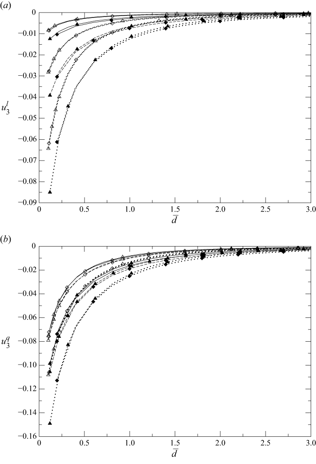
 \begin{align} \boldsymbol {F}_{\!a}^l&=6\pi \mu a(\ell +\lambda )k_l\big[f_1^l\boldsymbol {e}_1+f_3^l\boldsymbol {e}_3\big],\, \boldsymbol {U}^l=k_l(\ell +\lambda )\big[u_1^l\boldsymbol {e}_1+u_3^l\boldsymbol {e}_3\big], \\[-12pt] \nonumber \end{align}
 \begin{align} \boldsymbol {F}_{\!a}^q&=6\pi \mu a \ell ^2 k_q\left[f_1^q\boldsymbol {e}_1+f_3^q\boldsymbol {e}_3\right]\!,\, \boldsymbol {U}^q=k_q\big(\ell ^2+a^2/3\big)\left[u_1^q\boldsymbol {e}_1+u_3^q\boldsymbol {e}_3\right]\!, \\[-12pt] \nonumber \end{align}
 \begin{align} {\boldsymbol\varGamma }_a^l&=4\pi \mu a^3 k_l c_2^l\boldsymbol {e}_2,\, {\boldsymbol \varOmega }^l=k_l\big(w_2^l/2\big)\boldsymbol {e}_2,\, {\boldsymbol\varGamma }_a^q=8\pi \mu a^3\ell k_l c_2^q\boldsymbol {e}_2,\, {\boldsymbol \varOmega }^q=k_q\ell w_2^q\boldsymbol {e}_2. \\[9pt] \nonumber \end{align}


Each of the above vectors is scaled using the values provided for the sphere immersed in an unbounded fluid by the usual Faxen (Reference Faxen1922, Reference Faxen1923) relations. The ellipsoid behaviour in the addressed shear flows is here characterised by 12 normalised quantities
 $f_1^l,\ldots ,w_2^q.$
For the triplet
 $\alpha =(\alpha _0,\alpha _1,\alpha _2)$
let us introduce the Stokes velocity
 $\boldsymbol {u}^{\alpha }_a=[\alpha _0+\alpha _1 x^{\prime}_3+\alpha _2 (x^{\prime}_3)^2]\boldsymbol {e}_1$
with
 $x^{\prime}_3=\boldsymbol {x}'\boldsymbol{\cdot }\boldsymbol {e}_3.$
In the absence of a wall (2.14) and (4.3) give the component along
 ${\tilde {\boldsymbol {e}}}_i$
of the force
 $\boldsymbol {F}_{\!a}^{nw}$
and of the torque
 ${\varGamma }_a^{nw}$
exerted on the ellipsoid held fixed in the ambient velocity
 $\boldsymbol {u}^{\alpha }_a.$
One gets
 \begin{equation} \boldsymbol {F}_{\!a}^{nw}=16\pi \mu a(\alpha _0 I+\alpha _2 J)\biggl [{{\cos \beta {\tilde {\boldsymbol {e}}}_1}\over {\chi +\alpha _1}} +{{\sin \beta {\tilde {\boldsymbol {e}}}_3}\over {\chi +s^2\alpha _3}}\biggr ],\, {\varGamma }_a^{nw}={{16\pi \mu \alpha _1 a J\boldsymbol {e}_2}\over {\chi -\alpha _2/s^2}} \end{equation}
with, for the ellipsoid selected semi-axis
 ${\tilde a}_i,$
the following definitions and identities:
 \begin{equation} I=\int _S {{v{\rm d}S}\over {4\pi a}}=1,\, J=\int _S{{\big[\left(\cos \beta {\tilde x}_3\right)^2+\left(\sin \beta {\tilde x}_1\right)^2\big]v{\rm d}S}\over {4\pi a}}= {{a^2\big(s^2\cos ^2\beta +\sin ^2\beta \big)}\over {3}}. \end{equation}
The force
 $\boldsymbol {F}_{\!h}^{nw}$
and torque
 ${\boldsymbol\varGamma }_h^{nw}$
applied on the ellipsoid when it translates at velocity
 $\boldsymbol {U}={\tilde U}_1{\tilde {\boldsymbol {e}}}_1+{\tilde U}_3{\tilde {\boldsymbol {e}}}_3$
and rotates at velocity
 ${\boldsymbol \varOmega }=\varOmega _2{\tilde {\boldsymbol {e}}}_2$
in a quiescent and unbounded fluid can be obtained from Oberbeck (Reference Oberbeck1876), Edwardes (Reference Edwardes1892) and Lamb (Reference Lamb1932) and read
 \begin{equation} \boldsymbol {F}_{\!h}^{nw}=-16\pi \mu a\biggl [{{{\tilde U}_1{\tilde {\boldsymbol {e}}}_1}\over {\chi +\alpha _1}} +{{{\tilde U}_3{\tilde {\boldsymbol {e}}}_3}\over {\chi +s^2\alpha _3}}\biggr ],\, {\boldsymbol\varGamma }_h^{nw}=-{{16\pi \mu a^3(1+s^2)\varOmega _2\boldsymbol {e}_2}\over {3[\chi -\alpha _2/s^2]}}. \end{equation}
Expressing
 $({\tilde {\boldsymbol {e}}}_1,{\tilde {\boldsymbol {e}}}_3)$
in terms of
 $\beta$
and
 $(\boldsymbol {e}_1,\boldsymbol {e}_3),$
using (4.10)–(4.12) and then letting
 $a/\ell$
vanish provides the quantities
 $f_1^{l,0},\ldots ,w_2^{q,0}$
associated with those occurring in (4.7)–(4.9) by adequately selecting
 $\alpha .$
Since not used in this work, the values for the ellipsoid at rest are not reported here. For the freely suspended ellipsoid one arrives at
 \begin{equation} u_1^{l,0}=u_1^{q,0}=1,\, u_1^{3,0}=u_1^{3,0}=0,\, w_2^{l,0}=w_2^{q,0}={{2 \big(s^2\cos ^2\beta +\sin ^2\beta \big)}\over {1+s^2}}. \end{equation}
As expected, for the sphere
 $(s=1)$
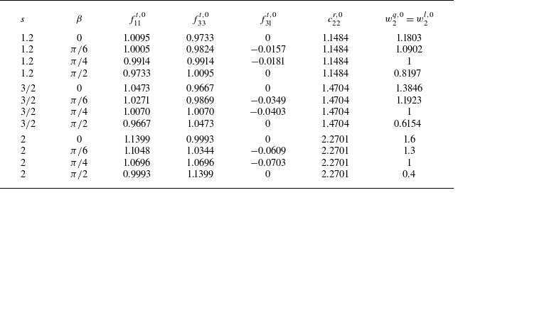
each free-space quantity given in (4.5)–(4.6) and (4.13) is either zero or unity. The values of those quantities, calculated with the Maple software, are provided in table 1 for
 $s=1.2,1.5,2$
and some orientations
 $\beta $
.
4.2. Numerical implementation and comparisons for a spheroid
In this work the key boundary-integral equation (3.4) is numerically solved by a boundary-element method (BEM). For details regarding this efficient approach the reader is directed to Brebbia, Telles & Wrobel (Reference Brebbia, Telles and Wrobel1984), Pozrikidis (Reference Pozrikidis1992) and Bonnet (Reference Bonnet1995). In contrast to most usual implementations, six-node curved (P2) triangular boundary elements are used to mesh the particle surface. This is done by spreading on this boundary
 $N$
nodal points at which each Cartesian component of the stress
 $\boldsymbol {f\!}_a+\boldsymbol {f}$
is unknown. The resulting discretised form of (3.4), obtained as explained in detail in Sellier (Reference Sellier2010), is enforced at each node and this yields a
 $3N$
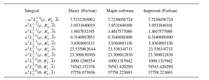
-equation linear system. Since it has a fully populated and non-symmetric matrix, this linear system is solved with Gaussian elimination. As shown in § 3.2, the Green tensor involves seven Hankel integrals (recall (3.6)–(3.9)) which are accurately computed, with a prescribed accuracy
 $\epsilon _a,$
by using an iterative Gaussian quadrature briefly explained and tested in Appendix A (see table 6). For the present work, all the computations have been performed with
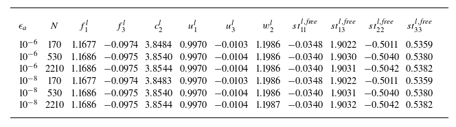
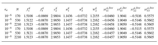
 $\epsilon _a={10^{-6}}$
which is a sufficient accuracy level to provide the normalised friction coefficients and velocity components with a four-digit accuracy (see tables 7 and 8 in Appendix A). When the normalised particle–wall gap
 ${\overline {d}}=d/a$
becomes small and/or the normalised wall slip length
 $\overline {\lambda }=\lambda /a$
becomes large a refined mesh is needed. Actually, attention is restricted to the range
 $\overline {\lambda } \leqslant 5$
because our numerical experiments reveal that the results are nearly unchanged beyond
 $\overline {\lambda }=5$
. For example, our computations in bipolar coordinates for a sphere translating normal to a plane slip wall (as for table 9 in Appendix C) show that the error
 $|f^t_{33}(\overline {\lambda }=5)/(f^t_{33}(\overline {\lambda }=\infty )-1|$
is at the most 4 % for
 $d/a\geqslant 1.0453$
. (The value
 $f^t_{33}(\overline {\lambda }=\infty )$
is for a plane free surface and has been given in closed form by Brenner (Reference Brenner1961).) This is because, as
 $\overline {\lambda } \rightarrow \infty$
, the Navier slip condition quickly reduces to the zero-shear condition prevailing on a plane and undisturbed free surface. As later illustrated (see, for instance, tables 7 and 8 in Appendix A), a quite sufficient four-digit accuracy has been obtained for
 ${\overline {d}}\geqslant O(0.05)$
and
 $\overline {\lambda }\leqslant O(5)$
using a quite reasonable value of
 $N.$
More precisely, for the reported results, taking
 $N\leqslant 3000$
was sufficient and this was made possible by using six-node curved boundary elements.
As mentioned in the introduction, accurate numerical results for a sphere with radius
 $a$
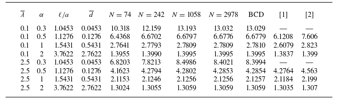
have been obtained using the bipolar coordinates in O’Neill & Bhatt (Reference O’Neill and Bhatt1991), Loussaief et al. (Reference Loussaief, Pasol and Feuillebois2015) and Ghalia et al. (Reference Ghalia, Feuillebois and Sellier2016). Those results permit one to test the accuracy of the present boundary-integral method implementation. A good agreement has been found between the two quite different approaches. Some illustrative results are provided in Appendix C (see tables 9–11). For example, a three-digit accuracy is obtained for the friction coefficient
 $f_{33}^t$
of a sphere with radius
 $a$
translating normal to the wall for
 ${\overline {d}}\sim 0.0453$
and
 $\overline {\lambda }=2.5$
putting
 $N=2978$
nodes on the sphere boundary. Finally, the present implementation predictions have been also well compared for a spheroidal body settling near a no-slip wall (Hsu & Ganatos Reference Hsu and Ganatos1994). In that case the Green tensor is the Blake (Reference Blake1971) tensor and the comparisons reported in Sellier (Reference Sellier2005) (see table 1 here) are retrieved.
4.3. Results for a large ellipsoid–wall gap compared with the wall slip length
The normalised quantities introduced in § 4.1 depend on
 $(s,{\overline {d}},\overline {\lambda },\beta ).$
According to (3.12), for
 $\epsilon =\lambda /d\ll 1$
each friction coefficient obeys the ‘recipe’ established in § 3.3: it is unchanged, at
 $O \big(\epsilon ^2 \big),$
when replacing
 $({\overline {d}},\overline {\lambda })$
with
 $({\overline {d}}+\overline {\lambda },0).$
When recast in terms of the normalised velocities, (3.13) shows that
 $(u_1^l, u_3^l)$
and
 $\omega _2^l$
also obey the ‘recipe’ for the ambient ‘linear’ shear flow. For the ambient quadratic shear flow the ‘recipe’ is not valid. Indeed, (3.14) yields
 $\text{for }{ k=1,3}$
 \begin{align} u_k^q({\overline {d}},\overline {\lambda })&=u_k^q({\overline {d}}+\overline {\lambda },0)+{{6\overline {\lambda } \big[u_k^q\left({\overline {d}}+\overline {\lambda },0\right)-u_k^l\left({\overline {d}}+\overline {\lambda },0\right)\big]}\over {3\ell /a+a/\ell }}+O \big(\epsilon ^2 \big); \end{align}
 \begin{align} \omega _2^q({\overline {d}},\overline {\lambda })&=\omega _2^q({\overline {d}}+\overline {\lambda },0)+\overline {\lambda }\left({{a}\over {\ell }}\right)\big[ \omega _2^q({\overline {d}}+\overline {\lambda },0)-\omega _2^l\left({\overline {d}}+\overline {\lambda },0\right)\big]+O (\epsilon ^2). \end{align}
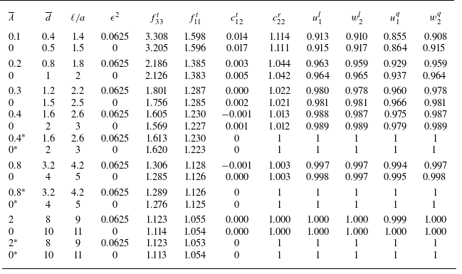
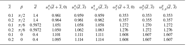
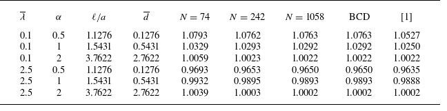
The ‘recipe’ is first numerically tested for a spherical particle and some normalised quantities. Some results are displayed in table 2 for
 $\lambda /d=0.25$
and
 ${\overline {d}} \geqslant 0.4$
(i.e.
 $l/a\geqslant 1.4).$
Some computed normalised quantities for a sphere with radius
 $a$
and different pairs
 $(\overline {\lambda },{\overline {d}}).$
Results are given for the wall slip length
 $\lambda \gt 0$
with wall–sphere gap
 $d\gg \lambda$
and for the no-slip wall with wall–sphere gap
 $d+\lambda .$
Here,
 $\epsilon =\lambda /d=0.25.$
For
 $l/a\geqslant 2.6$
the asymptotic predictions (4.16) are given in the rows for which the value of
 $\overline {\lambda }$
has an asterisk.

The reported three-digit values are obtained by the accurate bipolar method. Clearly, the results agree very well for the friction coefficients and
 $(u_1^l,\omega _2^l)$
with the proposed ‘recipe’ for
 $\ell /a$
in the considered range
 $[1.4,11].$
Actually, for
 $\ell /a$
large and
 $\overline {\lambda }\leqslant O(1)$
each quantity receives an expansion versus small
 $a/\ell$
either built from Khabthani et al. (Reference Khabthani, Sellier and Feuillebois2013) or available in Ghalia et al. (Reference Ghalia, Feuillebois and Sellier2016). The estimates derived there for the friction coefficients
 $f_{11}$
and
 $f_{33}$
read
 \begin{equation} f_{kk}=1+f_k\left({{a}\over {\ell }}\right)+f_k[f_k-\overline {\lambda }]\left({{a}\over {\ell }}\right)^2+O\left(\left({{a}\over {\ell }}\right)^3\right),\, f_1={{9}\over {16}},\, f_3={{9}\over {8}}. \end{equation}
Moreover,
 $c_{12}^t\sim 0$
while the other non-zero quantities are approximated by unity. Note that each approximation (4.16) obeys the ‘recipe’ obtained in § 3.3. The resulting estimates are, for comparison, also provided in table 2 for
 $\ell /a\geqslant 2.6.$
The results are in full agreement with the predicted ‘recipe’ for the concerned normalised quantities. Remarkably, the velocity
 $\omega _2^q$
seems to also obey the ‘recipe’ despite (4.15). This is because
 $\omega _2^q\sim \omega _2^l$
for the sphere (see also the asymptotics provided in Ghalia et al. (Reference Ghalia, Feuillebois and Sellier2016) for
 $\ell /a$
large). Application of (4.14) supplies values of
 $u_1^q({\overline {d}},\overline {\lambda })$
close to the reported ones obtained using the bipolar coordinates method. For instance, (4.14) gives
 $u_1^q(0.4,0.1)=0.8574, u_1^q(0.8,0.2)=0.9311$
and
 $u_1^q(1.2,0.3)=0.9620.$
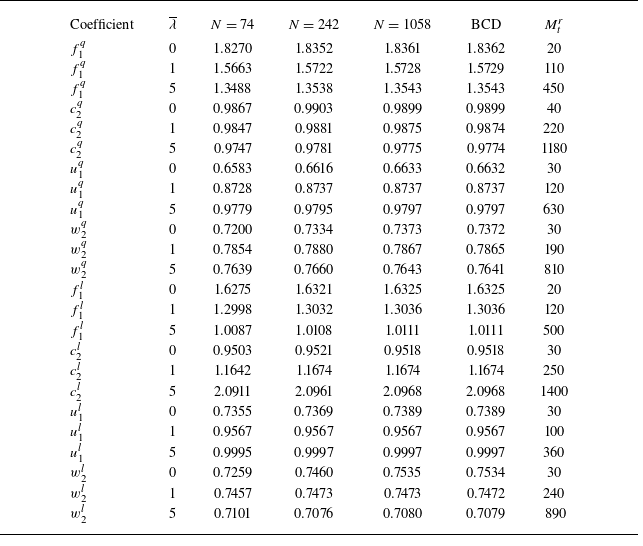
Comparisons have been also made for the considered ellipsoids using the BEM code. For that purpose, a refined mesh on the ellipsoid surface is used so that results with a four-digit accuracy are obtained (see tables 7 and 8).
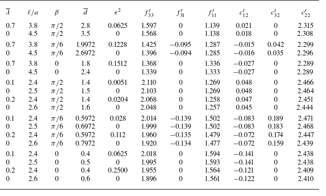
The computed friction coefficients defined by (4.1)–(4.2) are given for the
 $s=2$
ellipsoid in table 3 for
 $\lambda /d\leqslant 0.5,$
different orientations
 $\beta$
and
 ${\overline {d}} \geqslant 0.4.$
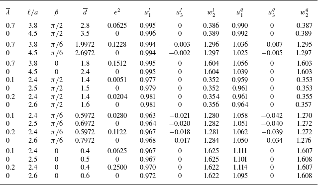
Clearly, each coefficient is seen to nicely obey the proposed ‘recipe’. For the same ellipsoid and settings the normalised velocities defined by (4.7)–(4.9) are provided in table 4.
Computed friction coefficients for the
 $s=2$
ellipsoid taking a few orientation angles
 $\beta$
and pairs
 $(\overline {\lambda },\ell /a).$
The normalised wall–ellipsoid gap
 ${\overline {d}}=\ell /a-(\sin ^2\beta +s^2\cos ^2\beta )^{1/2}$
(see § 4.1) is indicated and
 $N=2210$
nodes are put on the ellipsoid boundary. For given
 $\beta$
the results are reported for a wall slip length
 $\lambda \gt 0$
with wall–ellipsoid gap
 $d\gt \lambda$
and for the no-slip wall with wall–ellipsoid gap
 $d+\lambda .$
Here,
 $\epsilon =\lambda /d$
.

Counterpart of table 3 giving the normalised velocity components for the
 $s=2$
ellipsoid freely suspended in a ‘linear’ or quadratic ambient shear flow.

As predicted, the normalised velocities
 $u_1^l, u_3^l$
and
 $\omega _2^l$
satisfy the proposed ‘recipe’. The differences
 $u_1^q({\overline {d}},\overline {\lambda })-u_1^q({\overline {d}}+\overline {\lambda },0)$
are of order
 $0.01$
and the prediction,
 $u_{1,p}^q({\overline {d}},\overline {\lambda }),$
from (4.14) is compared, in table 5, with the computed values
 $u_1^q({\overline {d}},\overline {\lambda })$
and
 $u_1^q({\overline {d}}+\overline {\lambda },0).$


It turns out that (4.14) nicely approaches
 $u_1^q({\overline {d}},\overline {\lambda }).$
Comparisons for the normalised angular velocity predicted by (4.15),
 $\omega _{2,p}^q({\overline {d}},\overline {\lambda }),$
are also provided in table 5. For
 $\beta =0$
the predictions are excellent. For
 $\beta =\pi /6,\pi /2$
the values obtained from (4.15) are pretty good and always below
 $\omega _{2}^q({\overline {d}}+\overline {\lambda },0)$
as is
 $\omega _{2}^q({\overline {d}},\overline {\lambda }).$
For these orientations, the small difference
 $\omega _{2}^q({\overline {d}},\overline {\lambda })-\omega _{2,p}^q({\overline {d}},\overline {\lambda })$
is due to the neglected higher terms in small
 $\epsilon =\lambda /d.$
4.4. Rigid-body motion of a solid ellipsoid in a quiescent liquid
This subsection considers the rigid-body motion of an ellipsoid in a quiescent liquid. Note that a few results have been given in Feuillebois et al. (Reference Feuillebois, Ghalya and Sellier2012) for the coefficients
 $f_{11}^t, f_{33}^t, c_{22}^r$
and
 $c_{12}^t$
only for the
 $s=1.2$
nearly spherical ellipsoid with orientation
 $\beta =0$
(see figure 3
b). Those results for
 $f_{11}^t$
and
 $f_{33}^t$
are nearly those for the sphere and this is because the
 $s=1.2$
normalised surface area is
 $A_{1.2}\sim 1.02$
(recall that all ellipsoids have the sphere volume). A moderate shape sensitivity has been observed (when compared with the sphere) for the coefficients
 $c_{22}^r$
whatever
 $l/a$
and for
 $c_{12}^t$
only near the slip plane. For other orientations and larger values of
 $s\gt 1$
the coefficients
 $f_{31}^t$
and
 $c_{32}^t$
do not necessarily vanish and other trends (shape and orientation effects) are expected for the friction coefficients. This section investigates this key issue, restricting, for conciseness, attention to some
 $s\gt 1$
ellipsoids.
For given
 $(s,{\overline {d}}),$
a normalised quantity
 $\textit {Q}$
(such as the friction coefficients in (4.1)–(4.2), the normalised velocities in (4.7)–(4.9), etc.) can depend on both the particle orientation
 $\beta$
and the normalised wall slip length
 $\overline {\lambda }$
in a non-trivial way. This is also the case for the local surface stress
 $\boldsymbol {f}$
exerted on the particle boundary
 $S.$
As before, the
 ${(}0{)}$
superscript is used to designate the value obtained when neglecting the wall–particle interactions. Here,
 $\delta \boldsymbol {f}=\boldsymbol {f}-\boldsymbol {f}^{{(}0{)}},$
which is due to the interactions with the wall, has a typical magnitude
 $\delta \!f$
on the part
 $S_w$
of
 $S$
where it is not small. Then, the magnitude of
 $\textit {Q}-\textit {Q}^{(0)}$
is dictated by the product
 ${\overline S}_w\delta \!f$
, where
 ${\overline S}_w$
is the area of
 $S_w.$
For small enough wall–particle gap and slip on the wall, the surface
 $S_w$
is the part of
 $S$
located close to the wall. In such circumstances
 ${\overline S}_w$
increases with
 $\beta$
(recall figure 3) and
 $\delta \!f$
increases with
 $\overline {\lambda }$
so that one can predict the sensitivity of
 $\textit {Q}-\textit {Q}^{(0)}$
to
 $(\overline {\lambda },\beta ).$
When
 $\overline {\lambda }$
is larger the flow on the wall might be even speeded up when compared with the free-space case so that the points of
 $S_w$
are no longer close to the wall and the behaviour of
 $\textit {Q}-\textit {Q}^{(0)}$
can become non-trivial.
A numerical analysis has been performed for
 $s=1.5,2$
and similar new behaviours have been observed. However,
 $A_{3/2}\sim 1.09$
while
 $A_{2}\sim 1.26$
so that the shape effects have been found to be more pronounced for
 $s=2$
than for
 $s=1.5.$
This is already the case in the absence of a wall, as observed for the free-space coefficients given in table 1 for
 $s=1.2,1.5,2.$
Indeed, for each coefficient the difference from its value for the sphere
 $(s=1)$
increases in magnitude as
 $s$
increases. For conciseness, the results reported in this subsection are for the
 $s=2$
ellipsoid and, for comparison, for the sphere. The computations for the ellipsoid are achieved using the present BEM approach and stopped at the small value
 ${\overline {d}}\sim 0.2$
because of numerical limitations, while the bipolar coordinates method (Ghalia et al. Reference Ghalia, Feuillebois and Sellier2016) is used for the sphere and permits one to consider smaller sphere–wall gaps. (Accordingly, in figures 4, 6, 9 and 10 the curves for the sphere are obtained with the bipolar coordinates method and extend to small values of
 $d.$
)
Drag coefficients
 $f^t_{33}$
(a) and
 $f^t_{11}$
(b) versus the normalised particle–wall gap
 ${\overline {d}},$
for the
 $s=2$
ellipsoid translating normal or tangent to a plane slip wall and having orientation
 $\beta =0$
(square),
 $\beta =\pi /4$
(triangle) and
 $\beta =\pi /2$
(circle). The wall has normalised slip length
 ${\overline \lambda }=0$
(dotted curves),
 ${\overline \lambda }=0.7$
(dashed curves) and
 ${\overline \lambda }=5$
(solid curves). For comparison, the results for the sphere (no symbol) are also plotted.

Below the results for all coefficients
 $f^t_{33}, f^t_{11}, c^r_{22}, c^t_{12}, f^t_{31}$
and
 $c^t_{32}$
are given versus the normalised particle–wall gap
 $\overline {d}$
for different orientations
 $\beta$
and normalised wall slip lengths
 $\overline {\lambda }.$
Each coefficient depends on
 $(s,{\overline {d}},\overline {\lambda },\beta ).$
Some coefficients are found to monotonically evolve with increasing
 $\beta$
in the same fashion whatever
 ${\overline {d}}.$
Some other coefficients’ sensitivity to
 $\beta$
depends on
 ${\overline {d}}.$
For those coefficients additional plots show for
 ${\overline {d}}=0.2$
the variation of the coefficient versus
 $\beta$
for different wall slips.
First, the drag coefficients
 $f_{33}^t$
and
 $f_{11}^t$
are plotted in figure 4 for the
 $s=2$
ellipsoid, with orientations
 $\beta =0,\pi /4,\pi /2,$
and a volume equivalent sphere interacting with a plane with normalised slip
 $\overline {\lambda }=0,0.7,5.$
The coefficient
 $f_{33}^t,$
which is a drag coefficient, is positive. The results for
 $\overline {\lambda }=0.7$
are similar and thus omitted for clarity. As expected,
 $f_{33}^t$
increases monotonically for decreasing
 $\overline {d}$
or
 $\overline {\lambda }.$
In all cases,
 $f_{33}^t$
strongly depends on the particle location since it slowly tends to its free-space value
 $f_{33}^{t,0}$
(given in table 1) for large
 $\overline {d}$
and diverges at contact, as proven by the lubrication analysis for a sphere in Vinogradova (Reference Vinogradova1995) and for an ellipsoid with
 $\beta =0,\pi /2$
in Vinogradova (Reference Vinogradova1996, Reference Vinogradova1999). Moreover,
 $f_{33}^t$
is shape-sensitive (compare with the sphere) and shape effects actually depend on the ellipsoid orientation
 $\beta$
and location
 ${\overline {d}}$
. For
 $\beta =\pi /2$
the coefficient
 $f_{33}^t$
is larger than for the sphere but for
 $\beta =\pi /4$
it is larger or smaller than for the sphere for
 $\overline {d}$
large or small, respectively. As far from the wall,
 $f_{33}^t$
increases with increasing ellipsoid orientation
 $\beta$
whatever
 ${\overline {d}}.$
This is because the part of the ellipsoid surface where the friction plays a significant role increases with
 $\beta$
(see figure 3).
The second drag coefficient
 $f_{11}^t,$
also plotted in figure 4, is positive and smaller than
 $f_{33}^t$
as is well known for a sphere near a no-slip wall (O’Neill & Stewartson Reference O’Neill and Stewartson1967; Chaoui & Feuillebois Reference Chaoui and Feuillebois2003). It slowly asymptotes to its free-space value
 $f_{11}^{t,0}$
(see table 1) as
 $\overline {d}$
increases. Moreover, starting from
 $f_{11}^{t,0}$
for the distant wall case it monotonically increases or decreases as
 $\overline {d}$
drops when the wall slip length is sufficiently small or large (here
 $\overline {\lambda }=5),$
respectively. For a slip wall
 $(\overline {\lambda }\gt 0)$
one expects that
 $f_{11}^t$
has a finite limit at contact, like for the sphere. For instance, it is found in Ghalia et al. (Reference Ghalia, Feuillebois and Sellier2016) that
 $f_{11}^t\sim 0.98$
at contact for
 $\overline {\lambda }=5.$
Shape effects are dictated by the orientation
 $\beta$
(i.e. are weakly dependent on
 ${\overline {d}}).$
For
 $\beta =\pi /2$
the coefficient
 $f_{11}^t$
is slightly (small shape effects) lower than for the sphere whatever the wall slip. In contrast, for
 $\beta =0$
shape effects occur and
 $f_{11}^t$
is larger than for the sphere whatever
 $\overline {d}$
for
 $\overline {\lambda }=0.7,5$
and either larger or smaller for
 $\overline {\lambda }=0,$
depending on
 ${\overline {d}}.$
Not surprisingly, for given
 $(s,{\overline {d}},\beta )$
the quantity
 $f_{11}^t$
drops when increasing
 $\overline {\lambda }.$
Finally, the variation of
 $f_{11}^t$
with the ellipsoid orientation
 $\beta$
depends in a non-trivial way on
 $({\overline {d}},\overline {\lambda }).$
Indeed, for
 $\overline {d}$
sufficiently large
 $f_{11}^t$
decreases when increasing
 $\beta$
whatever the wall slip as is the case in the absence of a wall, but for small enough
 $\overline {d}$
this behaviour is no longer true.
Coefficients
 $f^t_{11}$
and
 $c^r_{22}$
for the
 $s=2$
ellipsoid, with orientation
 $\beta ,$
interacting with a plane slip wall with normalised slip length
 ${\overline \lambda }=0$
(dotted curves),
 ${\overline \lambda }=0.7$
(dashed curves) and
 ${\overline \lambda }=5$
(solid curves). (a) Coefficients
 $f^t_{11}$
(no symbol) and
 $c^r_{22}$
(star) versus
 $\beta /\pi$
for
 ${\overline {d}}=0.2.$
(b) Coefficient
 $c^r_{22}$
versus
 ${\overline {d}}$
for the sphere (no symbol) and the
 $s=2$
ellipsoid with
 $\beta =0$
(square),
 $\beta =\pi /4$
(triangle) and
 $\beta =\pi /2$
(circle).

This behaviour of
 $f_{11}^t$
is illustrated for
 ${\overline {d}}=0.2$
in figure 5 which plots
 $f_{11}^t$
versus
 $\beta /\pi$
for
 $\overline {\lambda }=0,0.7,5.$
For a sufficiently large wall slip
 $f_{11}^t$
decreases when increasing
 $\beta$
while for a small slip (here for
 $\overline {\lambda }=0)$
the coefficient
 $f_{11}^t$
first slightly decreases and then increases for increasing
 $\beta .$
This is due to the strong particle–wall interactions, prevailing for a small slip, which apply to a larger part of the ellipsoid surface close to the wall when
 $\beta$
approaches
 $\pi /2$
(recall figure 3).
The torque friction coefficient
 $c_{22}^r$
is also plotted in figure 5 still for
 $\beta =0,\pi /4,\pi /2$
and
 $\overline {\lambda }=0,0.7,5.$
It is positive and strongly shape-dependent since for the ellipsoid being about twice that for the sphere, as is the case for the free-space value
 $c_{22}^{r,0}$
(see table 1). For the sphere,
 $c_{22}^r$
increases for decaying sphere–wall gap whatever
 $\overline {\lambda }$
and reaches at contact a finite value only for
 $\overline {\lambda }\gt 0$
(see O’Neill & Stewartson (Reference O’Neill and Stewartson1967) for the no-slip wall and Loussaief et al. (Reference Loussaief, Pasol and Feuillebois2015) for the slip wall). For the ellipsoid,
 $c_{22}^r$
varies in a similar way except for a sufficiently large wall slip (here
 $\overline {\lambda }=5)$
and
 $\beta =\pi /2.$
In that case,
 $c_{22}^r$
decreases monotonically as the ellipsoid approaches the wall. Note that
 $c_{22}^r-c_{22}^{r,0}$
vanishes for large
 $\overline {d}$
faster for the sphere (for which, see Ghalia et al. (Reference Ghalia, Feuillebois and Sellier2016), it is
 $O(1/{\overline {d}}^{3})$
) than for the ellipsoid. As deemed, for both particles
 $c_{22}^r$
decreases when increasing the wall slip. For
 $\overline {d}$
small enough and
 $\overline {\lambda }$
sufficiently small
 $c_{22}^r$
first increases with
 $\beta ,$
further decreases with
 $\beta$
and takes its largest value for
 $\beta$
close to
 $\pi /2.$
This property is illustrated in figure 5 for
 ${\overline {d}}=0.2.$
For other settings
 $({\overline {d}},\overline {\lambda })$
the coefficient
 $c_{22}^r$
drops for increasing
 $\beta$
as is the case in the absence of a wall.
Friction coefficient
 $c^t_{12}$
for the
 $s=2$
ellipsoid, with orientation
 $\beta ,$
interacting with a plane slip wall with normalised slip length
 ${\overline \lambda }=0$
(dotted curves),
 ${\overline \lambda }=0.7$
(dashed curves) and
 ${\overline \lambda }=5$
(solid curves). (a) Coefficient
 $c^t_{12}$
versus
 ${\overline {d}}$
for the sphere (no symbol) and for the
 $s=2$
ellipsoid with
 $\beta =0$
(square),
 $\beta =\pi /4$
(triangle) and
 $\beta =\pi /2$
. (b) Coefficient
 $c^t_{12}$
versus
 $\beta /\pi $
for the
 $s=2$
ellipsoid and
 ${\overline {d}}=0.2.$
For comparison, the values for the sphere are indicated as horizontal lines with open circles.

The coupling coefficient
 $c_{12}^t$
is plotted, still versus
 $\overline {d}$
and for
 $\overline {\lambda }=0,0.7,5,$
in figure 6 for three orientations
 $\beta$
and also versus
 $\beta /\pi$
for
 ${\overline {d}}=0.2.$
It is either positive or negative, of rather small magnitude and vanishes slowly as
 $\overline {d}$
becomes large. As
 $\overline {d}$
decreases,
 $|c_{12}^t|$
monotonically increases for the sphere while this is not always the case for the ellipsoid. For example, for a sufficiently small ellipsoid–wall gap it appears that
 $|c_{12}^t|$
decreases with
 $d/a$
for
 $\overline {\lambda }=0.7$
and
 $\beta =\pi /4.$
At contact the value is finite for each particle. The sensitivity of
 $c_{12}^t$
to the particle shape is strong: the signs of
 $c_{12}^t$
for the sphere and for the ellipsoid are different for
 $\overline {\lambda }=0,5$
while for
 $\overline {\lambda }=0.7$
and depending on
 $\overline {d}$
identical signs can be obtained. The variation of
 $|c_{12}^t|$
with the wall slip is not trivial and strongly depends on the ellipsoid orientation. For instance, if
 $\beta =0$
then
 $|c_{12}^t|$
significantly decreases when increasing the slip. In contrast, for
 $\beta =\pi /2$
then
 $|c_{12}^t|$
slightly varies and can either increase or decrease with
 $\overline {\lambda }$
sufficiently small or large, respectively. Moreover, as illustrated in figure 6 for
 ${\overline {d}}=0.2,$
the quantities
 $c_{12}^t$
and
 $|c_{12}^t|$
vary with
 $\beta$
and
 $\overline {\lambda }$
in a non-trivial fashion. Clearly,
 $c_{12}^t$
increases with the orientation
 $\beta$
whatever the wall slip. For a sufficient slip,
 $c_{12}^t$
is larger than for the sphere whatever the orientation (here
 $\overline {\lambda }=5).$
For other slip it is smaller or larger than for the sphere depending on
 $\beta .$
Let
 $\beta _c$
be the critical orientation at which
 $c_{12}^t=0$
for
 $\overline {\lambda }=0.$
Here,
 $\beta _c/\pi \sim 0.39$
and for
 $\beta \gt \beta _c$
then
 $c_{12}^t$
is positive and increases with
 $\overline {\lambda }$
which is a somewhat unexpected behaviour because one usually expects a positive friction coefficient to decrease when increasing the slip on the wall. In contrast, for
 $\beta \lt \beta _c$
there exists a critical normalised slip
 $\overline {\lambda }_{cr}(\beta )$
for which
 $c_{12}^t=0$
and then
 $c_{12}^t$
becomes negative or positive for
 $\overline {\lambda }\lt \overline {\lambda }_{cr}(\beta )$
or
 $\overline {\lambda }\gt \overline {\lambda }_{cr}(\beta ),$
respectively. Note that the magnitude of
 $c_{12}^t$
decreases from its value for the no-slip wall to zero as
 $\overline {\lambda }$
increases from zero to
 $\overline {\lambda }_{cr}(\beta )$
and then increases as
 $\overline {\lambda }$
further increases. In summary, there is a non-trivial sensitivity of
 $|c_{12}^t|$
to increase of slip on the wall for a given ellipsoid orientation
 $\beta \lt \beta _c.$
Coefficients
 $f^t_{31}$
and
 $c^t_{32}$
for the
 $s=2$
ellipsoid, with orientation
 $\beta ,$
interacting with a plane slip wall with normalised slip length
 ${\overline \lambda }=0$
(dotted curves),
 ${\overline \lambda }=0.7$
(dashed curves) and
 ${\overline \lambda }=5$
(solid curves). (a) Coefficient
 $f^t_{31}$
versus
 ${\overline {d}}$
for
 $\beta =\pi /6$
(diamond) and
 $\beta =\pi /4$
(triangle). (b) Coefficients
 $f^t_{31}$
(no symbol) and
 $c^t_{32}$
(star) versus
 $\beta /\pi ,$
for
 ${\overline {d}}=0.2.$

The coefficient
 $f_{31}^t,$
displayed in figure 7, vanishes for
 $\beta =0,\pi /2$
and for a sphere. For other ellipsoid orientations it is strictly negative. Therefore, it is strongly shape-dependent. Here, it is plotted for
 $\beta =\pi /6, \pi /4$
and its magnitude, much smaller than that of the drag force coefficient
 $f_{33}^t,$
is comparable with that of
 $c_{12}^t.$
Moreover,
 $|f_{33}^t|$
vanishes slowly away from the wall and increases as the ellipsoid approaches the slip wall. At contact,
 $f_{31}^t$
seemingly reaches a finite value. Note that
 $|f_{31}^t|$
decreases as the slip increases which is a presumable behaviour. Finally, as shown in figure 7, for
 ${\overline {d}}=0.2,$
the coefficient
 $f_{31}^t$
first decreases and then further increases when the orientation
 $\beta$
increases. Therefore, its magnitude admits a largest value for some specific ellipsoid orientation close to
 $3\pi /10.$
Note that whatever the slip on the wall the plot of
 $f_{31}^t$
is, notably, nearly (but not exactly) symmetric with respect to the
 $\theta /\pi =0.25$
vertical line.
Coefficient
 $c^t_{32}$
versus
 $d/a$
for the
 $s=2$
ellipsoid translating with orientations
 $\beta =\pi /6$
(diamond) and
 $\beta =\pi /4$
(triangle) normal to a plane slip wall with normalised slip length
 ${\overline \lambda }=0$
(dotted curves),
 ${\overline \lambda }=0.7$
(dashed curves) and
 ${\overline \lambda }=5$
(solid curves).

Like
 $f_{31}^t,$
the coupling coefficient
 $c_{32}^t$
vanishes for a sphere and also, by symmetry, for the ellipsoid with orientation
 $\beta =0,\pi /2.$
It is plotted in figure 8 for
 $\beta =\pi /6, \pi /4.$
In contrast to
 $f_{31}^t,$
it is strictly positive and can be, for small
 $d/a,$
of significant magnitude. This indicates strong shape effects, near the wall, for this coefficient. Moreover,
 $c_{32}^t$
slowly vanishes far from the wall and monotonically increases as
 $\overline {d}$
decreases whatever the wall slip. As for
 $|f_{31}^t|,$
the coefficient
 $c_{32}^t$
decreases when increasing the slip. Whatever
 ${\overline {d}},$
the coefficient
 $c_{32}^t$
increases and then decreases as the orientation increases. This behaviour is also shown in figure 7 for
 ${\overline {d}}=0.2.$
4.5. Ellipsoidal particle immersed in a linear or quadratic ambient shear flow
This subsection provides and discusses some results obtained for an ellipsoid freely suspended in a ‘linear’ or quadratic ambient shear flow. For conciseness, the results for the ellipsoid held fixed are not reported. Here, the behaviours of the
 $s=1.5,2$
ellipsoids are considered and compared with the results obtained for the sphere in Ghalia et al. (Reference Ghalia, Feuillebois and Sellier2016). When freely suspended in the ambient ‘linear’ or quadratic shear flow tangent to the wall, each considered body adopts a translational velocity with normalised components
 $u_1^l$
(or
 $u_1^q)$
tangent to the wall and
 $u_3^l$
(or
 $u_3^q)$
normal to the wall. Those normalised velocities are introduced in (4.8)–(4.9) and computed with a three-digit accuracy for different settings
 $(s,{\overline {d}},\overline {\lambda },\beta ).$
For examples and further reference, some results for the
 $s=1.5$
ellipsoid are displayed in the supplementary material (see the table there) available at https://doi.org/10.1017/jfm.2025.10753.
Normalised velocity
 $u_1^q$
versus
 ${\overline {d}}$
for the freely suspended sphere (no symbols) and the
 $s=1.5$
(open symbols) and
 $s=2$
(filled symbols) ellipsoids. Each ellipsoid orientation is
 $\beta =0\,$
(a, squares),
 $\beta =\pi /4\,$
(b, triangles) and
 $\beta =\pi /2\,$
(c, circles). The normalised slip on the plane wall is
 ${\overline \lambda }=0$
(dotted curves),
 ${\overline \lambda }=0.7$
(dashed curves) and
 ${\overline \lambda }=5$
(solid curves).

The normalised velocity
 $u_1^q$
is plotted in figure 9 for
 $\beta =0,\pi /4,\pi /2$
and
 $\overline {\lambda }=0,0.7,5.$
Whatever the ellipsoid, it is positive and quickly tends to unity (recall (4.13)) as
 $\overline {d}$
increases. For a sphere,
 $u_1^q\lt 1,$
i.e. the sphere–wall interactions always slow down the sphere. For
 $s=1.5, 2$
the ellipsoid–wall interactions can speed up the particle ending up with
 $u_1^q$
slightly above unity. For
 $s=2$
this is true whatever the slip on the wall for
 $\beta =0$
with
 $u_1^q$
increasing as the ellipsoid approaches the wall. This behaviour is modified when increasing the orientation
 $\beta$
: for instance, for
 $\beta =\pi /4, \pi /2$
the velocity
 $u_1^q$
this time decreases with
 $\overline {d}$
for
 $\overline {\lambda }=0,0.7.$
The
 $s=1.5$
ellipsoid behaviour is dictated only by the wall slip: its velocity
 $u_1^q$
either increases or decreases with decreasing
 $\overline {d}$
depending on
 $\overline {\lambda }$
and not on
 $\beta .$
When it decreases near the wall note that the ellipsoid is slightly slowed down near the wall.
The counterpart of figure 9 for the velocity
 $u_1^q$
is given in Appendix D (see figure 12). Except for large
 $\overline {\lambda },$
this time
 $u_1^q$
always decreases when the particle approaches the wall. Close to a highly slipping wall,
 $u_1^l$
marginally exceeds unity whatever the shape parameter
 $s.$
The behaviour of both
 $u_1^q$
and
 $u_1^l$
close the wall is considered in figure 10 versus
 $\beta /\pi$
for the
 $s=2$
ellipsoid and the small normalised gap
 ${\overline {d}}=0.2.$
Both velocities clearly depend on the ellipsoid orientation. For small slip
 $u_1^l$
decreases as
 $\beta$
increases because the part of the ellipsoid surface subject close to the wall to a large friction increases. For a large slip (here
 $\overline {\lambda }=5)$
the velocity increases somewhat with the orientation
 $\beta$
. This is because the wall now exerts a small stress on the part of the ellipsoid surface located in its vicinity. In contrast,
 $u_1^q$
decreases with increasing
 $\beta$
whatever the wall slip and for a sufficiently large slip
 $u_1^q\gt 1$
whatever
 $\beta .$
For a small or moderate slip (here for
 $\overline {\lambda }=0,0.7)$
there exists a critical orientation
 $\beta _c$
at which
 $u_1^q=1.$
For this ellipsoid orientation there are no global wall–particle interactions and
 $u_1^q\gt 1$
or
 $u_1^q\lt 1$
for
 $\beta \lt \beta _c$
or
 $\beta \gt \beta _c,$
respectively. Note that for
 ${\overline {d}}=0.2$
and
 $\beta /\pi \leqslant 0.22$
the wall–ellipsoid interactions speed up the
 $s=2$
ellipsoid whatever the slip on the wall, i.e. also for a no-slip wall. This is because for
 $\beta$
small the part of the ellipsoid surface near point
 $A$
in figure 3 is subject to a larger ambient velocity. For a large enough slip on the wall (here for
 $\overline {\lambda }=5)$
the wall–particle interactions speed up the particle
 $(u_1^q\gt 1)$
whatever its orientation because there is less friction at the point of the ellipsoid surface located close to the wall.
Plots of the angular velocities
 $\omega _2^q$
and
 $\omega _2^l$
are available in the supplementary material. It is found that:
-
(i) As
 $\overline {d}$
increases both velocities are positive and quickly asymptote to
$\omega _2^{q,0}$
given by (4.13).
-
(ii) Both velocities are weakly sensitive to the wall slip whatever
${\overline {d}}.$
-
(iii) At a given
$\overline {d}$
each velocity strongly depends on the ellipsoid orientation
$\beta$
except for
$\beta$
close to
$\beta =\pi /4.$
For this latter value note that
$\partial \omega _2^{l,0}/\partial s=0.$


Plots of the velocities
 $u_3^l$
and
 $u_3^q$
are provided and discussed in Appendix D (see figure 13). In the absence of a wall both vanish and the wall–particle interactions are found to increase as
 $\overline {d}$
decreases and to induce negative velocities of weak magnitude compared with
 $u_1^l$
and
 $u_1^q.$
Normalised velocities
 $u_1^l $
(triangle) and
 $u_1^q $
(star) versus
 $\beta /\pi ,$
for the
 $s=2$
ellipsoid and
 ${\overline {d}}=0.2.$
The normalised slip on the plane wall is
 ${\overline \lambda }=0$
(dotted curves),
 ${\overline \lambda }=0.7$
(dashed curves) and
 ${\overline \lambda }=5$
(solid curves).

Normalised velocities
 $u_3^l $
(triangle) and
 $u_3^q $
(star) versus
 $\beta /\pi $
for the
 $s=2$
ellipsoid and
 ${\overline {d}}=0.2$
. The normalised slip on the plane wall is
 ${\overline \lambda }=0$
(dotted curves),
 ${\overline \lambda }=0.7$
(dashed curves) and
 ${\overline \lambda }=5$
(solid curves).

For given
 $(s,{\overline {d}})$
the sensitivity of
 $u_3^l$
to
 $(\overline {\lambda },\beta )$
is the same as that previously found for the coefficient
 $f^t_{31}$
and illustrated for
 $s=2$
in figure 7. In the same spirit, figure 11 displays
 $u_3^l$
and
 $u_3^q$
versus
 $\beta /\pi$
for
 ${\overline {d}}=0.2$
and
 $\overline {\lambda }=0,0.7,5.$
The comments made for
 $f^t_{31}$
still hold:
 $u_3^l$
first decreases and then increases when
 $\beta$
increases and
 $|u_3^l|$
decreases, for given
 $\beta ,$
as
 $\overline {\lambda }$
increases. Note that whatever the slip on the wall
 $|u_3^l|$
reaches its maximum for
 $\beta$
close to
 $\pi /4.$
Moreover,
 $u_3^q$
exhibits the same behaviours as
 $u_3^l.$
5. Conclusions
A boundary-integral method is employed to investigate the hydrodynamic interactions between a solid particle and a plane slip wall where a Navier slip condition, with slip length
 $\lambda ,$
holds. It appeals to the Green velocity tensor complying with the Navier slip on the wall and the implemented collocation method resorts to six-node curved boundary elements on the particle surface. This permits one to accurately calculate, spreading on this surface a quite reasonable number of nodal points, the hydrodynamic force
 $\boldsymbol {F}_{\!h}$
and torque
 ${\boldsymbol\varGamma }_h$
exerted on the body when it moves in a quiescent fluid (resistance problem) and the body translational velocity
 $\boldsymbol {U}$
and angular velocity
 $\boldsymbol \varOmega$
when it is freely suspended in a prescribed ambient Stokes velocity field
 $\boldsymbol {u}_a$
(subject to the Navier slip on the wall). The advocated boundary procedure is efficient since it solely requires one to mesh the particle surface.
The boundary formulation shows that for small
 $\epsilon =\lambda /d$
the force
 $\boldsymbol {F}_{\!h}$
and the torque
 ${\boldsymbol\varGamma }_h$
are, at
 $O (\epsilon ^2 ),$
the same as for a no-slip wall located at a distance
 $d+\lambda$
from the particle. This ‘recipe’ also holds for the rigid-body motion
 $(\boldsymbol {U},{\boldsymbol \varOmega })$
due to the ambient ‘linear’ shear flow. As shown for the ambient quadratic shear flow, it, however, fails in general for other ambient flows.
Shape and orientation effects are considered for a family of inclined non-spheroidal ellipsoids having the same volume as the sphere with radius
 $a$
and orientation described by one Euler angle
 $\beta$
about a direction tangent to the wall. For translation normal to and rotation parallel with this direction
 $\boldsymbol {F}_{\!h}$
and
 ${\boldsymbol\varGamma }_h,$
once normalised as for the sphere, solely depend on two drag coefficients
 $f_{11}^t$
and
 $f_{33}^t,$
two coupling coefficients
 $c_{12}^t$
and
 $c_{32}^t$
and two additional friction coefficients
 $c_{22}^r$
and
 $f_{31}^t.$
Each coefficient’s sensitivity to the normalised wall–ellipsoid gap
 ${\overline {d}}=d/a,$
the ellipsoid shape and orientation
 $\beta$
and the normalised wall slip length
 $\overline {\lambda }=\lambda /a$
is then numerically investigated and some non-trivial behaviours have been found. Any coefficient more or less depends on the body shape in a simple manner while its sensitivity to
 $({\overline {d}},\overline {\lambda },\beta )$
can be complex. For instance, when
 $\overline {\lambda }$
becomes large enough the magnitude of
 $f_{11}^t, c_{12}^t$
and
 $c_{22}^r$
can decrease with
 $\overline {d}$
for some orientations
 $\beta$
and values of
 ${\overline {d}}.$
Moreover, some coefficients monotonically evolve with increasing
 $\beta$
while other coefficients first increase and then decrease in magnitude. Finally, while all other coefficients decrease in magnitude when increasing the slip on the wall the coupling coefficient
 $c_{12}^t$
exhibits a non-trivial sensitivity to
 $(\overline {\lambda },\beta )$
and can for some circumstances increase in magnitude with the wall slip. The dependence of the body motion
 $(\boldsymbol {U},{\boldsymbol \varOmega }),$
versus the shape and
 $({\overline {d}},\overline {\lambda },\beta ),$
is also examined for ambient ‘linear’ and quadratic shear flows tangent to the wall. When compared with the unbounded fluid case, the component of
 $\boldsymbol {U}$
tangent to the wall can be for the ellipsoid (not for a sphere) larger than unity (i.e. the wall–ellipsoid interactions speed up the ellipsoid) when both the normalised wall–particle gap
 $\overline {d}$
and the ellipsoid orientation
 $\beta$
are small enough. This happens solely for large wall slip for ambient ‘linear’ shear flow and whatever the wall slip (i.e. even for a no-slip wall) for ambient quadratic shear flow. Close the wall and for both ambient shear flows the freely suspended ellipsoid (not the sphere) experiences a small drift (the component of
 $\boldsymbol {U}$
normal to the wall is weak in magnitude compared with the component tangent to the wall) which strongly depends, at a given wall slip, on the ellipsoid orientation. Finally, the particle angular velocity strongly depends on the body shape and is for
 ${\overline {d}}\geqslant O(1)$
nearly insensitive to the nature (‘linear’ or quadratic) of the imposed ambient shear flow.
The present work makes it possible, using a Runge–Kutta algorithm, to accurately compute the trajectory of a solid body (for instance a solid ellipsoid) moving in the vicinity of a plane slip wall with
 ${\overline {d}}\geqslant 0.04$
when subject to either a ‘linear’ or quadratic ambient shear flow or a uniform gravity field. It will then permit one to quantify to what extent the wall slip affects the results obtained by Mody & King (Reference Mody and King2005) for some oblate spheroids subject to a ‘linear’ shear flow, by Russel et al. (Reference Russel, Hinch, Leal and Tieffenbruck1977) for settling rods and by Mitchell & Spagnolie (Reference Mitchell and Spagnolie2015) for some settling spheroids. One might also examine the wall slip effects on the results obtained by Pozrikidis (Reference Pozrikidis2005) for Jeffery orbits in a fluid bounded by a no-slip plane wall. Note that the condition
 ${\overline {d}}\geqslant 0.04$
is not so restrictive for the targeted investigations (since it is mostly satisfied for the results reported in Pozrikidis (Reference Pozrikidis2005) and Mitchell & Spagnolie (Reference Mitchell and Spagnolie2015)). For trajectories involving smaller normalised gaps a lubrication analysis for an inclined spheroid located in the vicinity of a plane slip wall would be most welcome and is not yet achieved. It might consist of extending to a slip wall Cox (Reference Cox1974) for a first-order lubrication model and also, if needed (Claeys & Brady Reference Claeys and Brady1989), for a more refined second-order lubrication solution. The procedure proposed in Claeys & Brady (Reference Claeys and Brady1989) to analytically get the
 $O(\ln {\overline d})$
-correction for the component normal to a no-slip wall of the force experienced by a spheroid translating close and normal to the wall is very involved. This has been outlined and discussed in Staben, Zinchenko & Davis (Reference Staben, Zinchenko and Davis2006) and those authors proposed another method to numerically build this correction. Since requiring intensive additional efforts, the above-mentioned dynamical simulations and high-order lubrication analysis for a body interacting with a close slip plane wall are postponed to a future work.
Supplementary material
Supplementary material is available at https://doi.org/10.1017/jfm.2025.10753.
Acknowledgements
The authors are indebted to F. Feuillebois who contributed to the present work.
Declaration of interests
The authors report no conflict of interest.
Appendix A. Calculation of the Green tensor
For positive integers
 $p$
and
 $q$
and quantities
 $\rho \geqslant 0,\ \lambda \geqslant 0$
and
 $R_3^{\,\prime}\gt 0$
the integrals
 $L_1^{p,q}$
and
 $L_2^{p,q}$
appearing in § 3.2 are defined as
 \begin{equation} L_1^{p,q}\big(\rho ,R_3^{\,\prime};\lambda \big)=\!\int _{0}^{\infty }\!{{\xi ^p\textrm {e}^{-R_3^{\,\prime}\xi }J_q(\rho \xi ){\rm d}\xi }\over {1+2\lambda \xi }},\!\!\, L_2^{p,q}(\rho ,R_3^{\,\prime};\lambda )=\!\int _{0}^{\infty }\!{{\xi ^p\textrm {e}^{-R_3^{\,\prime}\xi }J_q(\rho \xi ){\rm d}\xi }\over {(1+\lambda \xi )(1+2\lambda \xi )}}, \end{equation}
where
 $J_q$
denotes the Bessel function (see Abramowitz & Stegun Reference Abramowitz and Stegun1965). From (A1) it is straightforward to get the limit of the Cartesian components
 $W_{\textit{ij}}$
, given by (3.6)–(3.9), as
 $\rho$
vanishes. Since
 $J_{1}(\rho ) \simeq \rho /2$
and
 $J_{2}(\rho ) \simeq \rho ^2$
as
 $ \rho \rightarrow 0$
one gets
 $ W_{21}=W_{31}=W_{\textit{ij}}$
for
 $i=1,2$
and
 $\rho =0$
. Since
 $J_{0}(0)=1$
it also follows that
 \begin{align} &W_{33}(x,y)\rightarrow -2x_3y_3\int _0^\infty \frac {\xi ^2{\rm e}^{-R^{\prime}_3\xi }{\rm d}\xi }{1+2b\xi }\, {\text{as } \rho \rightarrow 0,} \end{align}
 \begin{align} &W_{11}(x,y)\rightarrow -[x_3y_3+2\lambda (x_3+y_3)]\int _0^\infty \frac {\xi ^2{\rm e}^{-R^{\prime}_3\xi }{\rm d}\xi }{1+2b\xi }\nonumber \\ &\quad +4\lambda \int _0^\infty \frac {\xi {\rm e}^{-R^{\prime}_3\xi }{\rm d}\xi }{1+2b\xi } +2\lambda ^2 \int _0^\infty \frac {\xi ^2{\rm e}^{-R^{\prime}_3\xi }{\rm d}\xi }{(1+2b\xi )(1+b\xi )}\quad {\text{as } \rho \rightarrow 0.} \end{align}
For
 $\lambda =0$
it is possible to analytically calculate
 $ L_1^{p,q}= L_2^{p,q}$
while for
 $\lambda \rho \gt 0$
one needs to compute
 $L_1^{p,q}$
and
 $ L_2^{p,q}$
, with a prescribed accuracy
 $\epsilon _{a}$
, for given lengths
 $ (\rho ,R_3^{\,\prime};\lambda )$
. When the particle is located close to the wall
 $R_3^{\,\prime}$
can be small and then the term
 $\xi ^p\textrm {e}^{-R_3^{\,\prime}\xi }J_q(\rho \xi )$
oscillates when slowly decaying to zero for large
 $\xi .$
This far-field behaviour makes tricky the accurate evaluation of the integrals and requires a careful treatment here illustrated for
 $L_1^{2,1}.$
For a particle length scale
 $a$
and a normalised wall slip length
 $\overline {\lambda }=\lambda /a$
one applies the change of variable
 ${\overline \xi }=a\xi =-\log t.$
Introducing
 ${\overline \rho }=\rho /a$
and
 ${\overline R}_3^{\,\prime}=R_3^{\,\prime}/a,$
one gets
 \begin{equation} {a^{3}}L_1^{2,1}\big(\rho ,R_3^{\,\prime};\lambda \big)=\int _{0}^{1}f(-\log t)t^{{\overline R}_3^{\,\prime}-1}J_1(-\overline {\rho }\log t){\rm d}t\, \text{with}\, f(x)={{x^2}\over {1+2\overline {\lambda } x}}. \end{equation}
Note that
 $a^{3}L_1^{2,1}$
is a dimensionless integral. For
 $\overline {\lambda }\gt 0$
two cases occur:
Computed normalised Fourier–Bessel integrals occurring in (3.6)–(3.9) for the tricky case
 ${\overline R}^{\prime}_3=0.02$
taking
 $\overline {\lambda }=0.01$
and
 $\overline {\rho }=0.5.$
The required accuracy for the iterative Gaussian calculation of each encountered integral is
 $\epsilon _a=10^{-10}.$
Results from the direct and improved double precision Fortran codes are compared with the Maple software predictions.

Normalised quantities for the
 $s=2$
ellipsoid freely suspended in ambient ‘linear’ shear flow with
 $\overline {\lambda }=5,\ \ell =2a$
and
 $\beta =\pi /6$
so that
 ${\overline {d}}\sim 0.1972.$
The accuracy required for the integrals occurring in (3.6)–(3.9) is
 $\epsilon _a$
and three
 $N$
-node meshes are used to discretise the ellipsoid surface.

(i) If
 ${\overline R}_3^{\,\prime}\geqslant O(1)$
a direct iterative calculation of the form given by (A4) is performed. This direct procedure is coded in Fortran double precision. It divides the interval
 $[0,1]$
as many times as necessary to reach the prescribed accuracy
 $\epsilon _a$
and uses on each subinterval an eight-point Gaussian quadrature rule. The results of this direct method well compare with the Maple software predictions for
 ${\overline R}_3^{\,\prime}\geqslant O(1).$
(ii) If
 ${\overline R}_3^{\,\prime}$
is small compared with unity, another improved procedure is necessary because the previous procedure requires too many iterations and becomes less accurate. The improved treatment consists of casting
 $a^3 L_1^{2,1}$
into the following form (the details are left to the reader):
 \begin{equation} a^3 L_1^{2,1}={{1}\over {2\overline {\lambda }\overline {\rho }}}\left [{{1}\over {{\overline R}'}}-{{{\overline R}_{3}^{\prime 2}}\over {{\overline R}^{\prime 3}}}- {{1}\over {2\overline {\lambda }}}\left (1-{{{\overline R}_3^{\,\prime}}\over {{\overline R}'}}\right )\right ] +{{1}\over {4\overline {\lambda }^2}}\int _{0}^{\infty }{{\textrm {e}^{-{\overline R}_3^{\,\prime}{\overline {\xi }}}J_1(\overline {\rho }{\overline {\xi }}){\rm d} {\overline {\xi }}}\over {1+2\overline {\lambda }\,{\overline {\xi }}}} \end{equation}
with
 ${\overline R}'=[\overline {\rho }^2+({\overline R}_3^{\,\prime})^2]^{1/2}.$
The integral on the right-hand side of (A5) can be accurately evaluated by the previous direct method (i). This integral is divided by
 $\overline {\lambda }^{2}$
and thus has to be calculated with a high accuracy when
 $\overline {\lambda }$
is small.
The integrals finally required to calculate the Cartesian components of the tensor
 $\boldsymbol {W},$
displayed in (3.6)–(3.9), are listed in table 6 (first column). This table compares with the Maple software the results obtained for those normalised integrals by the above procedures (i)–(ii) for the tricky settings
 ${\overline R}_3^{\,\prime}=0.02$
and
 $\overline {\lambda }=0.01$
(taking
 $\overline {\rho }=0.5).$
Clearly, the improved treatment (ii) is necessary and provides very accurate results.
The choice
 $\epsilon _a=10^{-6}$
has been found sufficient to provide in this work normalised friction coefficients and velocities with a four-digit accuracy. This is illustrated in tables 7 and 8 for an inclined ellipsoid (see § 4.1) suspended in ambient linear and quadratic shear flows.
Counterpart of tables 7 for the
 $s=2$
slip ellipsoid freely suspended in ambient quadratic shear flow.

Appendix B. Asymptotic expansion of
$\boldsymbol{G}_{\boldsymbol{31}}\boldsymbol {(x,y)}$
at small ratio
$\boldsymbol{\epsilon = \lambda /d }$


This appendix illustrates for the component
 $G_{31}$
how to establish the expansion (3.11). Recalling that
 $[\boldsymbol {G}-\boldsymbol {G}^{st}](\boldsymbol {x},\boldsymbol {y}) =\boldsymbol {W}(\boldsymbol {x},\boldsymbol {y})-\boldsymbol {G}^{st}(\boldsymbol {x},\boldsymbol {y}')$
and using (3.9) first gives
 \begin{equation} T(\boldsymbol {x},\boldsymbol {y}):=[G_{31}-G^{st}_{31}](\boldsymbol {x},\boldsymbol {y})= {{2R_1}\over {\rho }}\biggl \{x_3(y_3+2\lambda )L_1^{2,1} +{{\rho y_3}\over {(\rho ^2+R_3^{\prime 2})^{3/2}}}\biggl \}-{{R_1 R^{\prime}_3}\over {R{\prime }^3}} \end{equation}
with integral
 $L_1^{2,1}=L_1^{2,1}(\rho ,R^{\prime}_3;\lambda )$
defined by (A1),
 $R_1=x_1-y_1,\ R_2=x_2-y_2,\ R^{\prime}_3=x_3+y_3,\ \rho =\{R_1^2+R_2^2\}^{1/2}$
and
 $R'=\{\rho ^2+(R^{\prime}_3)^2\}^{1/2}.$
Using the identities (see Gradshteyn & Ryzhik Reference Gradshteyn and Ryzhik1965)
 \begin{equation} \int _{0}^{\infty }\xi ^2\textrm {e}^{-R^{\prime}_3\xi }J_1(\rho \xi ){\rm d}\xi ={{3\rho R^{\prime}_3}\over {R'^5}},\, \int _{0}^{\infty }\xi ^3\textrm {e}^{-R^{\prime}_3\xi }J_1(\rho \xi ){\rm d}\xi =-{{3\rho }\over {R'^5}}\left[1-5\left({{R^{\prime}_3}\over {R'}}\right)^2\right] \end{equation}
and the property
 $R^{\prime}_3\geqslant 2d$
yields, at small ratio
 $\epsilon =\lambda /d,$
the asymptotic expansion
 \begin{equation} L_1^{2,1}(\rho ,R^{\prime}_3;\lambda )=\int _{0}^{\infty }{{\xi ^2\textrm {e}^{-R^{\prime}_3\xi }J_1(\rho \xi ){\rm d}\xi }\over {1+2\lambda \xi }} ={{3\rho R^{\prime}_3}\over {R'^5}}\biggl \{1+{{2\lambda }\over {R^{\prime}_3}}\left[1-5\left({{R^{\prime}_3}\over {R'}}\right)^2\right]+ O \big(\epsilon ^2 \big)\biggl \}. \end{equation}
Inserting (B3) in (B1) then provides (since
 $x_3 y_3R^{\prime}_3/R'^3\lt 1)$
the approximation
 \begin{equation} T(\boldsymbol {x},\boldsymbol {y})={{R_1}\over {R'^2}}\left \{ {{2y_3-R^{\prime}_3}\over {R'}}+{{6x_3 y_3 R^{\prime}_3}\over {R'^3}}+{{12\lambda x_3}\over {R'^2}} \left[y_3\left(1-5\left({{R^{\prime}_3}\over {R'}}\right)^2\right)+R^{\prime}_3\right]+O \big(\epsilon ^2 \big)\right \}\!. \end{equation}
Setting
 ${\tilde R}^{\prime}_3={\tilde x}_3+{\tilde y}_3$
and
 ${\tilde R}'=\{\rho ^2+({\tilde R}^{\prime}_3)^2\}^{1/2}$
when using (3.9) for a no-slip wall gives
 \begin{equation} T(\boldsymbol{\tilde {x}},\boldsymbol{\tilde {y}}):=[G_{31}-G^{st}_{31}](\boldsymbol{\tilde {x}},\boldsymbol{\tilde {y}})= {{2R_1}\over {\rho }}\biggl \{{\tilde x}_3{\tilde y}_3 \int _{0}^{\infty }\xi ^2\textrm {e}^{-{\tilde R}^{\prime}_3\xi }J_1(\rho \xi ){\rm d}\xi +{{\rho {\tilde y}_3}\over {{\tilde R}'^3}} \biggl \}-{{R_1 {\tilde R}^{\prime}_3}\over {{\tilde R}'^3}}. \end{equation}
From (B2) and the links
 ${\tilde x}_3=x_3+\lambda ,\ {\tilde y}_3=y_3+\lambda$
and
 ${\tilde R}^{\prime}_3=R^{\prime}_3+2\lambda ,$
(B5) becomes
 \begin{equation} T(\boldsymbol{\tilde {x}},\boldsymbol{\tilde {y}})=R_1\biggl \{ {{6(x_3+\lambda )(y_3+\lambda )\left(R^{\prime}_3+2\lambda \right)}\over {\left[\rho ^2+\left(R^{\prime}_3+2\lambda \right)^2\right]^{5/2}}} +{{2y_3-R^{\prime}_3}\over {\left[\rho ^2+\left(R^{\prime}_3+2\lambda \right)^2\right]^{3/2}}}\biggl \}. \end{equation}
Expanding the right-hand side of (B6) for
 $\lambda \ll d$
with
 $x_3\geqslant d$
and
 $y_3\geqslant d$
then shows that
 $T(\boldsymbol{\tilde {x}},\boldsymbol{\tilde {y}})$
satisfies the expansion (B4) with a different
 $O (\epsilon ^2)$
term. Because
 $\boldsymbol {G}^{st}(\boldsymbol {x},\boldsymbol {y})=\boldsymbol {G}^{st}(\boldsymbol{\tilde {x}},\boldsymbol{\tilde {y}})$
it follows that, as announced,
 $G_{31}(\boldsymbol {x},\boldsymbol {y})= G_{31}(\boldsymbol{\tilde {x}},\boldsymbol{\tilde {y}})[1+O (\epsilon ^2)].$
Computed coefficient
 $f_{33}^t$
for a sphere with radius
 $a$
from the present boundary-integral approach with an
 $N$
-node mesh on the sphere surface, the bipolar coordinates double precision (BCD), the bipolar coordinates simple precision (O’Neill & Bhatt (Reference O’Neill and Bhatt1991), here [1]) and the singularity approach (Elasmi (Reference Elasmi2008), here [2]). Here
 $\ell =a\cosh \alpha$
and
 $\overline {\lambda }=\lambda /a$
is the normalised wall slip. The rounded values of
 $\ell /a$
and the normalised sphere–wall gap
 ${\overline {d}}=\ell /a-1$
are indicated in the table. Note that [1] and [2] did not provide values for
 $\alpha =0.3$
.

Counterpart of table 9 for the coefficient
 $c_{33}^r$
and without results from a singularity method (not provided in Elasmi (Reference Elasmi2008)).

Computed normalised quantities for a sphere with radius
 $a$
and location
 $\ell /a=1.1$
(i.e. for
 ${\overline {d}}=0.1)$
suspended in a linear or a quadratic ambient shear flow close to a slip wall with normalised slip length
 $\overline {\lambda }.$
Both the boundary-integral approach, using an
 $N$
-node mesh, and the bipolar coordinates method in double precision (BCD) are used. For this latter technique
 $M_t^r$
is the number, rounded to its closest multiple of 10, of terms kept in the series to reach the reported four-digit accuracy for the considered coefficients.

Appendix C. Comparisons for a spherical body
The friction coefficient
 $f_{33}^t$
(see (4.1)) for the sphere obtained by the present BEM with an
 $N$
-node mesh, the bipolar coordinates (O’Neill & Bhatt Reference O’Neill and Bhatt1991) and the singularity technique used in Elasmi (Reference Elasmi2008) is reported in table 9.
Since results provided in O’Neill & Bhatt (Reference O’Neill and Bhatt1991) are obtained from a simple precision code, the equations in that paper have been coded in Fortran double precision and the associated results are displayed in the table column labelled BCD. As the number
 $N$
of nodal points spread on the sphere surface increases the BEM results nicely converge to the BCD ones. The singularity method implemented in Elasmi (Reference Elasmi2008) is seen to be not accurate enough for a small normalised sphere–wall gap, i.e. at least here for
 ${\overline {d}}\leqslant 0.54.$
When it rotates normal to the wall the sphere experiences a torque
 $-8\pi \mu a^3 c_{33}^r{\boldsymbol \varOmega }.$
Comparisons for the torque friction coefficient
 $c^r_{33}$
are displayed in table 10. Taking
 $N=1058$
provides a four-digit agreement between the BEM and the BCD approaches for all considered values of
 $\overline {d}$
and
 $\overline {\lambda }.$
Additional comparisons have been performed for the sphere immersed, near a plane slip wall, in ambient ‘linear’ and quadratic shear flows. Only eight normalised quantities occurring in (4.7)–(4.9) are non-zero for the sphere. The values of those quantities are compared with the results from the BCD approach given in Ghalia et al. (Reference Ghalia, Feuillebois and Sellier2016) which expands the flow pressure and velocity components in infinite series. Here, those series are truncated by keeping
 $M_t$
terms. For each quantity the value of
 $M_t$
is selected to reach a four-digit accuracy for the normalised sphere–wall gap
 ${\overline d}=0.1$
and the results are given in table 11. Note that
 $M_t$
depends on the quantity and greatly increases with the wall slip. Using on the sphere surface a
 $1058$
-node mesh is sufficient to ensure a relative error of order
 $0.0001$
for in the entire slip range
 $\overline {\lambda }\leqslant 5.$
Appendix D. Additional plots for the freely suspended ellipsoid
The normalised velocity
 $u_1^l$
is plotted in figure 12 for
 $\beta =0,\pi /4,\pi /2$
and
 $\overline {\lambda }=0,0.7,5.$
Normalised velocity
 $u_1^l$
versus
 ${\overline {d}}$
for the freely suspended sphere (no symbols) and the
 $s=1.5$
(open symbols) and
 $s=2$
(filled symbols) ellipsoids. Each ellipsoid orientation is
 $\beta =0\,$
(a, squares),
 $\beta =\pi /4\,$
(b, triangles) and
 $\beta =\pi /2\,$
(c, circles). The normalised slip on the plane wall is
 ${\overline \lambda }=0$
(dotted curves),
 ${\overline \lambda }=0.7$
(dashed curves) and
 ${\overline \lambda }=5$
(solid curves).

Normalised velocities
 $u_3^l$
(a) and
 $u_3^q$
(b) versus
 ${\overline {d}}$
for the freely suspended
 $s=1.5$
(open symbols) and
 $s=2$
(filled symbols) ellipsoids. Each ellipsoid orientation is
 $\beta =\pi /6\,$
(diamond) and
 $\beta =\pi /4\,$
(triangle). The normalised slip on the plane wall is
 ${\overline \lambda }=0$
(dotted curves),
 ${\overline \lambda }=0.7$
(dashed curves) and
 ${\overline \lambda }=5$
(solid curves).

It decreases as the ellipsoid approaches the wall and except close the wall and for a large slip
 $u_1^l\lt 1.$
At given orientation and gap it weakly depends on the wall slip and strongly depends on the ellipsoid shape.
The normalised velocity components
 $u_3^l$
and
 $u_3^q$
are plotted in figure 13 for
 $s=1.5,2$
and
 $\beta =\pi /6,\pi /4.$
These quantities vanish for
 $s=1$
and
 $\beta =0,\pi /2$
while for
 $\beta$
in
 $[\pi /2,\pi ]$
symmetries show that the obtained value is the opposite of the value for
 $\pi -\beta$
considered here. Both
 $u_3^l$
and
 $u_3^q$
exhibit the same trends, with magnitudes monotonically increasing as
 $\overline {d}$
decreases and quickly dropping to zero as
 $\overline {d}$
becomes large. For given
 $({\overline {d}},\overline {\lambda },\beta )$
each velocity magnitude increases with the ellipsoid shape parameter
 $s$
and, unsurprisingly, for given
 $(s,{\overline {d}},\beta )$
each magnitude decreases when increasing the wall slip.