I. BACKGROUND
The basic design and fabrication of mechanical systems has changed little since the start of the industrial revolution in that a part is designed based on simple geometric structures (cylinders, blocks, extrusions, holes, etc.). The final product is manufactured through either removing material from a billet (mill, lathe, drill, saw, etc.) or shaped using a tool (injection molding, compression forming, forging, etc.). In the early 1980s, a radical departure from manufacturing processes began, drawing inspiration from nature. Nature manufactures parts through additive processes: very organic structures are grown molecule by molecule, layer by layer. The first examples of AM processes, or 3D printing, began emerging in the early 1980s. Rather than the creation of a part by removing some material, a part is manufactured by selectively adding material layer by layer, producing the target final shape.
The primary market for AM has focused on prototyping. The ability to “print” a part quickly without the need for tooling enables rapid development of prototypes for testing form, fit, and function. Until recently, there was no motivation for creativity and complexity in design because the final product had to be manufactured using conventional manufacturing processes. Recent advancements in materials, controls, and processes have demonstrated the ability to transition from prototyping to manufacturing of functional parts. Thus, the paradigm shift in the technology warranted a change from the original title “Rapid Prototyping” to “Additive Manufacturing.” The power of AM is the ability to manufacture extremely complex parts without the need for expensive tooling. Due to this and the material properties of additive materials, for the first time, designers are beginning to reconsider the flexibility and power of additive processes. With conventional subtractive processes, every feature requires energy for removal of the material. Therefore, the more complex the part, the more expensive it is to manufacture. Furthermore, with additive processes, the material is placed precisely where needed, avoiding the waste that traditional subtractive methods produce as well as the time and energy associated with material removal. Ultimately, designers and manufacturers are turning to AM due to increased design freedom and manufacturing efficiency.
The transition from 3D printing (prototyping) to AM (end use parts) is predicated on the ability to manufacture parts with desirable mechanical properties. Much of the recent advancements in this field have focused on improved metal processing with laser and electron beam melt technologies. The ability to manufacture very complex metallic parts is exciting for many applications that require rapid, lightweight manufactured components. However, the potential of polymer additive technologies to provide sufficient mechanical properties should not be ignored. Polymer AM is growing at an extremely high rate due to the introduction of low-cost desktop 3D printers. A fundamental question is, “how far away is desktop 3D printing from desktop additive manufacturing?” The answer is directly related to the pace of development for new materials and processes. Our hypothesis is that the merging of polymer AM with carbon fiber (CF) technology will revolutionize the entire AM industry.
In this paper, we first show how the introduction of CFs into the polymer matrix significantly increases the strength and stiffness of the final parts. Much like continuous CF composites, while the strength increases in the direction of the fibers, there is still low layer-to-layer adhesion. However, it may be possible to address this with AM deposition strategies, such as nonplanar deposition pathways. Ultimately, the findings presented in this paper demonstrate that reinforcing polymer AM with CF has the potential to significantly improve polymer AM material properties.
Second, the introduction of CF into the polymer feedstock radically changes the coefficient of thermal expansion (CTE) and thermal conductivity of the final part. While not of primary interest to most end users, this subtle change is dramatic in terms of its impact on the AM industry. Most commercial additive systems manufacture the parts inside an oven to reduce thermal gradients in the parts during manufacturing, which typically creates an internal residual stress and causes the part to warp and curl. Since the majority of low-cost desktop systems do not control thermal variations within the build envelope, they have limited geometric accuracy. We show that the introduction of CF enables room temperature deposition with significantly reduced part distortion. Furthermore, we demonstrate how this can scale to large-area AM making parts that exceed 2 m in length without significant distortion.
Finally, AM and CF technologies complement each other in terms of emulating nature's complex, materially efficient construction. AM is extremely good at making small, complex shapes, whereas traditional CF technology is excellent at manufacturing very strong, simple, lightweight structures. Combining these two technologies into a composite structure can significantly reduce the manufacturing time, weight, and cost of complex structures.
II. IMPACT OF CF ON STRENGTH AND STIFFNESS
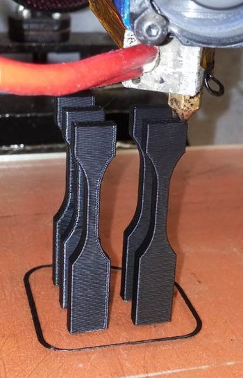
The most popular form of AM today is based on polymer extrusions. A fine filament polymer wire is fed into a heated nozzle and extruded into a thin bead (approximately 250–500 µm in diameter) to grow a part layer by layer. This technology, called fused deposition modeling (FDM), was pioneered by Stratasys, Inc. Today, more than 150 companies are manufacturing low-cost desktop printers using this technology. The most popular materials in these systems are variants of acrylonitrile butadiene styrene (ABS), which has a tensile yield stress of approximately 36 MPa and stiffness of 2.4 GPa (Stratasys ABS-M30). By comparison, Table I shows the in-plane (x-direction) and layer-to-layer (z-direction) bond strength for ABS tensile bars manufactured using various desktop printer platforms. In each case, the samples were printed with ABS with a slice height of 0.254 mm. Five sets of ASTM D638 Type V specimens, 5 oriented in the plane and z-direction, were populated on the corners and the center of the build platform (see Fig. 1).
Young's modulus and strength for in-plane samples (Ex, Sx) and vertically built samples (Ez, Sz).

Tensile bars being printed in the z-direction.

For each of these systems, the feedstock material was a 1.75 mm diameter ABS wire. The table shows that, with neat materials, there is significant variation in in-plane and z-strength between each of the existing desktop systems. Some systems, such as the Makerbot and CubeX, have closed source controllers, whereas other systems such as the Afinia and Solidoodle have open source controllers (which provide the ability to control temperatures, tool paths, and feed rates). Data show that the CubeX system has the highest in-plane strength but suffers in z-strength, whereas the Makerbot system approaches near isotropic mechanical properties.
The CF-reinforced ABS samples were prepared by compounding ABS pellets (GPS35-ABS-NT from M Holland Co, IL) with Chopped Hexcel AS4 CFs (epoxy sizing, 3.2 mm long) in a Brabender high-shear mixer at a temperature of 220 °C at 60 rpm until the torque remained constant. The compounded material was then extruded through a cylindrical die (1.75 mm diameter) at 220 °C using a plunger-type batch extrusion unit, composed of a steel barrel and cylindrical rod. Reference Tekinalp, Kunc, Velez-Garcia, Duty, Love, Naskar, Blue and Oscan6 Five sets of test specimens were manufactured on the same Solidoodle S3. The results in Table I show that the addition of 13% CF into ABS increases the strength by approximately 200% and modulus by 400% for in-plane samples. However, the z-strength dropped significantly, most likely because the filament did not conform to the underlying substrate as it was deposited, thus reducing the contact area between layers.
III. IMPACT OF CF ON GEOMETRIC TOLERANCES
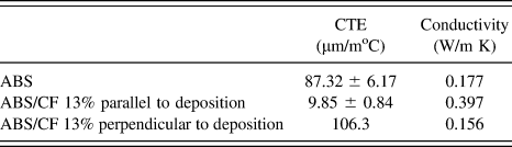
The previous section demonstrated the impact that the addition of CF has on the strength and stiffness when the fibers are compounded into the feedstock material. However, the addition of CFs also has a significant impact on the material's CTE as shown in Table II. CTE samples were measured both parallel and perpendicular to the deposition direction according to ASTM E228 using a TA TMA Q400 system. During the extrusion process, the CFs shear-align along the primary extrusion direction Reference Kunc, Velez-Garcia, Ozcan, Tekinalp, Lindhal, Love, Duty and Blue7 which changes the CTE by over an order of magnitude. Note that in the perpendicular direction, the CTE and conductivity values are very close to the neat ABS value.
CTE and thermal conductivity for ABS with and without CF reinforcement.
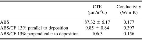
Reduced CTE and increased thermal conductivity have a profound impact on the geometric accuracy. Industrial AM systems deposit parts inside an oven, near the material's glass transition temperature. The motivation is to minimize thermal gradients that manifest as distortion of the part (curl and warp) in the final part. By increasing the thermal conductivity of the CF-reinforced material, thermal gradients are reduced throughout the part. Likewise, reducing the CTE minimizes the strain as the part cools from the deposition temperature (190–220 °C) to ambient conditions. The combination of these factors can significantly reduce the distortion of the part during manufacturing.
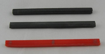
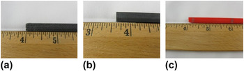
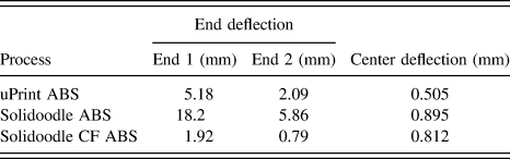
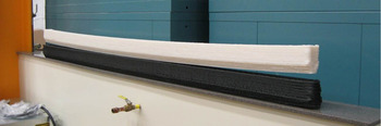
To illustrate the impact of material properties on the geometric distortion, three sets of prismatic bars were printed from different materials on different printing platforms. The samples were 102 mm long, 7.6 mm tall, and 5.0 mm wide with a 1.27 mm taper at the bottom (shown in Fig. 2). This “curl bar” specimen geometry has proved to be very sensitive to temperature gradients and the CTE of the material being deposited. One bar was printed with ABS in a Stratasys uPrint which has an oven that keeps the part near its glass temperature. The second bar was printed with ABS on a Solidoodle with a heated bed without an oven. The final part was manufactured with CF ABS (compounded as described above) on a Solidoodle with a heated bed. The objective was to quantify the impact the CF has on the final part geometry. Table III shows details of measurements on the bars indicating significant reduction in thermal distortion due to the presence of CFs. The end deflection was measured by clamping at 3.2 mm from the end of the curl bar and measuring the distortion at the opposite end. The center deflection was measured by clamping both ends of the bar to a straight edge and measuring the distance from the straight edge to the center of the bar.
Curl bars (CF ABS top, uPrint ABS middle, Solidoodle ABS bottom).

Distortion at the end of a curl bar printed on Solidoodle S3 with CF-reinforced ABS (left), uPrint with ABS (middle), and Solidoodle 3 with ABS (right).

Part deviation for curl bars printed on various platforms.
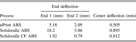
The impact of these results is profound. The CF-reinforced sample demonstrated significantly less distortion at the ends than either of the unreinforced ABS samples. This means that the addition of CF not only increases the strength and stiffness of the material but also may eliminate the need to carefully control the ambient temperature by depositing components in an oven. Out-of-oven AM significantly reduces the energy requirements and lowers the barrier for the integration of other components (such as batteries, sensors, electronics, etc.) into the parts during manufacturing. From an energy perspective, the uPrint (with an oven) consumes approximately 80 MJ/kg of energy during the manufacture of parts, whereas the desktop printers consume only about 20 MJ/kg.
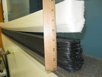
To further demonstrate the ability of CF-containing materials to enable innovation, we printed similar “curl bars” on ORNL's large-scale (2.5 × 2.5 × 2.5 m) out-of-the-oven polymer AM system. The curl bar model used for this system was 1.83 m long, 0.1 m tall, and 0.05 m wide (see Figs. 4 and 5). This system uses pellets, rather than a filament, as the feedstock material. For this demonstration, the same geometry was deposited using neat ABS (SD-0150 W from Cheil Industries) and 13% CF-filled ABS (Stat-Tech AS-13CF/000 from PolyOne) materials. Without the addition of CF, the ABS sample curls by approximately 25 mm on both sides, whereas the CF-filled sample shows distortion as illustrated in Fig. 5.
1.83 m long curl bars (ABS top, ABS/CF 13% bottom).

Curl measured near the end of the ABS/CF 13% bar (bottom – negligible) and ABS (top – approximately 25 mm).

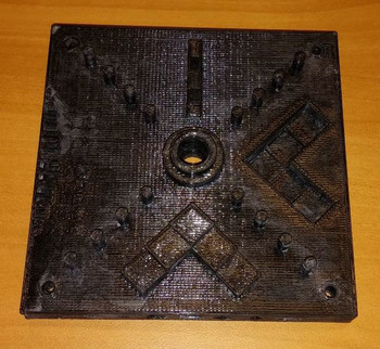
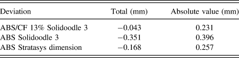
To further validate the differences in distortion on more complex geometry, NIST test articles Reference Moylan, Slotwinski, Cooke, Jurrens and Donmez8 shown in Fig. 6 were evaluated by comparing point cloud data from a Faro laser scanner 9 against the reference CAD model. The best-fit alignment was obtained between the measured and reference data with dimensional analysis software, 10 which provided a measure of the total and absolute value deviations. The geometric deviations were averaged over four sections near the edges of each sample to evaluate warping of the plate and are summarized in Table IV.
FDM-printed NIST test article.

Total and absolute value deviations measured on NIST article.
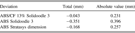
The total value, calculated as the sum of all the measured deviations, shows that the samples are smaller in size than the reference CAD model, and that printing with CF-reinforced material results in the least reduction in size. The absolute value, calculated by summing the absolute values of deviations, reveals that the precision of printing is comparable for all three samples. The CF-reinforced article demonstrated similar dimensional accuracy when compared with the article printed in the oven (using the dimension build platform) and significantly better accuracy than the article printed out of the oven (ABS Solidoodle 3).
IV. DEVELOPMENT OF HYBRID STRUCTURES
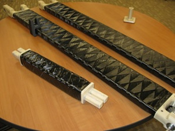
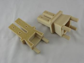
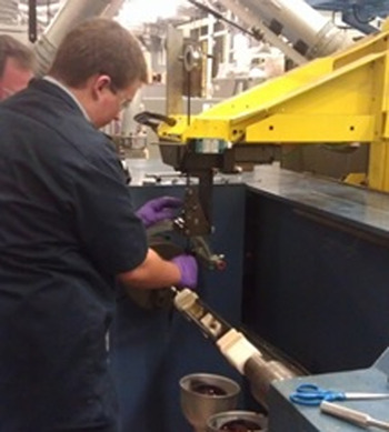
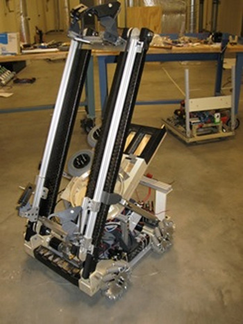
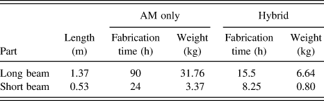
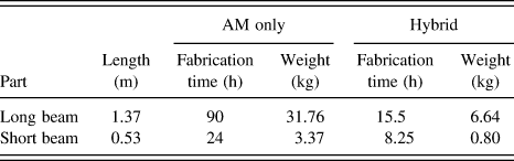
Additive processes excel at manufacturing very complex parts but are relatively slow (typically on the order of 15–80 cm3/h). CF composite structures are very lightweight but remain relatively simple structures. Combining these two technologies can enable the development of structures that leverage the strengths of each technology to produce both a complex and strong component. We have demonstrated this approach for the manufacture of lightweight beam structures with complex end couplings used for a robotic application (see Fig. 7). Rather than printing the entire structure, the complex end pieces were designed and manufactured with polymer AM systems, while the long slender sections of the structure were wound with continuous CF filaments. The unique design of the AM components allows for a complex geometric interface with the parent structure – in this case, coupling to a motor and bearing assembly – as well as providing a framework for the winding of the CF. The interface with the CF shell used tapered ends (38 mm long with 15° taper) that provided mechanical strength even if the bond between the polymer and CF were to fail (see Fig. 8). The design also incorporated fittings that interface with the CF tubes that formed a mandrel for winding the CF tow on to the final part (see Fig. 9). The polymer AM end pieces can either be solid or sparse filled (Fig. 8), depending upon the strength and weight requirements of the design. A sparse fill (such as an open honeycomb structure) reduced the weight of each printed part by more than 50%, from 0.25 to 0.11 kg. Table V compares the weight and manufacturing time for these parts if they were manufactured solely with AM, versus a hybrid additive/CF-winding approach described earlier. For the overall structure, the manufacturing time and weight were reduced by approximately 4x.
Long beams and AM end pieces.

AM end pieces.

Fiber winding.

Hybrid robot.

Additive versus hybrid manufacturing of beam structures.
V. SUMMARY
The merging of AM technology with CF composites holds great promise for improved strength, weight, and accuracy of manufactured components. This paper demonstrated that blending CF with polymer feedstock for polymer AM significantly increases the strength and stiffness of the final parts. It was also demonstrated that the addition of CF increased the thermal conductivity, decreased the CTE, and greatly reduced the distortion of the parts, enabling room temperature AM. Finally, the advantages of combining AM technology with continuous CF winding were illustrated for simple beam structures, greatly reducing the part weight and the manufacturing time without impacting the strength.