1. INTRODUCTION
The Radio-Technical Commission for Aeronautics (RTCA) (2002) defines ADS-B as a functionality, on an aircraft or a surface vehicle operating within the surface movement area, that periodically broadcasts its state vector and other information without knowing the recipients and without expecting acknowledgements, as the system only supports one-way broadcasts. The ADS-B system architecture can be divided into two subsystems, “ADS-B OUT” and “ADS-B IN”. The International Civil Aviation Organization (ICAO) (2003a) defines the term “ADS-B OUT” as the broadcast of ADS-B transmissions from the aircraft, without the installation of complementary receiving equipment to process and display ADS-B data on cockpit displays. The complementary subsystem is defined as “ADS-B IN”, which provides air-air situational awareness to the pilots. ADS-B OUT has the capability to operate independently to provide air-ground situational awareness to the ATC. The implementation of ADS-B IN however requires fully operational ADS-B OUT as a pre-requisite, in addition to the certification of cockpit displays, aircrew training on the new interfaces on board and other activities which have a longer deployment schedule. Hence ADS-B OUT must be fully deployed prior to ADS-B IN.
ADS-B is the key enabler for EUROCONTROL's Single European Sky Air Traffic Management (ATM) Research (SESAR) and the Federal Aviation Administration's (FAA) Next Generation Air Traffic Management (NextGen) modernization programs. These aim to improve airspace capacity and safety without jeopardizing the environment. To use ADS-B for aviation surveillance, the ICAO, in collaboration with the RTCA, Air Services Australia, FAA and EUROCONTROL stipulated various performance standards; Minimum Aviation System Performance Standards For Automatic Dependant Surveillance Broadcast (RTCA, 2002), Minimum Operational Performance Standards for 1090 MHz Extended Squitter Automatic Dependent Surveillance (RTCA, 2011) and Surveillance Performance and Interoperability Implementing Rule (EUROCONTROL, 2011b). These standards include requirements for aircraft equipage, ground infrastructure and required performance levels (i.e. accuracy, integrity, update-rate, availability and reliability) for the different phases of flight.
Integrity is a crucial parameter to measure system safety. Integrity is defined as the “level of trust that errors will be correctly detected while integrity risk is the probability that an error larger than a given threshold goes undetected for longer than a specified time to alert” (ICAO, 2006a). More specifically, ADS-B position integrity can be defined as the level of trust in the navigation source and the communication system to provide the required input to the ADS-B reported information. The navigation source integrity level is represented by the integrity quality indicator derived from the navigation system, included in the ADS-B message. Therefore, the safety of ADS-B depends on the navigation and communication systems.
According to Bhatti and Ochieng (Reference Bhatti and Ochieng2007), failures can occur from the system components, operational environment and human factors. It is important to note that, for ADS-B, the analysis of failure modes should include failures of the system-specific components and also of the integrated architecture that defines the whole system. Prior research has characterised failure modes for ADS-B-based applications (Hammer et al., Reference Hammer, Calgaris and Llobet2007, Walala, Reference Walala2008). However, it has not addressed failure modes of the ADS-B system as a whole. Hammer et al. (Reference Hammer, Calgaris and Llobet2007) provide a method for the analysis of ADS-B based on operational hazard identification and assessment. This method identifies potential hazards and allocates safety requirements to ADS-B ground and airborne functions. However, it is at a relatively high level of detail dealing with systems and applications, and does not address the failure modes of the ADS-B at the component level. Walala (Reference Walala2008) assesses the implementation of ADS-B for ground operations at non-towered airports to prevent runway incursions. The author identifies functional and general component failures that may potentially lead to runway incursion. Walala's (Reference Walala2008) approach focuses just on the ADS-B failures that lead to only a particular type of incident i.e. runway incursion. Neither study addresses ADS-B failure modes that will impact the system performance (particularly integrity and hence safety) for both ground and airborne applications. The next sub-section describes the various safety cases developed by EUROCONTROL, NATS, FAA and AirServices Australia for the ADS-B system. These are used in this paper to identify potential ADS-B failure modes.
1.1. Existing safety cases for ADS-B
EUROCONTROL has implemented preliminary safety cases for the ADS-B system in radar and non-radar airspace under the CASCADE programme. The programme coordinates the deployment of initial ADS-B applications in Europe. The programme covers both ground surveillance (i.e. “ADS-B OUT”) as well as airborne surveillance applications (i.e. “ADS-B IN”/Air Traffic Situational Awareness (ATSAW)). The key deliverables of the CASCADE programme are: standardisation, certification and integration support for the applications as well as airborne and ground-based system components; safety case activities; validation of ADS-B applications and systems; functional performance analysis and, as necessary, support to the rectification of system anomalies. In the context of the CASCADE program, a Preliminary Safety Case (PSC) does not include implementation, transition and in-service related issues. It includes design stages of the intended system, related requirements considering typical operating environment characteristics such as traffic density and separation minima to be applied. The various PSC relevant to this work are:
▪ PSC for ADS-B in Non Radar Area (NRA) (EUROCONTROL, 2008)
▪ PSC for ADS-B in Radar Area (RAD) (EUROCONTROL, 2010)
▪ Review of PSC for ADS-B in Radar Area (RAD) (Eurocontrol Safety Regulation Commission 2011)
▪ PSC for ADS-B in Airport Surface Surveillance (APT) (EUROCONTROL, 2011a)
Airservices Australia has conducted an operational trial of ADS-B for ATC surveillance in the Burnett Basin of Queensland. The safety case design and implementation has been developed based on a comparison of ADS-B to radar performance (ICAO, 2006a). The findings on the comparison study for ADS-B and SSR conducted by Airservices Australia indicates that ADS-B tracks are solid and without any significant multipath problems or gaps. The study also highlighted that ADS-B coverage is very close to that of radar. The minor differences identified are due to the antenna heights. In addition, the study also found that one particular aircraft was using ADS-B in excess of 360 nautical miles (nm). According to Airservices Australia if it is agreed that if ADS-B can be demonstrated to be as good as radar in the relevant system performance measures, then it can be used to deliver the services that radar currently supports. In December 2009, Airservices Australia commissioned the ADS-B Upper Airspace Project (UAP), providing ADS-B coverage across the whole continent. Since then, 29 ADS-B sites have been added, in addition to 14 sites in Tasmania that are now fully operational. Aircraft avionics are being assessed and approved for operational use. ADS-B data from non-approved aircraft is filtered out at each site. Currently, over 1200 aircraft are approved and receiving the operational and safety benefits of ADS-B services in Australia. Australia has also made ADS-B equipage mandatory for all aircraft (domestic and foreign) operating at or above FL290 as of December 2013 (SKYbrary, 2013).
ICAO has designed a generic safety case based on a safety case conducted by Airservices Australia on the operational use of ADS-B in non-radar airspace (ICAO, 2003b). The safety case is based on the reference system approach (ICAO, 1998).
The Federal Aviation Administration (FAA) has conducted a number of trials in non-radar areas such as the Capstone project in Alaska. The Capstone project was designed to identify safety and efficiency by ADS-B technology in Alaska and to demonstrate its capabilities for use nationally. Alaska was chosen as the test-bed due to its reliance on air transport more than other states, whereby only 10% of the state is accessible by road. In addition, Alaska contributes 35% of the nation's air transport accidents due to the state's mountainous terrain and extreme winter climate. A study by MITRE and the University of Alaska found that from 2000 to 2004, the rate of accidents for ADS-B-equipped aircraft was reduced by 47% (Federal Aviation Administration, 2011). Therefore the Capstone project has demonstrated that ADS-B would improve aviation safety in Alaska. Other trials for ADS-B demonstration are also being conducted in Philadelphia and in the Gulf of Mexico, where the traffic has grown at twice the rate in domestic airspace over the last decade (Esler, Reference Esler2007). Radar coverage is not possible over the Gulf of Mexico due to its geographical structure. However, air traffic in the Gulf is approximately as busy as the traffic in the East Coast Corridor, with 5000 to 9000 offshore platform helicopter operations daily and commercial flights between the US, Mexico, and South America. Low altitude aircraft are isolated and high altitude commercial aircraft are separated by 100 nm to ensure safety due to unavailability of radar surveillance, lack of communication and weather information. This leads to restricted capacity and inefficiency (Federal Aviation Administration, 2011). Initial ADS-B surveillance in the Gulf began in December 2009. This enabled controllers to separate high-altitude ADS-B-equipped aircraft over the Gulf, reducing the 100 nm separation to 5 nm in the trial. This also enabled low altitude helicopters to receive air traffic services and weather information. The trial has demonstrated significant improvement in the aviation operation in the Gulf. However, in August 2010, an 11 hour ADS-B outage due to failure of the ground station network without any backup affected air traffic control over the Gulf. The outage also affected the FAA's Surveillance Broadcast Services (SBS) which was intended to monitor the ground station performance (Office of Inspector General, 2011).
Apart from that, the FAA, in collaboration with UPS Corporation, conducted ADS-B terminal area proof of concept at the freight carrier's hub in Louisville. This trial was intended to increase airport capacity and address runway incursions at the busy cargo hub (Esler, Reference Esler2007).
Based on the various safety case reports reviewed, a number of failure modes for ADS-B were identified and are further analysed in this paper.
This paper conducts an exhaustive search for potential failure modes that can affect ADS-B performance using an approach developed in this paper (described in Section 2). The approach further guides the analysis of the impact of the failure modes to ATC operations and aircraft navigation based on the assumption that ADS-B operates as the sole surveillance source. Finally the identified failure modes are mapped to its corresponding mathematical model based on the failure mode characteristics.
2. ADS-B FAILURE MODE IDENTIFICATION APPROACH
A failure mode is a description of a state that disables the ability to perform a required function due to a certain event (Rausand and Høyland, Reference Rausand and Høyland2004). Due to the complexity and safety critical nature of the ADS-B system, a failure mode identification approach is developed in this paper for the system. The approach focuses on identifying possible failures in the system-specific components and its interaction and integration with external systems (eg. navigation and communication) and external elements such as human (controllers and pilots) and environmental factors. The approach is complex due to the different nature of the elements that compose the overall ADS-B system. The human element is identified as one of the failure modes for the ADS-B system. For instance, failures induced by a pilot's action (or inactions) may result in the loss of the ADS-B service to controllers on the ground for ATC operations without any alert. Such failures are analysed based on the outcome of the human actions to the overall system performance. The existence of elements with unpredictable natures increases the complexity of the system in addition to its highly integrated nature.
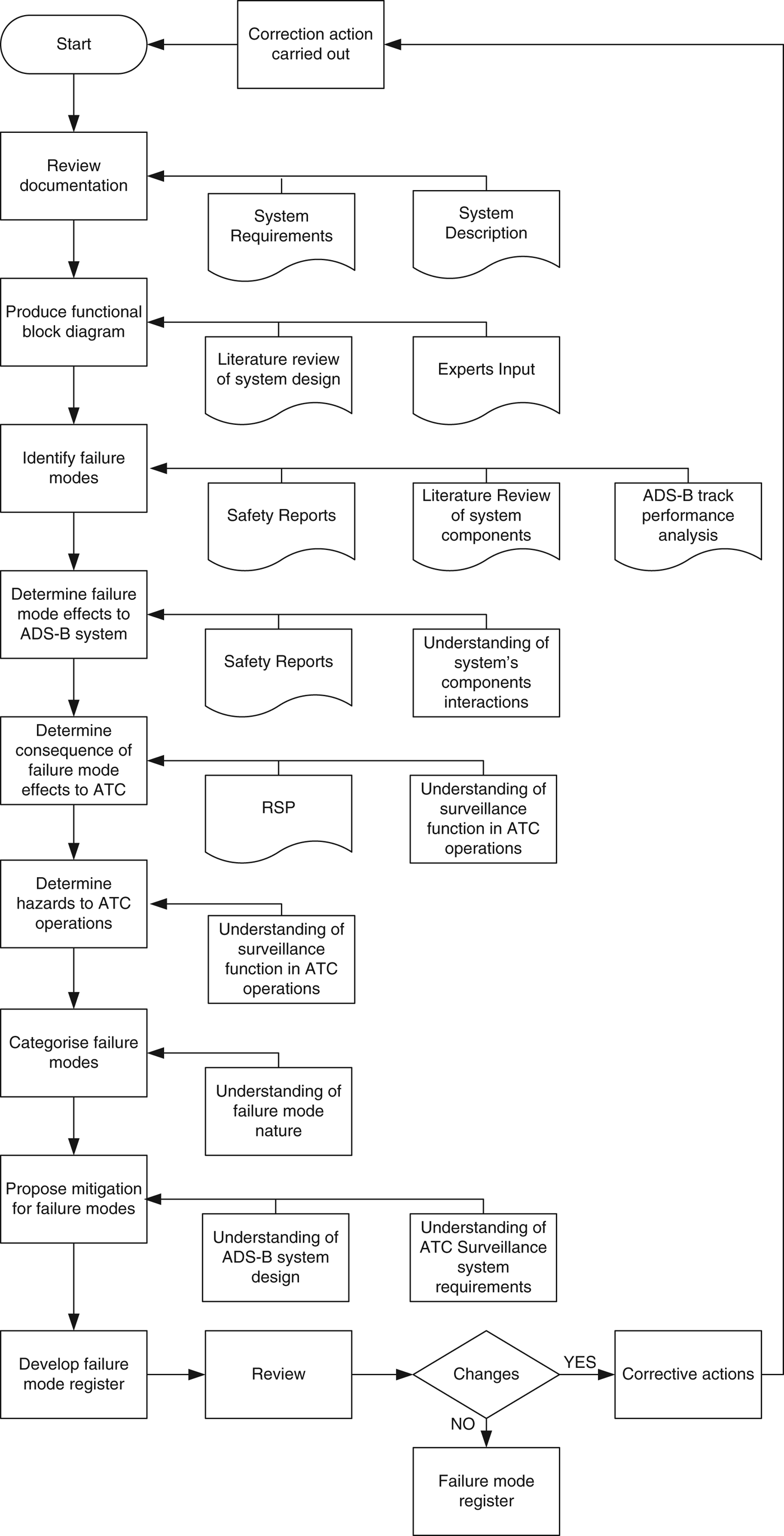
The failure identification approach is illustrated in Figure 1. The process comprises the following tasks:
▪ identify potential failure modes of the ADS-B system;
▪ identify failure mode effects on the ADS-B system;
▪ determine consequences of the failure effect on the overall ATC surveillance operations;
▪ determine failure hazards to ATC operations and aircraft navigation;
▪ categorise failure modes; and
▪ propose a mitigation approach for each failure mode.
ADS-B failure mode identification approach.

The input for the processes is obtained from:
▪ extensive literature review on each ADS-B specific component and the integrated navigation and communication system components;
▪ review of safety reports on ADS-B trials from various Air Navigation Service Providers (ANSPs) worldwide including EUROCONTROL, FAA and Air Services Australia;
▪ analysis of ADS-B reports gathered from ADS-B ground stations and corresponding positioning data from on board navigation system (Global Positioing System - GPS) for 37 aircraft through collaboration with NATS CRISTAL Project and British Airways;
▪ input from Subject Matter Experts (with more than five years of experience on ADS-B system design and trial implementation) from EUROCONTROL, QinetiQ, Airbus and NATS via structured interviews; and
▪ authors' understanding of the overall system architecture and functionalities.
The next section describes the processes, input used and output in detail.
2.1. ADS-B Failure Identification Process
In the first step, various technical documents of the ADS-B system requirements and system descriptions are reviewed to gain a comprehensive understanding of the system architecture, functionalities and operations.
In the second step, a high-level system architecture diagram (Figure 2), ADS-B OUT functional block diagram (Figure 3) and ADS-B IN functional block diagram (Figure 4) are developed based on input from a literature review and expert input (particularly from Airbus, NATS and British Airways). The system architecture in Figure 2 is divided into five levels: Level-0 indicates the Global Navigation Satellite System (GNSS) subsystem; Level-1 indicates ADS-B avionics, known as the on board ADS-B OUT subsystem; Level-2 indicates the ADS-B IN specific subsystem; Level-3 indicates the ADS-OUT ground station subsystem and Level-4 indicates the controller working positions on the ground. Figure 3 illustrates detailed components of the ADS-B OUT functional block composed of the Message Generation Function which obtains its input from external systems: on board navigation system, barometric altimeter, pilot interface and Flight Management System (FMS), and then encodes and assembles the message; and Transmit Message Exchange Function which broadcasts the ADS-B message to the users (other ADS-B-equipped aircraft and to ATC on the ground). Figure 4 illustrates detailed components of the ADS-B IN functional block composed of Receive Message Exchange Function, which receives the encoded message from Transmits Message Exchange Function (Figure 3); and Report Assembly Function which decodes and feeds the ADS-B message to Client applications: FMS, Traffic Collision Avoidance System (TCAS), Airborne Separation Assistance System (ASAS) and Cockpit Display of Traffic Information (CDTI) for aircraft navigation aids.
ADS-B High Level System Architecture.
ADS-B OUT Functional Block Diagram.
ADS-B IN Functional Block Diagram. * shaded boxes indicate software modules.
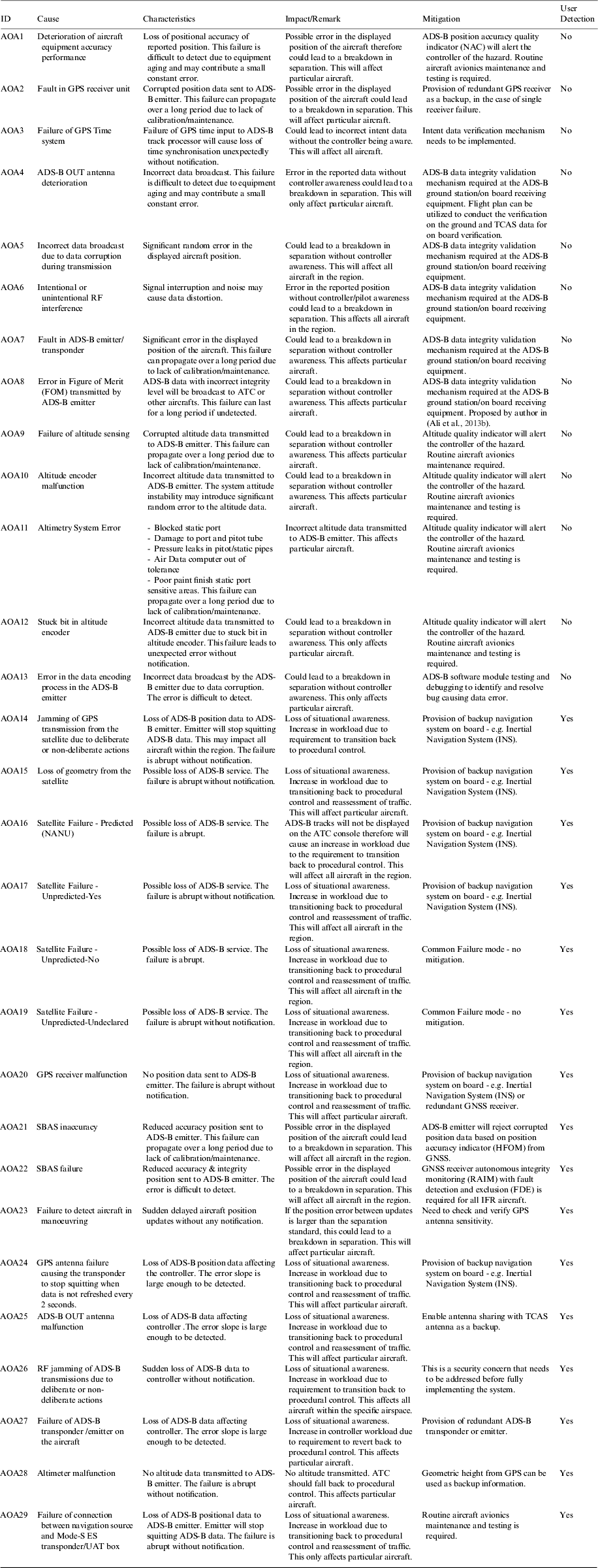
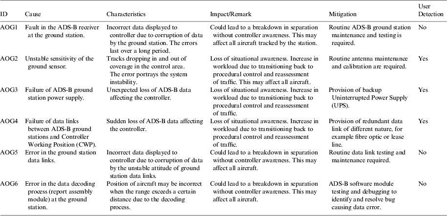
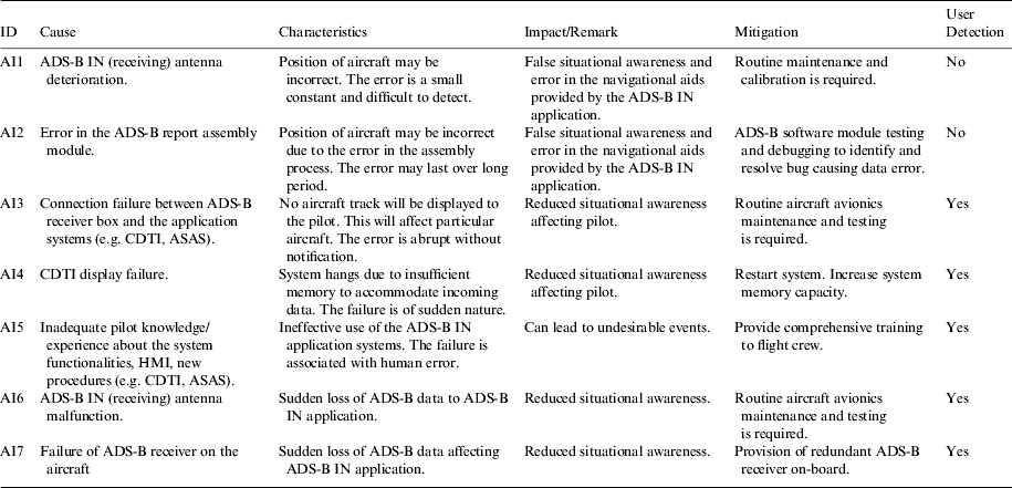
In the third step, ADS-B failure modes are identified from safety reports by ANSPs on ADS-B trial implementations, an extensive literature review on the system components and ADS-B report performance analysis. For further details of the ADS-B report performance analysis, refer to (Ali et al., Reference Ali, Schuster, Ochieng and Majumdar2013c, Ali et al., Reference Ali, Majumdar, Ochieng and Schuster2013a) Reference Ali, Majumdar, Ochieng and Schuster2013a). The scope of the analysis in this paper is from Level-0 to Level-4 as shown in Figure 2. Most of the failure modes in Level-0 (GNSS) included in the paper are adopted from existing research (Bhatti and Ochieng, Reference Bhatti and Ochieng2007, Ochieng and Sauer, Reference Ochieng and Sauer2003, The Royal Academy of Engineering, 2011). Failures also result from interfaces between the components, human errors and environmental effects. The failure modes identified are provided in Tables 1 to 5.
ADS-B OUT avionics failure modes.
ADS-B OUT ground station failure modes.
ADS-B IN failure modes.
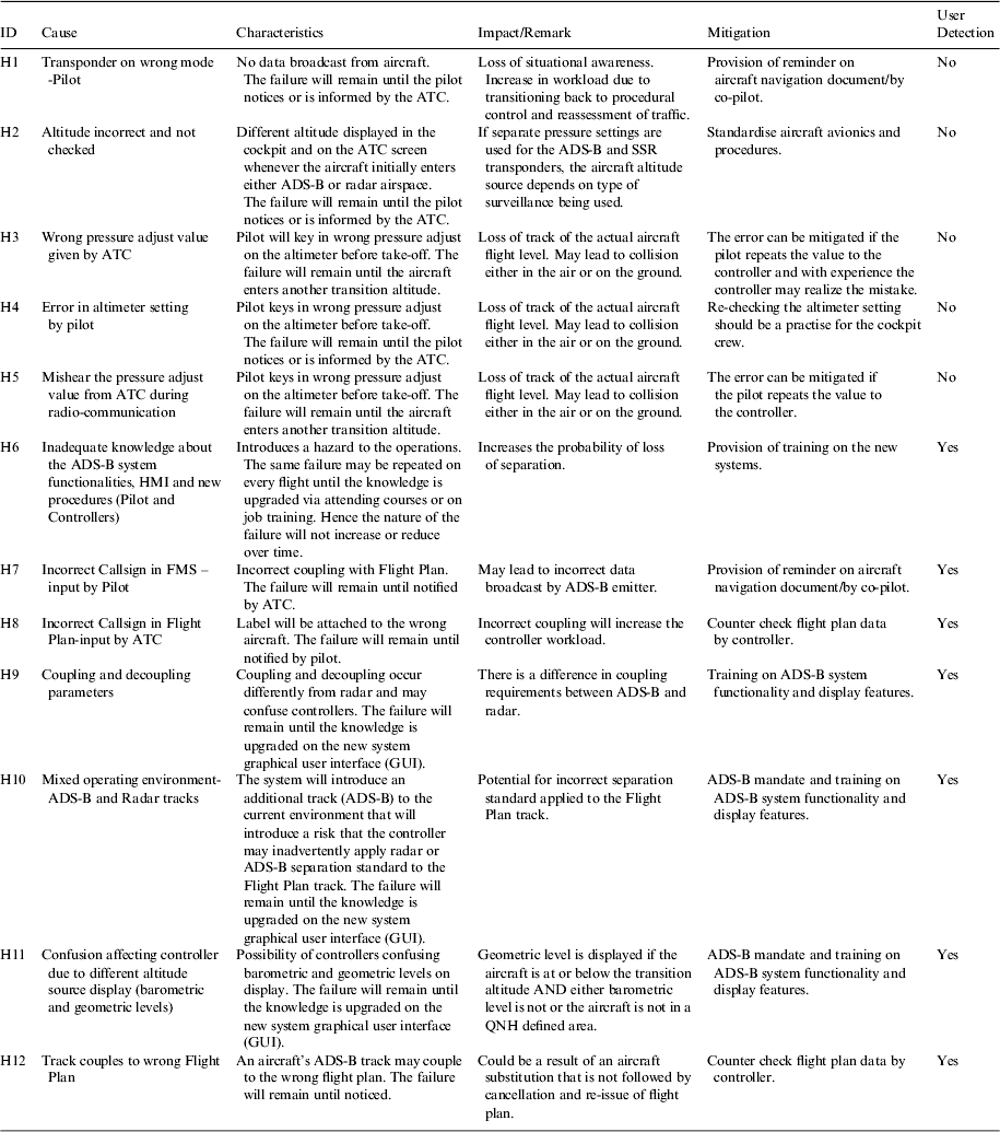
Human error.
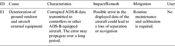
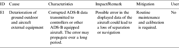
Environmental effects.
In the fourth step, the effects of each failure mode on the ADS-B system performance are analysed based on the safety reports and understanding of the system component interactions and functionalities.
In the fifth step, the consequence of the failure mode effects on ATC surveillance operations and aircraft navigation are analysed by referring to the Required Surveillance Performance (RSP) and understanding the required surveillance function and level of performance for ATC operations.
In the sixth step, specific hazards to ATC operations are also determined due to the failures based on the required surveillance functions.
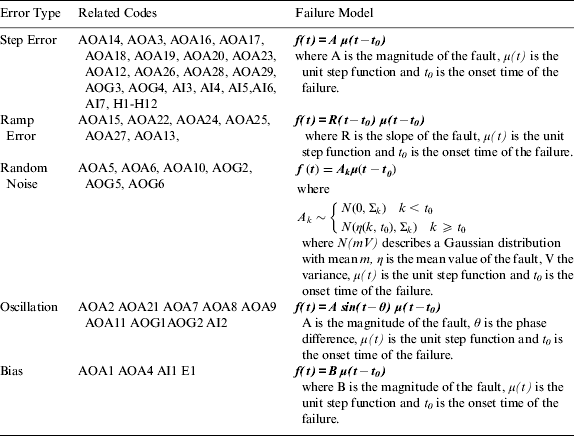
In the seventh step, the characteristics of each failure mode are described and categorised based on the failure model: step error, ramp error, random noise, oscillation, or bias error by understanding the nature of the failure modes.
In the eighth step, mitigation for each failure mode identified is derived/proposed based on the understanding of the ADS-B system design and ATC surveillance system requirements.
In the last step, the list of identified failure modes is reviewed in an iterative manner to revise and update the failure mode register. The failure mode register is a living document that can be updated as more failures are discovered in the future.
3. ADS-B FAILURE MODES
ADS-B is a complex system dependent on external systems, including navigation, communication and users. These systems are integrated to ADS-B-specific components to build the complete system i.e. ADS-B OUT and ADS-B IN sub-systems. There is potential for failure at any one of a number of stages from production of aircraft state vector data (navigation system), upload and processing in the ADS-B on board components, to their transmission (Figure 3), reception (Figure 4) and processing at the ADS-B ground station for ATC use.
Failure modes for each component in Figures 2, 3 and 4 are identified for ADS-B OUT avionics, ADS-B OUT ground stations, ADS-B IN, the human element and failures resulting from environmental effects, as shown in Tables 1 to 5 respectively. The tables provide lists of ADS-B failure modes captured from existing literature, and augmented with new modes identified in this paper. Each failure mode is assigned a unique identification (ID). The ID is used later in the paper to facilitate grouping of failure modes, so that error type models can be specified for each group as shown in Table 6. In the second column of the tables, causes of the failures are described. This is followed by a description of the failure characteristics based on the actual surveillance data performance and the nature of its occurrences (component level). The next column provides the failure impact on the relevant ATC or aircraft navigation operations (functional level) based on the observable ADS-B surveillance data presented to the users. The nature of the impact is characterised by the type of the failure identified in Table 6. Impacts due to each error type are described in Section 4. Column five proposes mitigation measures for each failure in the next column. The mitigations are proposed based on the understanding of the ADS-B functionalities and architecture (obtained from literature, expert input and ADS-B data analysis, collected from NATS UK ADS-B ground stations under the CRISTAL UK project (NATS, 2011). The last column determines user capability to detect the failure modes in terms of the observable manifestation of the failures. The failure detectability is determined based on the failure characteristics in column two. The degree of the detectability is also influenced by the failure type. This is explained in detail in Section 4 for each failure type.
Failure mode classification, groups and models.
4. FAILURE MODELS
To assess the system integrity performance, the failure modes are modelled mathematically. The first step in the modelling process is to analyse the error type based on the failure mode characteristics in the third column of Tables 1 to 5. The second step is to group the failure modes based on the error nature; the error groups are then mapped to their corresponding mathematical function. Table 6 summarises the failure mode classification based on the error type and corresponding failure model. The error type classification is adopted from Bhatti and Ochieng (Reference Bhatti and Ochieng2007) on the classification of GPS and INS failure modes. This classification approach is adopted for the work in this thesis, for two main reasons: the characteristics of ADS-B system failure modes are found to be similar to the GPS failure modes; and the GPS system feeds the ADS-B system with the aircraft positioning information; and hence contributes to the ADS-B failures. Based on the failure mode analysis, five types of errors were identified: step, ramp, random noise, oscillation and bias. A description of each error type including nature of the occurrence and possible causes are given in Figure 5.
ADS-B error types.
5. DISCUSSION
The main novelties in this paper are a comprehensive failure mode register for ADS-B and an approach for ADS-B failure mode identification. The failure mode register is a living document that can be populated to assist system maintenance; docket logging and most importantly to support incident investigations. The approach includes various types of data sources including literature, safety reports, subject matter expert input and ADS-B track analysis. In addition, it also takes into account failure modes induced by the human element and environmental factors.
Based on the findings in this paper, a safety advantage of ADS-B over the radar system is that there is the potential for coverage in those areas that currently lack radar coverage. This assumes that GNSS meets the required performance, as the ADS-B relies on it. Failure to meet the requirements (e.g. due to satellite or ionospheric induced failures) presents the problem of a single point of failure capable of affecting ATC surveillance over a given region. Research is underway to address these types of GNSS vulnerabilities to develop effective mitigation measures. Furthermore, it is also important to note that the largest risk in GPS-based positioning is actually GPS nominal performance (i.e. accuracy issues rather than integrity). The tail errors of GPS pose a more serious problem for approach and surface operations than many of the failure modes. In addition, the availability of several ADS-B ground stations reduces the probability of failure of ground-based ADS-B systems to capture ADS-B data from aircraft. On the other hand, a radar system failure in the regions that lack coverage redundancy would cause a complete surveillance breakdown. This would force controllers and flight crew to engage in procedural control for ATC operations (ICAO, 2007; 2006b) for all aircraft within the sector.
The findings indicate that some of the failure modes only affect one aircraft. However, loss of ADS-B data from one aircraft will impact the reliability of airborne applications such as ASAS, CDTI and various other future air navigation applications, such as situational awareness, conflict detection, conflict resolution, separation assistance or trajectory prediction. In the cases where the failure modes are not detected, this may lead to safety risks. The degree of failure detectability is dependent on the failure type. Ramp error is most difficult to detect when the error slope is small. Most of the errors categorised under this error are found to be undetectable by the users. Step error that includes human error is also difficult to detect e.g. failures HI-H5 in Table 5. Mitigations proposed in Tables 1 to 5 address how these can be resolved according to the specific failure modes.
The ADS-B failure mode register is not limited to that developed in this study. It is expandable based on daily ADS-B operational experiences by ANSPs or airline operators. The mitigations proposed in this paper are not tested in real time operations. It is solely developed based on the authors' understanding of the ADS-B system functions, architecture and ATC system operations; and input from experts. Therefore it should be tested by ANSPs and airline operators. The use of the register also depends on the architecture of the surveillance system in the ANSP's operational environment. The register developed in this paper is based on the assumption that ADS-B is operating as the sole surveillance system. Hence, some of the failure modes may be complemented with the supplemental surveillance system where they exist.
6. CONCLUSION
This paper has presented the potential failure modes of the ADS-B system. The results include description of the failure mode occurrence causes, failure characteristics and their impacts affecting ATC operations and aircraft navigation. In addition, potential mitigation for each failure is proposed and the capability of the users to detect the failures is also determined. Finally, the failure modes are grouped into specific error types and the failure model for each group is presented. The contribution in this paper is relevant for the safety assessment of the ADS-B system implementation by the ANSPs and also airline operators. It is also applicable for post implementation activities that include system maintenance, failure troubleshooting and incident investigation due to the failure of the surveillance system. The mathematical models for the failure mode classes are crucial for developing techniques or mechanisms for failure detection, identification, exclusions or even potentially correction. Future work will build on these models to develop measures to mitigate failures that arise to improve ADS-B system availability. It should be noted also that this paper has focused on the identification and impact analysis of ADS-B specific failures. Future work will identify and analyse failure modes that arise from the integration of the ADS-B system with other independent systems such as safety nets, radar and multi-lateration.