

1. Introduction: imaging biological specimens
Fluorescence optical microscopy is an ideal tool in life sciences for imaging biological specimens and in particular, for live-cell and live-tissue imaging. Complex and dynamic intracellular interactions are visualized with a high degree of specificity. Visualization of fluorescent biological specimens is initiated by illumination. The excitation light from the illumination source invades into the specimen and interacts with fluorescent probes to generate a fluorescence response that is captured by a detector (or camera). The extent of interaction between the excitation light and the fluorescent specimen governs two important outcomes in the imaging process, ‘image quality’ and ‘photodamage’ (Ettinger & Wittmann, Reference Ettinger and Wittmann2014; Hoebe, Reference Hoebe2010; Ji et al. Reference Ji, Shroff, Zhong and Betzig2008; Stephens & Allan, Reference Stephens and Allan2003). Image quality is dictated by the measure of the captured fluorescence response, which is inferred quantitatively by the signal-to-noise ratio (SNR) of the image, whereas photodamage is one of the major limiting factors in fluorescence imaging (Bernas et al. Reference Bernas, Zarebski, Cook and Dobrucki2004; Dixit & Cyr, Reference Dixit and Cyr2003; Ji et al. Reference Ji, Shroff, Zhong and Betzig2008; Stephens & Allan, Reference Stephens and Allan2003). Photodamage is caused by the phenomena ‘phototoxicity’ and ‘photobleaching’. Phototoxicity damages life specimen by inducing toxic radicals such as reactive oxygen species when the fluorescent specimen interacts with the excitation light (Grzelak et al. Reference Grzelak, Rychlik and Bartosz2001; Magidson & Khodjakov, Reference Magidson and Khodjakov2013). Photobleaching is excitation light-induced degradation of the fluorescent probes that leads to a decreased fluorescence response and eventually no response (Magidson & Khodjakov, Reference Magidson and Khodjakov2013). Both phototoxicity and photobleaching disturb the microenvironment of the fluorescent specimen, which severely restricts the imaging process, by reducing its biological relevance (Ji et al. Reference Ji, Shroff, Zhong and Betzig2008; Khodjakov & Rieder, Reference Khodjakov and Rieder2006; Magidson & Khodjakov, Reference Magidson and Khodjakov2013; Stephens & Allan, Reference Stephens and Allan2003).
Several strategies have been developed to minimize photodamage, such as selection of fluorescent probes with high photostability, controlling the microenvironment of the biological specimen, optimization of the microscope to avoid out-of-focus illumination, which increases the risk of photodamage (Huisken et al. Reference Huisken, Swoger, Del Bene, Wittbrodt and Stelzer2004; Magidson & Khodjakov, Reference Magidson and Khodjakov2013; Marx, Reference Marx2015; Schilling et al. Reference Schilling, Frank, Magidson, Wason, Lončarek, Boyer, Wen and Khodjakov2012; Stephens & Allan, Reference Stephens and Allan2003; Waterman-Storer et al. Reference Waterman-Storer, Desai, Bulinski and Salmon1998). However, the extent of the effects of photodamage on image quality largely depends on the light dose used for illumination (Carlton et al. Reference Carlton, Boulanger, Kervrann, Sibarita, Salamero, Gordon-Messer, Bressan, Haber, Haase, Shao and Winoto2010; Khodjakov & Rieder, Reference Khodjakov and Rieder2006). The illumination light dose is a combination of light intensity and exposure time. When a high light dose is used for illumination, it leads to high image quality (i.e. high SNR), but also increases photodamage. Researchers usually reduce the illumination light dose on the basis of experience, intuition or visual inspection during imaging to avoid photodamage. Photodamage may lead to unpredictable and unperceivable effects, which can either be subtle or more drastic to the extent, that they mask fast dynamic events or processes, or even lead to image artefacts (Carlton et al. Reference Carlton, Boulanger, Kervrann, Sibarita, Salamero, Gordon-Messer, Bressan, Haber, Haase, Shao and Winoto2010; Chuang et al. Reference Chuang, Carpenter, Fuchsova, Johnson, De Lanerolle and Belmont2006; Editorial Nature Methods, 2013; Harnett et al. Reference Harnett, Makara, Spruston, Kath and Magee2012; Mikhailov et al. Reference Mikhailov, Shinohara and Rieder2005; Uetake et al. Reference Uetake, Lončarek, Nordberg, English, La Terra, Khodjakov and Sluder2007; Williams et al. Reference Williams, Stap, Essers, Ponnaiya, Luijsterburg, Krawczyk, Ullrich, Aten and Bailey2007). However, solving these problems by the reduction of the excitation light-dose compromises image quality. It is never exactly known whether the correct balance between photodamage and image quality has been achieved. Controlled light exposure microscopy (CLEM) has been first developed to address this issue (Hoebe, Reference Hoebe2010; Hoebe et al. Reference Hoebe, Van Oven, Gadella, Dhonukshe, Van Noorden and Manders2007). Subsequently, a similar approach was implemented in active/adaptive illumination microscopy (AIM) (Chu et al. Reference Chu, Lim and Mertz2007, Reference Chu, Lim and Mertz2010). Both techniques employ real-time spatial control of illumination to achieve a good trade-off between image quality and photodamage. Conceptually, we refer to these techniques as ‘spatially-controlled illumination microscopy’ (SCIM). The present review discusses the concept and working principle of SCIM along with its applications in different types of optical microscopes.
2. Concept of SCIM
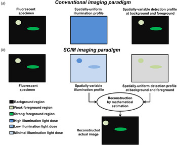
The principle of SCIM is based on spatial control of the illumination light dose, in such a way that photodamage is minimized without compromising image quality. Figure 1 illustrates this concept of SCIM in comparison with conventional optical microscopy. Conventionally, imaging is performed by using a spatially-uniform illumination light dose with spatially-variable detected signals, whereas SCIM uses a spatially-variable illumination light dose with spatially-uniform detected signals (Chu et al. Reference Chu, Lim and Mertz2007; Hoebe et al. Reference Hoebe, Van Oven, Gadella, Dhonukshe, Van Noorden and Manders2007). The details of spatial intensity distribution of the biological specimen (i.e., actual image information) are predominantly encoded in the variable illumination profile and not in the detection, as is the case in conventional imaging. SCIM aims for two different constant levels of signal in its detection. In the ‘foreground regions’, where there are fluorescence signals from the specimen, it aims for a fixed value as per the desired image quality (i.e. SNR). In the ‘background regions’, where fluorescence signals from the specimen are absent, a (near) zero detection is aimed for. SCIM is based on two different strategies,
-
(a) Foreground strategy (Turn ON illumination)
-
(b) Background strategy (Turn OFF illumination)
Concept of SCIM in comparison with conventional optical microscopy. (a) Conventional optical microscopy uses spatially-uniform illumination to acquire a variable detection. (b) SCIM aims at spatially-uniform detection profiles in the background and foreground regions in accordance with the desired SNR by adopting spatial control of illumination light dose. It ‘turns ON’ illumination with sufficient light dose in the foreground regions and ‘turns OFF’ or minimizes illumination in the background regions. The actual image containing spatial intensity information of the specimen is reconstructed with mathematical estimation techniques using the detection and illumination profiles.

2.1 Foreground strategy
This strategy is used in the foreground regions. Illumination is ‘turned ON’ in weakly fluorescent regions with a relatively higher light dose to obtain sufficient SNR for the desired image quality. In strongly fluorescent regions relatively lower light doses are sufficient to obtain the same SNR. In SCIM, unnecessary exposure of bright fluorescent regions of the specimen is thus avoided, and reduces photodamage as a consequence.
2.2 Background strategy
This strategy is used in the ‘background regions’. Illumination is ‘turned OFF’ with zero or minimal light dose. Although this strategy does not have a direct impact on the quality of the image, it yields a significant reduction of photodamage. This is because unnecessary excitation of fluorescence from out-of-focus points (or planes) is avoided by turning OFF the light, which in most cases otherwise extends to areas beyond the focal point (or planes).
2.3 Consequences of foreground and background strategies
Both foreground and background strategies lead to an illumination profile that is not spatially uniform over the entire fluorescent specimen. The actual image information is reconstructed using mathematical estimation based on the information from the detected image and the illumination profile (Fig. 1b ). Recovering the spatial intensity (or actual image) information of the biological specimen is thus transferred from the domain of detection to mathematics on the basis of the illumination profile. A linear interpolation-based reconstruction can be used by taking the ratio of the constant value detected and the illumination profile.
Mathematical reconstruction in SCIM allows for obtaining images with a high dynamic range (HDR). With constant detections, the dynamic range of the actual image is fundamentally not limited by the physical capabilities of the detector (or camera), but based on how precisely the illumination can be controlled. In practice, the tunable illumination sources offer excellent controllability. On the other hand, the detector needs to capture a pre-determined constant level of signals. Therefore, saturation of the detector (or camera) can be avoided completely, paving the way for the use of sensitive single photon detectors (or cameras) to detect ultra-weak signals (Krishnaswami et al. Reference Krishnaswami, Van Noorden, Manders and Hoebe2014). The use of sensitive detectors (or cameras) in combination with HDR increases imaging capabilities (Chu et al. Reference Chu, Lim and Mertz2007; Hoebe, Reference Hoebe2010; Hoebe et al. Reference Hoebe, Van Oven, Gadella, Dhonukshe, Van Noorden and Manders2007).
In conclusion, because the illumination levels are reduced in both background and foreground regions when variable illumination is applied, significant reduction of photodamage is realized. It paves the way for prolonged live-cell and live-tissue imaging with a large dynamic range.
3. Implementations
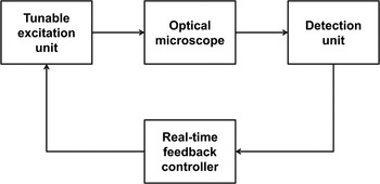
Realization of SCIM requires a fast hardware-based and/or firmware-based automated controller setup which performs real-time monitoring of detected signals and control of the illumination. The controller has to identify background and foreground regions with inputs from the detector (or camera) and has to be fast enough to control illumination light dose from a tunable source. This forms a closed-loop feedback system, with a real-time controller between the detection and excitation units as shown in Fig. 2. In practice, SCIM is an add-on solution between the detection and excitation units. SCIM has already been implemented in confocal, two-photon, wide-field and super-resolution microscopes. Here, we discuss the implementation of SCIM in various types of optical microscopes that are already in use for advanced live-cell and live-tissue imaging.
Closed-loop feedback system for spatial control of illumination in a SCIM setup.

3.1 Confocal laser scanning microscopy (CLSM)
CLSM is a single-point scanning technique where the illumination laser source is scanning point by point over the region of interest in the fluorescent specimen (Brakenhoff et al. Reference Brakenhoff, Blom and Barends1979). CLSM is based on a pinhole in front of the point detector that only allows the light from the focus point to be detected, while blocking light from the out-of-focus regions, thus providing optical sectioning. However, adopting point scanning techniques like CLSM requires a compromise between the scanning time and the illumination light dose, which is dictated by the fluorescence levels of the biological specimen (Croix et al. Reference Croix, Shand and Watkins2005).
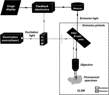
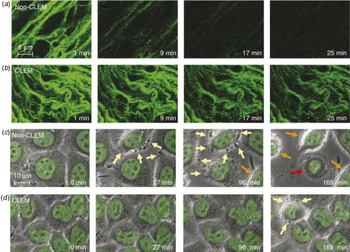
SCIM has been successfully implemented in CLSM and introduced as CLEM (Hoebe, Reference Hoebe2010; Hoebe et al. Reference Hoebe, Van Oven, Gadella, Dhonukshe, Van Noorden and Manders2007). Figure 3 depicts the schematic setup of SCIM in CLSM. The illumination control is performed by varying the time of exposure to the excitation light in both background and foreground regions. It employs an electronic circuitry for the controller unit in the feedback loop, between detection unit (point detector) and an acoustic-optical modulator (AOM), which acts as a shutter to vary the duration of illumination. The feedback electronics monitor the detected signals, during pixel (data) acquisition on a real-time basis. The detected signal levels are compared with the preset background and foreground threshold values to identify the profile of the region. In the case of a weak foreground region, illumination is made to last until the signal levels are equal to the preset ‘foreground threshold value’ selected on the basis of the desired SNR. For a strong foreground region, where the desired SNR is obtained after a brief exposure to the excitation light, illumination is immediately ‘turned OFF’ for the residual pixel exposure time. This completes the foreground strategy. The background strategy is based on the comparison of signal levels with a ‘background threshold value’ at the ‘background decision time’ which is a fraction of the total pixel dwell time. When at decision time the signal is still below the background threshold value, the illumination is ‘turned OFF’, thus preventing unnecessary exposure of background regions. The actual exposure time for every pixel is recorded to generate an illumination profile that is actually employed by the feedback controller unit. Based on the illumination profile, a linear extrapolation technique is used to determine the pixel intensity for the complete pixel dwell time, resulting in the spatial intensity (or image) information of the fluorescent biological specimen. This approach yields a 2–10-fold reduction of the effects of photodamage in addition to the inherent data compression and extended dynamic range (Hoebe, Reference Hoebe2010; Hoebe et al. Reference Hoebe, Van Oven, Gadella, Dhonukshe, Van Noorden and Manders2007). As a result, up to six times prolonged live-cell imaging was achieved (Fig. 4) (Hoebe et al. Reference Hoebe, Van Oven, Gadella, Dhonukshe, Van Noorden and Manders2007). The SCIM approach was, for example, applied to study organization and dynamics of telomeres (De Vos et al. Reference De Vos, Hoebe, Joss, Haffmans, Baatout, Van Oostveldt and Manders2009, Reference De Vos, Houben, Hoebe, Hennekam, Van Engelen, Manders, Ramaekers, Broers and Van Oostveldt2010).
Illustrative scheme of SCIM implementation in a CLSM. CLSM is a point-scanning imaging technique which employs a pinhole to enable optical sectioning. SCIM incorporates real-time monitoring and decision making at the pixel level, during acquisition with the help of feedback electronics. The feedback electronics then controls the AOM shutter to ‘turn ON’ and ‘turn OFF’ illumination to achieve spatial control of illumination light dose in background and foreground regions.

Time-lapse images comparing conventional imaging with SCIM implemented in a CLSM introduced as CLEM as reproduced from Hoebe et al. (Reference Hoebe, Van Oven, Gadella, Dhonukshe, Van Noorden and Manders2007). Scale bar in (a) & (b), 5 µm. Scale bar in (c) & (d), 10 µm. (a) Fluorescence imaging of 3D stacks of tobacco BY-2 cells expressing microtubule-associated GFP-MAP4 with spatially-uniform illumination results in photobleaching within 25 min. (b) Fluorescence imaging using spatially-controlled illumination, of tobacco BY-2 cells results in much lesser photobleaching and prolongs imaging. (c) Conventional time-lapse imaging of living H2B-GFP-expressing HeLa cells in which the GFP signal (indicated in green) is superimposed on the phase-contrast images (indicated in grey). Yellow arrows indicate blebbing of the membrane after 27 min of exposure. After 96 min, the rounding up of cells begins as indicated by the orange arrows and after 169 min some cells are apoptotic as indicated by the red arrow. (d) Phase-contrast imaging of live HeLa cells after using SCIM in CLSM shows reduced photodamage, which allows prolonged live-cell imaging by a factor 6.

3.2 Two-photon microscopy
Two-photon microscopy is a single-point scanning technique similar to CLSM, with the main difference being the mode of fluorescence excitation. Two photons with a lower energy level (longer wavelength) instead of a single photon with a higher energy level are used for the excitation of a single fluorescent probe (Helmchen & Denk, Reference Helmchen and Denk2005). Consequently, two-photon microscopy has the advantage of increased penetration depth into the biological specimen due to reduced scattering. However, two-photon excitation of fluorescent probes scales with the square of the power of the illumination source. Therefore, high-power illumination sources are used for imaging. This increases the risk of phototoxicity. It has to be noted that, whereas the photobleaching rate of a fluorescent probe is mainly determined by the level of illumination, phototoxicity depends on the total number of photons that are interacting with the fluorescent regions in the biological specimen (Chu et al. Reference Chu, Lim and Mertz2010). Therefore, despite lower per-photon energy, phototoxicity can still play a significant role in two-photon or multi-photon systems (Williams et al. Reference Williams, Stap, Essers, Ponnaiya, Luijsterburg, Krawczyk, Ullrich, Aten and Bailey2007).
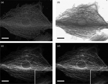
SCIM was used in two-photon microscopy to further reduce the risk of phototoxicity in AIM (Chu et al., Reference Chu, Lim and Mertz2007, Reference Chu, Lim and Mertz2010). Besides minimizing the risk of phototoxicity, AIM allows for enlargement of the dynamic range. AIM is based on an approach very similar to CLEM. The intensity of the illumination source is controlled by a feedback system between detection and excitation units. The feedback system uses a proportional-integral-derivate (PID) controller, which measures the difference between a set level (desired SNR) and the measured level of a signal. Depending on the difference between the set and detected levels, correction signals are issued to control the illumination source by adopting two regimes, the feedback-active (FA) regime and power-limited (PL) regime. The FA regime is applied to strong foreground regions and the light dose is controlled to obtain the desired SNR. On the other hand, the PL regime is applied to weak foreground regions and the light dose is set at significantly higher levels than in a typical two-photon microscope to extract information from weakly fluorescent regions, thereby enhancing sensitivity (Chu et al. Reference Chu, Lim and Mertz2007). The spatial intensity (or image) information is extracted by using the ratio of detected values and the square of the corresponding modulated light dose that was used. Reconstruction of the image in strongly fluorescent regions enables a higher dynamic range, avoiding saturated values that occur in two-photon microscopy. An improved performance with AIM was found in both weak-signal detection and dynamic range, in comparison with two-photon microscopy (Fig. 5) (Chu et al. Reference Chu, Lim and Mertz2007).
Imaging of bovine endothelial cells showing actin labeled with Texas Red-X phalloidin using SCIM implemented in AIM in a two-photon microscope as reproduced from Chu et al. (Reference Chu, Lim and Mertz2007). Scale bar, 20 µm. (a) Image recorded with the AIM two-photon setup has a constant SNR in background and foreground regions. (b) Illumination profile is spatially-controlled during imaging, where illumination is minimized in strong fluorescent regions of the specimen and enhanced in weak fluorescent regions. (c) Mathematically reconstructed image using the detected and the illumination profiles. (d) Image obtained by conventional two-photon imaging. The mathematically reconstructed image in (c) is almost identical to the image obtained by conventional two-photon imaging in (d).

3.3 Programmable array microscopy (PAM)
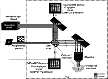
PAM is a wide-field imaging system based on structured illumination with the use of a spatial light modulator (SLM) (Verveer et al. Reference Verveer, Hanley, Verbeek, Van Vliet and Jovin1998). Figure 6 illustrates the setup of a dual path wide-field PAM. PAM uses a SLM to create a pattern of conjugated illumination and detection, which are used in real-time for the reconstruction of an optically sectioned image (Heintzmann et al. Reference Heintzmann, Hanley, Arndt-Jovin and Jovin2001). A SLM in PAM is usually an array of digital micro mirror devices (DMDs) that is used for analogue light modulation (Hanley et al. Reference Hanley, Verveer, Gemkow, Arndt-Jovin and Jovin1999). The SLM is positioned in the primary image plane of the microscope, which can be specifically programmed to incorporate structured illumination patterns in the fluorescent specimen. An arbitrary (programmable) mask can be dynamically applied as a pattern to be generated by the DMDs. The masked region defines the areas that are always ‘OFF’ and vice versa. Such a feature can be exploited for spatial control of illumination over the fluorescent specimen.
Illustrative scheme of a wide-field dual path PAM. PAM uses a SLM such as a DMD array build in the setup of a dual path PAM for spatial control of illumination patterns that can be generated and programmed dynamically during imaging. A dual path PAM records both the conjugate and non-conjugate images obtained with the DMDs in ‘ON’ and ‘OFF’ positions, respectively. Optical sectioning is also achieved by mathematical treatment of recorded conjugate and non-conjugate images. The implementation of SCIM in PAM is called MLE-PAM and can be considered as a wide-field-based, discretized version of SCIM in CLSM, where decisions for all pixels are taken at the same time in each image at constant time intervals. The illumination is then controlled by dynamically programming the patterns of a DMD array in accordance to the illumination profile required in background and foreground regions.

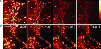
Implementation of SCIM in PAM was introduced as minimized light exposure PAM (MLE-PAM). It uses the concept of SCIM by exploiting the dynamic programmability of a DMD array (Caarls et al. Reference Caarls, Rieger, De Vries, Ardnt-Jovin and Jovin2011). Firstly, an unmasked wide-field frame is recorded using a specific exposure time ‘T d’ with all DMDs in the DMD array ‘turned ON’. Depending on the fluorescence intensities recorded in each pixel, a distinction is made between foreground and background pixels by thresholding. An illumination schedule is then constructed for each pixel. The background pixels are masked out and an illumination time is computed for the foreground pixels depending on the time estimated for each of the pixels to reach the set SNR. Then, a series of subframes are recorded each with an exposure time of ‘T d’. After recording each subframe, pixels are gradually masked out when they have exceeded their estimated illumination time in accordance with the illumination schedule. Therefore, MLE-PAM can be considered as a wide-field based discretized version of SCIM in CLSM, where decisions for all pixels are made at the same time (per image) at constant time intervals. The set of subframes are used for the reconstruction of the original image. All pixels of the illuminated regions of the subframes are summed. The summed up image is then divided by the discretized exposure time per pixel to generate the illumination profile for the reconstruction. However, the reconstructed image suffers from artefacts at the edges of the masks, because changes in illumination profile affects the measured brightness of neighbouring pixels in accordance with the objective's point spread function (PSF) (Caarls et al. Reference Caarls, Rieger, De Vries, Ardnt-Jovin and Jovin2011). These artefacts can be avoided by dilating the illumination profile with respect to the image regions, selected on the basis of the width of the PSF. Reduced photodamage when using MLE-PAM was demonstrated in tracking studies (Fig. 7), thus demonstrating the usefulness of SCIM in a wide-field microscope (Caarls et al. Reference Caarls, Rieger, De Vries, Ardnt-Jovin and Jovin2011).
Reduced photodamage in live-cell imaging of HeLa cells stained with microtracker to visualize mitochondria with MLE-PAM as reproduced from Caarls et al. (Reference Caarls, Rieger, De Vries, Ardnt-Jovin and Jovin2011). Scale bar 5 µm. (a) Conventional time-lapse imaging using wide-field PAM shows significant photodamage within 13·11 min. (b) Time-lapse imaging using SCIM and PAM (MLE-PAM) shows reduced photodamage, which allows prolonged time-lapse imaging beyond 13·11 min.

3.4 Structured illumination microscopy (SIM)
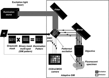
Recent advances in fluorescence optical microscopy have enabled the development of optical microscopes, that are known as nanoscopes, which generate super-resolution images with sub-diffraction resolution limits (Eggeling et al. Reference Eggeling, Willig, Sahl and Hell2015). SIM is a prominent super-resolution imaging technique that employs patterned illumination (Gustafsson, Reference Gustafsson2000; Gustafsson et al. Reference Gustafsson, Shao, Carlton, Wang, Golubovskaya, Cande, Agard and Sedat2008; Heintzmann, Reference Heintzmann2003). Spatially non-uniform illumination patterns are used for illuminating the fluorescent specimen. Interference between these illumination patterns and the specimen paves the way for the extraction of the information on high spatial-frequency components within the specimen. Various illumination patterns are used to acquire multiple images, which are then mathematically reconstructed to obtain an image with a resolution beyond the diffraction limit. From an implementation point of view, SIM can be constructed with the help of physical grids or masks which are placed in the illumination path to generate patterned illumination over the fluorescent specimen. Alternatively, SLMs such as a DMD array can be used to generate patterned illumination. SLMs also offer a higher degree of flexibility in spatio-temporal control of illumination, enabling incorporation of SCIM in a SIM as shown in Fig. 8.
Illustrative scheme of an adaptive SIM. Adaptive SIM uses a DMD array in its construction. DMD arrays are used to generate patterned (based on a binary mask), multispot illumination over one specimen. SCIM is performed with SIM by using an additional greyscale mask comprising of weighing factors by which the intensity of the illumination is scaled. Spatially controlled illumination patterns are generated by combining the two masks. Greyscale masks are updated after every single imaging sequence based on preset thresholds and illumination schemes. Series of images are obtained sequentially using different illumination patterns and are mathematically reconstructed to generate a SIM image.

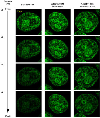
Recently, SCIM was incorporated in a SIM setup and introduced as ‘adaptive SIM’ (Chakrova et al. Reference Chakrova, Canton, Danelon, Stallinga and Rieger2016a). The principle of adaptive SIM, revolves around locally adjusting the illumination light-dose in accordance to the specimen structure. Adaptive SIM incorporates a DMD array in its construction, which is used to generate multi-spot illumination patterns. The imaging process involves sequential acquisition of raw images with multi-spot illumination patterns. Initially, a wide-field image is obtained by employing a very low illumination light dose. Based on the information obtained from this image, a greyscale mask is computed. The greyscale mask contains the weighing factors, with which the intensity of the illumination is scaled for the next step in the imaging sequence. Weighing factors are determined on the basis of the intensities in the image. A minimum weighing factor ‘w min’ is used for background regions, which have intensities lower than a preset threshold intensity ‘I min’ or for strong foreground regions, which have intensities higher than a preset threshold intensity ‘I max’. For the weak foreground regions of which the intensity is between ‘I min’ and ‘I max’, the weighing factors are computed as either a linear or non-linear function, by increasing the weights of lower intensities or vice versa. The greyscale mask with the weighing functions is used in conjunction with the binary multi-spot illumination pattern for scaling the illumination intensity for the next sequence of imaging. Finally, the obtained raw images are mathematically reconstructed using the ‘pattern-illuminated Fourier ptychography’ algorithm (Chakrova et al. Reference Chakrova, Heintzmann, Rieger and Stallinga2015, Reference Chakrova, Rieger and Stallinga2016b). By spatially-controlling the illumination light dose in a SIM setup, lower photodamage was observed during time-lapse imaging of human embryonic kidney 293T (HEK 293T) cells with SYTOX-stained DNA as shown in Fig. 9. In comparison with the imaging time (before complete photobleaching) on a standard SIM setup, adaptive SIM was able to achieve prolonged imaging times by a factor 3 without significant reduction in image quality (Chakrova et al. Reference Chakrova, Rieger and Stallinga2016a).
Reduced photodamage in live-cell imaging of HEK 293T cells, in which DNA is labelled with SYTOX using adaptive SIM as reproduced from Chakrova et al. (Reference Chakrova, Rieger and Stallinga2016a). Comparison of photobleaching effects over imaging time using standard SIM and adaptive SIM with linear and non-linear masks is shown. Scale bar, 2 µm. (a) First acquired image. (b) Image acquired after 10 min from the 20th acquisition. (c) Image acquired after 20 min from the 40th acquisition. (d) Image acquired after 30 min from the 60th acquisition. Upon 30 min of imaging time, the specimen is subjected to heavy photobleaching effects when imaged using a standard SIM setup. In comparison, photobleaching effects are significantly lower when imaged using adaptive SIM, which incorporates the principle of SCIM in its operation.

3.5 Stimulated-emission depletion microscopy (STED)
STED is a super-resolution technique, whose principle is based on the distinction of 2 different states of a fluorescent probe, their ‘ON’ and ‘OFF’ states (Eggeling et al. Reference Eggeling, Willig, Sahl and Hell2015; Hell & Wichmann, Reference Hell and Wichmann1994). STED achieves this by employing 2 illumination beams, one to turn ‘ON’ the fluorescent probes (the excitation beam) and the other to turn ‘OFF’ fluorescent probes (the depletion beam) (Hell & Wichmann, Reference Hell and Wichmann1994). Superresolution images are obtained by generating a doughnut-shaped excitation pattern with the depletion beam surrounding the excitation beam, while the volume of the excitation beam is limited to sub-diffraction dimensions. Pointwise scanning of the beam over the targeted region can generate super-resolution images.
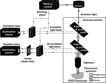
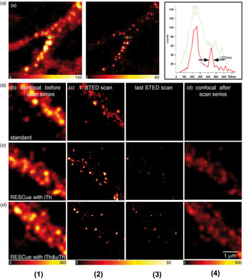
A major limiting factor of live-cell imaging using STED nanoscopy is photodamage or photo-stress induced by the depletion and excitation beams in the fluorescent specimen. Strong illumination (high laser power) is needed to obtain high resolution. Moreover, when smaller pixels/step sizes (or more scanning steps) are applied for better resolution or when 3D imaging is performed, the fluorescent probes undergo frequent transitions from the ‘ON’ state to the ‘OFF’ state and vice versa with a high risk of photodamage (Eggeling et al. Reference Eggeling, Willig, Sahl and Hell2015). Therefore, STED nanoscopy has been combined with SCIM that was introduced as ‘RESCue STED’ (reduction of excitation and signal suppression cycles) nanoscopy (Staudt et al. Reference Staudt, Engler, Rittweger, Harke, Engelhardt and Hell2011). The approach is to minimize the ON–OFF transitions of fluorescent probes by applying an intelligent exposure scheme based on SCIM. The foreground strategy is employed to ‘turn OFF’ illumination of both the excitation and depletion beams, when the detected number of photons reaches a specific threshold that was selected on the basis of a desired SNR. It prevents unnecessary excitations or switching of fluorescent probes, resulting in reduced photodamage. Similarly, the background strategy is employed by comparing the amount of photons detected from a sub-diffraction region (or volume to which the excitation beam is confined) with a set background threshold at a set background decision time. When the number of detected photons is below the background threshold, the region is treated as background and both illumination beams are ‘turned OFF’ for the residual pixel dwell time. This is performed by issuing a blanking signal to the acousto-optic tunable filter (AOTF), which acts as a shutter. The AOTF shuts off illumination, thereby preventing unnecessary transitions of fluorescent probes, especially in the out-of-focus regions. This setup was implemented by using a real-time closed-loop feedback control between the detection and illumination units as shown in Fig. 10. The combination of powerful techniques such as STED and SCIM enables four to eight times prolonged live-cell imaging of biological specimens at super-resolution. A 4-fold reduction in photodamage was demonstrated with the imaging of fluorescently-labelled proteins in fixed primary mouse neurons (Fig. 11) (Staudt et al. Reference Staudt, Engler, Rittweger, Harke, Engelhardt and Hell2011).
Illustrative scheme of RESCue STED microscopy. STED employs two illumination sources, which are combined to generate a doughnut-shaped illumination profile, which is used to ‘turn ON’ the fluorescent probes at the center with the excitation beam and ‘turn OFF’ all the adjacent fluorescent probes with the depletion beam to achieve super-resolution. SCIM in STED (RESCue STED) is implemented using a real-time feedback unit controlling the AOTF shutter which is used to ‘turn ON’ and ‘turn OFF’ the illumination beams when required.

Imaging of fluorescently labelled proteins in fixed primary mouse neurons using STED nanoscopy and reduced numbers of excitation and signal suppression cycles (RESCue) STED as reproduced from Staudt et al. (Reference Staudt, Engler, Rittweger, Harke, Engelhardt and Hell2011). Scale bar, 1 µm. (a) Conventional imaging with spatially-uniform illumination using CLSM and STED nanoscopy with a 50 nm spatial resolution. (b) Conventional imaging with uniform illumination results in photodamage. (c) Imaging with foreground illumination strategy of SCIM using a fixed threshold of ‘ITh’, reduces photodamage. (d) Imaging with both the foreground and background strategy of SCIM using background threshold ‘uTh’ and foreground threshold ‘ITh’, provides more photodamage reduction. *(1) & (2) shows the images of a fluorescent sample captured with a confocal and a STED microscope respectively, before scanning. (3) & (4) shows the images after scanning, using confocal and STED microscopes, respectively.

4. Outlook
4.1 Relevance of SCIM
Live-cell and live-tissue imaging with fluorescence microscopy is useful to observe components within a living specimen with a high degree of specificity, but is limited by photodamage. Several considerations such as the nature of the study, the required image resolution, the imaging speed, the duration of imaging and the risk of photodamage have to be taken into account when selecting a specific type of fluorescence optical microscope. However, irrespective of the selection of a fluorescence optical microscope one pertinent question still stands out, namely the determination of optimal illumination light dose that is required for imaging. The issue can be further complicated by the fact that spatially, specific regions of the fluorescent specimen may require more illumination than others due to their differences in the amount of fluorescence signal. Estimation of the exact levels of optimal light dose prior to the start of experiment can be a complex task. Real-time estimation during imaging certainly provides a more accurate solution to this problem. SCIM offers an attractive solution with real-time estimation and spatial control of illumination.
An additional benefit of SCIM is the inherent HDR imaging feature. Researchers often encounter situations where there are both weakly and strongly fluorescent regions within one specimen while performing fixed cell or live-cell imaging. Detection of these signals with a large difference in the magnitude of a fluorescence signal usually requires a sensitive detector (or camera) with a large dynamic range. However, the dynamic range is fundamentally limited by the physical capabilities of the detector. Non-linear rescaling of images recorded by the use of sensitive single-photon detectors can be used to obtain HDR. Alternatively, multiple images can be captured with different illumination levels to mathematically combine them in a meaningful manner to obtain HDR images (Bell et al. Reference Bell, Brauers, Kaftan, Meyer-Ebrecht, Böcking and Aach2009). HDR imaging usually requires repeated exposure of the fluorescent specimen to illumination which can potentially cause photodamage. Moreover, HDR imaging using multiple exposures becomes problematic when it comes to imaging of non-stationary specimens, as is often the case in live-cell imaging. In comparison, SCIM has an inherent HDR feature with its spatial control of illumination. HDR images are obtained during a single exposure by precisely controlling the illumination. It allows for the use of low-dynamic-range ultra-sensitive detectors. With uniform detections, the data rate from the detector (or camera) can be significantly reduced, leading to faster operations and data compression.
The relevance of SCIM is evident because of reduced photodamage, extended dynamic range and data compression. Each of these factors are prominent issues in the world of microscopy. For example, the majority of the super-resolution techniques use a strong illumination light dose to achieve high resolution which makes live-cell and live-tissue imaging difficult due to photodamage and SCIM can reduce that. Another example is the imaging of neurons with dendrites where the extended dynamic range is required to image the weakly fluorescent dendrites along with the strongly fluorescent body of the cell.
SCIM has been successfully implemented in confocal, two-photon microscopes, PAM, SIM and STED (Fig. 12). However, the implementation of SCIM is not limited to these types of microscopes, it can find its way to other fluorescence microscope techniques such as light-sheet microscopy and localization microscopy.
Prominent fluorescence-based optical microscopes that are available for live-cell and/or live-tissue imaging. SCIM has been implemented in both confocal and wide-field systems with optical sectioning capabilities.

4.2 SCIM in light-sheet microscopy
Light-sheet microscopy or selective plane illumination microscopy (SPIM) is an efficient microscopic technique for imaging living biological specimens or multicellular organisms. It uses a thin sheet of light for illumination providing optical sectioning (Huisken et al. Reference Huisken, Swoger, Del Bene, Wittbrodt and Stelzer2004; Stelzer, Reference Stelzer2015). Consequently, it avoids unnecessary excitation of fluorescent probes in the out-of-focus regions and thus reduces photodamage (Huisken et al. Reference Huisken, Swoger, Del Bene, Wittbrodt and Stelzer2004; Stelzer, Reference Stelzer2015). The spatial intensity profile of the light sheet dictates the spatial resolution, optical sectioning capability, field of view and the extent of photodamage for a given numerical aperture of the detection system (Fu et al. Reference Fu, Martin, Matus and Gao2016). However, a single ‘perfect light-sheet’ does not exist, which allows for an optimum spatial resolution, optical sectioning capability and range of the field of view. A trade-off between the resolution and range of the field of view is a fundamental limitation in light-sheet microscopy (Fu et al. Reference Fu, Martin, Matus and Gao2016). Different spatial profiles of light sheets are used to achieve different ends of the trade-off. For instance, in tiling light-sheet SPIM (TLS-SPIM), thinner light sheets covering a part of the field of view are generated and placed over several positions of the sample (tiling) to achieve an optimum spatial resolution and field of view by sacrificing imaging speed (Gao, Reference Gao2015). The light sheet may be placed over several regions of the sample by either adjusting the objective, moving the sample specimen or by employing SLMs. The digital scanned laser light-sheet fluorescence microscopy and lattice light-sheet microscopy employ a digital laser scanner for this purpose (Chen et al. Reference Chen, Legant, Wang, Shao, Milkie, Davidson, Janetopoulos, Wu, Hammer, Liu, English, Mimori-Kiyosue, Romero, Ritter, Lippincott-Schwartz, Fritz-Laylin, Mullins, Mitchell, Bebenek, Reymann, Böhme, Grill, Wang, Seydous, Tulu, Kiehart and Betzig2014; Keller et al. Reference Keller, Schmidt, Wittbrodt and Stelzer2008). Other approaches of spatial modulation of a light sheet include the use of Bessel beams and Airy beams to achieve higher spatial resolution (Fahrbach & Rohrbach, Reference Fahrbach and Rohrbach2012; Fahrbach et al. Reference Fahrbach, Simon and Rohrbach2010; Planchon et al. Reference Planchon, Gao, Milkie, Davidson, Galbraith, Galbraith and Betzig2011; Vettenburg et al. Reference Vettenburg, Dalgarno, Nylk, Coll-Lladó, Ferrier, Čižmár, Gunn-Moore and Dholakia2014). Although those approaches can provide a higher spatial resolution, it still employs a light beam with focused high energy over the sample (Daetwyler & Huisken, Reference Daetwyler and Huisken2016). Employing these light-sheet patterns may still lead to photodamage during prolonged imaging.
In comparison with the concept of SCIM, light-sheet microscopy has an inherent background strategy in its operations by specifically employing illumination of a selected plane in focus. From an implementation point of view, SCIM uses real-time decisions to distinguish background and foreground regions to control illumination, whereas light-sheet microscopy adopts a more direct optical approach by avoiding illumination of out-of-focus regions. SCIM is susceptible to errors during real-time estimation due to the stochasticity of the detected signal whereas the thickness of the light sheet may become a limiting factor in light-sheet microscopy (Hoebe et al. Reference Hoebe, Van Noorden and Manders2010; Stelzer, Reference Stelzer2015). The background strategy largely revolves around spatial selection of background regions to turn OFF the illumination. Therefore, light-sheet microscopy, just like two-photon microscopy, has a ‘spatially-selective’ illumination strategy. The concept of SCIM also revolves around the foreground strategy which has a ‘spatially-controlled’ illumination light dose, by turning ON the illumination in the foreground regions sufficiently. Recently, real-time feedback-based controlled illumination was implemented in TLS-SPIM by switching between the Gaussian, Bessel and Lattice light-sheet profiles during imaging (Fu et al. Reference Fu, Martin, Matus and Gao2016). Spatial control of illumination in light-sheet microscopy can be implemented on the basis of real-time feedback of the spatial profile of the sample in X–Y (tiled approach) or Z (plane wise) or even tomography in case the sample is moved or rotated when imaging large specimens using a scanning-based approach.
5. Conclusions
Targeted controlled illumination with SCIM enhances the prospects of live-cell and live-tissue imaging by striking a good balance between photodamage and image quality. In its implementation, SCIM is an ‘add-on’ based solution, which has found its applications in various types of fluorescence microscopes used for live-cell imaging. SCIM uses an alternative imaging strategy by spatially varying illumination, and striving for a constant detection in background and foreground regions which yields a HDR. Moreover, photodamage is reduced without compromising image quality, which is a huge plus for prolonged live-cell and live-tissue imaging. The risk of photodamage depends on a number of factors related to the microenvironment of the biological specimen, including the temperature, the type of fluorescent probes used and chemical composition of the biological specimen. Control over all aspects of the microenvironment of biological specimens is generally limited, especially in live-cell imaging. However, exact control of the illumination light dose which is primarily responsible for the occurrence of photodamage is possible. Therefore, the application of ‘spatial selection’ and ‘spatial control’ of illumination in SCIM is a helpful tool, especially because it offers a universal solution towards minimization of photodamage irrespective of the microenvironmental conditions of the fluorescent specimen.
Acknowledgements
We like to thank Jan Stap for the useful discussions. We also thank our funding partners, Nikon Microscopy and Dutch Technology Foundation STW (project number 11350), which is a part of the Netherlands Organization for Scientific Research (NWO).
Author contribution
All authors contributed equally to the manuscript.
Conflict of interest
The authors declare that they have no competing financial interests.