Nomenclature
- L, D
-
lift and drag accelerations
- CL, CD
-
lift and drag coefficients
- g0
-
gravitational acceleration
- Sref
-
reference area
-
 $\rho$
-
air density
- Q
-
heating rate,
- q
-
dynamic press
- ny
-
aerodynamic load
- R0
-
radius of the earth
- s
-
reentry range
- e
-
energy of the reentry vehicle
-
$\psi_{LOS}$
-
line of sight
- kq
-
heat transfer coefficient
- we
-
rotational angular velocity of the earth
-
$\sigma$
-
bank angle
-
$\alpha$
-
angle of attack


1.0 Introduction
The hypersonic glide vehicle has an advantage of high speed, long range, high precision, strong manoeuverability and penetration capability as a weapon which receives extensive attention in various countries in recent years [Reference Zhao, Zhou and Jin1,Reference Sarah and Nesrin2]. Reentry guidance of hypersonic vehicles refer to generate an online command to direct the hypersonic vehicles to fly to a designated terminal location, while meeting the path constraints such as heating rate and dynamic load [Reference Shen and Lu3].
The reentry guidance method is divided into two categories: standard trajectory guidance and predictor corrector guidance. Standard trajectory guidance requires offline designing of the standard trajectory for the vehicle and obtaining guidance commands through online tracking of the standard trajectory [Reference Zhao4]. The method is simple to implement and has a small amount of online calculation, but depends on the standard trajectory, which is sensitive to disturbance, and is not conducive to online planning of the trajectory. The predictor corrector guidance doesn’t depend on the standard trajectory. The guidance command is corrected in real time according to the deviation between the predictive value and the expected value. The predictor corrector guidance has strong robustness to the initial error and parameter perturbation, and the real-time performance is good. With the improvement of autonomy and robustness requirements of reentry tasks, predictor corrector guidance has gradually become the trend of reentry guidance development [Reference Lu5].
In literature [Reference Spratlin6], the linear relationship between the angle-of-attack, the bank angle, the longitudinal range and the lateral range were established by numerical prediction, and the control variable was corrected according to the control objective. The literatures [Reference Xue and Lu7–Reference Wang, Li and Ren9] transformed the path constraints into the amplitude of bank angle constraints, and then used the bank angle profile to predict the terminal flight range and correct the bank angle command. In literature [Reference Shui, Zhou and Ge10], a segmentation predictor corrector guidance algorithms was designed. The trajectory segmentation predictor was performed by using preset route points, which improved the computational efficiency. However, the method relied on offline optimisation and reduced the autonomy of the algorithm. In literatures [Reference Lu, Brunnerc and Stachowiak11,Reference Fu, Liu and Chen12], numerical predictor corrector guidance algorithms for various types of lift-to-drag ratio vehicles were designed and improved. The bank angle profile was updated through the cross-range error, and supplemented by the altitude change rate feedback to meet the path constraints. All of the above methods belong to the numerical predictor corrector guidance, which requires continuous online numerical integration and has higher requirements for the calculation capacity of the vehicle computer.
Another method is analytical predictor guidance, which avoids the numerical integration of the trajectory, and the amount of calculation is greatly reduced. However, the analytical method for obtaining the bank angle is generally based on the quasi-equilibrium glide condition (QEGC) in reentry process, but the vehicle may not satisfy the QEGC, so the accuracy of the method cannot be guaranteed. Literature [Reference Hu, Guo and Cai13] studied the analytical predictor guidance of kinetic energy warheads under zero angle-of-attack conditions, but it wasn’t suitable for hypersonic glide vehicle. In literature [Reference Kluever14], the analytical predictor corrector guidance for skip reentry was studied, which was only applicable to low lift-to-drag ratio vehicle. In literature [Reference Hu, Zhang and Chen15], the lift coefficient was divided into three components, which realised the decoupling of the longitudinal motion equation, the lateral motion equation and the velocity equation, and obtained the analytical solution of the gliding trajectory, but still needed numerical integration. In literature [Reference Li, Zhang and Li16], the path constraints were transformed into an analytical expression in the height-velocity plane, and the closed-loop analytical solution of the reusable vehicle was given, but the method was a standard trajectory generation method essentially. In literature [Reference Zeng, Wang and Wang17], the analytical relationship between the bank angle and the range-to-go was obtained with the constant lift-to-drag ratio, but the QEGC could not be guaranteed, and the terminal height wasn’t strictly restricted.
Besides entry trajectory planning methods, there are a great number of innovative methods based either on onboard optimisation or onboard interpolation. These methods also can generate real-time-capable entry guidance solutions. In Ref. [Reference Schierman and Hull18], a new real-time trajectory command generation approach for RLVs was developed. By describing decision variables in terms of appropriate basis functions, the trajectory optimisation problem was reformulated to find the relatively few basis function coefficients that characterise the desired trajectory. In Ref. [Reference Bollino, Ross and Doman19], a pseudospectral guidance algorithm was investigated to solve the onboard, real-time, optimal trajectory generation for RLVs and was capable of compensating for large uncertainties. In Refs [Reference Wang and Grant20–Reference Sagliano, Mooij and Theil23], the online constrained entry trajectory optimisation problems were solved by several convex optimisation methods. In Ref. [Reference Sagliano, Mooij and Theil24], the multivariate pseudospectral interpolation approach was coupled with an algorithm of subspace selection to be able to generate online nearly optimal real-time trajectories for entry scenarios in the presence of wide dispersions at the entry interface.
In the existing researches, the terminal constraints usually include the terminal range-to-go, altitude and velocity. In addition, for long-range manoeuvering entry vehicles, no-fly zones is a type of geographic constraint that shall be satisfied in entry trajectory planning. The no-fly zones may be some important zones such as large cities that the entry flight should keep away from for security, and some other special zones will have to be avoided for threat avoidance or due to geopolitical restrictions. The vehicle must avoid specified no-fly zones for threat avoidance. In Refs [Reference Jorris and Cobb25] and [Reference Jorris and Cobb26], 2-D and 3-D trajectory optimisation methods satisfying no-fly zone constraints were designed for entry vehicles. In Ref. [Reference Zhao and Zhou27], the Gauss pseudospectral method was used to generate the optimal trajectory satisfying geographic constraints. However, the optimisation methods are time-consuming and not suitable for online use. Some real-time capable planning methods have been developed [Reference Guo, Wu and Tang28–Reference Liang, Liu and Li34]. In Ref. [Reference Zhang, Liu and Wang30], the relationship between the attraction and repulsion force was described, and it was possible to use artificial potential field methods to avoid no-fly zones. In Refs [Reference He, Liu and Tang31] and [Reference Xie, Liu and Liu32], no-fly zone constraints were transformed into a series of virtual waypoints by geometric planning algorithm. These two methods mainly originate from unmanned air vehicles and mobile robots trajectory planning and may not be suitable for entry vehicles due to their low manoeuverability. In Refs [Reference Guo, Wu and Tang28] and [Reference Xie, Liu and Tang33], the bank angle reversal logics were designed based on dynamic heading angle corridors to determine the sign of the bank angle.
For the terminal constraints, the constraint of terminal range-to-go doesn’t strictly constrain the terminal altitude, that is to say, there exists mismatch between the cross range and the altitude. For the case when the terminal range and the terminal altitude are mismatched, the traditional method can only guarantee the range constraint, and the altitude error is large. Based on this, this paper proposes a predictor corrector guidance method based on the bank angle profile and can strictly satisfy the terminal altitude and the no-fly zone constraints. Firstly, the relationship between the bank angle profile and the terminal range and altitude is analysed, and the possible mismatch between the terminal range and altitude are pointed out. Then, a segment linear bank angle profile is designed. By selecting the initial and terminal bank angle reasonably, the altitude and velocity constraints are satisfied, and the cross-range error is corrected by the predictor of range-to-go to ensure the range constraint. And the bank angle reversal logic ensures the no-fly zone constraint and lateral guidance accuracy. The simulation results show that the algorithm can constrain the terminal range, altitude and velocity and at the same time and meet the no-fly zone constraint and has good adaptability.
The remainder of this paper is organised as follows. In Section 2, the entry trajectory planning problem is described. Section 3 presents the whole planning algorithm. The simulation results using the CAV-H model are shown in Section 4, and the work is summarised in Section 5.
2.0 Problem statement
2.1 Equations of motion
In this paper, the earth is considered as a rotating spherical model. Then the three degree of freedom point mass equations of motion of an entry vehicle are as follows:
 \begin{align}\left\{ \begin{array}{l}\dfrac{{\textrm{d}r}}{{\textrm{d}t}} = V\sin \theta \\[8pt]\dfrac{{\textrm{d}\lambda }}{{\textrm{d}t}} = \dfrac{{V\cos \theta \sin {\psi _V}}}{{r\cos \phi }}\\[8pt]\dfrac{{\textrm{d}\phi }}{{\textrm{d}t}} = \dfrac{{V\cos \theta \cos {\psi _V}}}{r}\\[8pt]\dfrac{{\textrm{d}V}}{{\textrm{d}t}} = - D - \dfrac{{\sin \theta }}{{{r^2}}} + \omega _e^2r\cos \phi (\!\sin \theta \cos \phi - \cos \theta \cos {\psi _V}\sin \phi )\\[8pt]\dfrac{{\textrm{d}\theta }}{{\textrm{d}t}} = \dfrac{1}{V}\left[L\cos \sigma + \left({V^2} - \dfrac{1}{r}\right)\dfrac{{\cos \theta }}{r} + 2{\omega _e}V\cos \phi \sin {\psi _V} + \right.\\[8pt] \left. \qquad\;\; \omega _e^2r\cos \phi (\cos \theta \cos \phi + \sin \theta \sin \phi \cos {\psi _V})\right]\\[8pt]\dfrac{{d{\psi _V}}}{{dt}} = \dfrac{1}{V}\left[\dfrac{{L\sin \sigma }}{{\cos \theta }} + \dfrac{{{V^2}}}{r}\cos \theta \sin {\psi _V}\tan \phi\; + \right. \\[8pt] \left. \qquad\quad 2{\omega _e}V(\cos \phi \cos {\psi _V}\tan \theta - \sin \phi ) + \dfrac{{\omega _e^2r\sin {\psi _V}\sin \phi \cos \phi }}{{\cos \theta }}\right],\end{array} \right.{}\end{align}
where
 $r$
is the radius from the earth center to the vehicle,
 $\lambda $
and
 $\phi $
are the longitude and latitude, respectively,
 $V$
is the velocity of the vehicle,
 $\theta $
is the flight-path angle,
 ${\psi _V}$
is the heading angle measured from the north in clockwise direction,
 ${\omega _e}$
is the rotational angular velocity of the earth,
 $\sigma $
is the bank angle,
 $L$
and
 $D$
are the lift and drag accelerations, respectively. All variables are dimensionless.
 $L$
and
 $D$
can be calculated by:
 \begin{align}\left\{ \begin{array}{l}L = \dfrac{1}{{2m{g_0}}}\rho {\left( {{V_c}V} \right)^2}{C_L}\left( {\alpha ,{V_c}V} \right){S_{ref}}\\[10pt]D = \dfrac{1}{{2m{g_0}}}\rho {\left( {{V_c}V} \right)^2}{C_D}\left( {\alpha ,{V_c}V} \right){S_{ref}}\end{array}, \right.{}\end{align}
where
 $m$
is the mass of the vehicle,
 ${g_0}$
is the gravitational acceleration of sea level,
 ${V_c} = \sqrt {{g_0}R} $
is the dimensionless parameter of flight speed,
 ${C_L}$
and
 ${C_D}$
are the lift and drag coefficients, respectively,
 $\alpha $
is the angle-of-attack,
 ${S_{ref}}$
is the reference area of the vehicle,
 $\rho $
is the air density which is calculated by:
 \begin{align}\rho \left( H \right) = {\rho _0}{e^{ - \beta \cdot H}}{,}\end{align}
where
 $H$
is the altitude,
 ${\rho _0} = 1.225\,{\rm{kg/}}{{\rm{m}}^{\rm{3}}}$
is the air density at sea level and
 $\beta = 1/7110$
.
2.2 Trajectory constraints
Typical reentry process constraints include:
-
(1) Path constraints:
 \begin{align}\dot Q = {C_Q}{\rho ^{0.5}}{\left( {{V_c}V} \right)^{3.15}} \le {\dot Q_{\max }}{,}\end{align}
 \begin{align}q = \frac{1}{2}\rho {\left( {{V_c}V} \right)^2} \le {q_{\max }}{,}\end{align}
 \begin{align}{n_y} = \sqrt {{L^2} + {D^2}} \le {n_{\max}}{,}\end{align}
where
 $\dot Q$
,
 $q$
,
 ${n_y}$
are the stagnation point heating rate, dynamic pressure and total aerodynamic load, respectively. And
 ${\dot Q_{\max }}$
,
 ${q_{\max }}$
,
 ${n_{\max }}$
are the maximum limits of them, respectively.
 ${k_Q} = 0.00015$
is a heat transfer coefficient. These three constraints are rigid constraints and must be satisfied.
In the lifting entry trajectory, the flight-path angle
 $\theta $
is small and varies slowly. Setting
 $\cos \theta = 1$
and
 $\dot \theta = 0$
in the dynamics equations of flight-path angle and ignoring the earth rotation gives:
 \begin{align}L\cos \sigma + \left( {{V^2} - \frac{1}{r}} \right)\frac{1}{r} = 0.\end{align}
Since
 $\cos \sigma \le 1$
must be satisfied, we obtain:
 \begin{align}L + \left( {{V^2} - \frac{1}{r}} \right)\frac{1}{r} \ge 0,\end{align}
which is called the quasi-equilibrium glide condition (QEGC) [Reference Shen and Lu3]. It means that only when the H–V profile is located below this QEGC boundary, the flight-path angle can be controlled by adjusting the bank angle.
-
(2) Terminal constraints:
In this paper, the terminal constraints are given as follows.
 \begin{align}\begin{array}{l}\left| {{r_f} - r_f^ * } \right| \le {\varepsilon _r}, \left| {{\lambda _f} - \lambda _f^ * } \right| \le {\varepsilon _\lambda } \\[4pt] \left| {{\phi _f} - \phi _f^ * } \right| \le {\varepsilon _\phi }, \left| {{V_f} - V_f^ * } \right| \le {\varepsilon _V},\end{array}\end{align}
where
 $\left( {{r_f},{\lambda _f},{\phi _f},{V_f}} \right)$
are the terminal states of the vehicle,
 $\left( {r_f^ * ,\lambda _f^ * ,\phi _f^ * ,V_f^ * } \right)$
are the desired terminal states,
 $\left( {{\varepsilon _r},{\varepsilon _\lambda },{\varepsilon _\phi },{\varepsilon _V}} \right)$
are the corresponding permissible errors.
-
(3) Geographic constraints:
No-fly zones and waypoints are two kinds of geographic constraint that shall be satisfied in entry trajectory planning. The vehicle must avoid the no-fly zones and cross from the waypoints. The waypoint constraint can be expressed as a point
 $\left( {{\lambda _w},{\phi _w}} \right)$
that should be passed. The terminal constraints can also be regarded as waypoint constraints. The no-fly zone model is an infinitely high cylinder, whose center is
 $\left( {{\lambda _n},{\phi _n}} \right)$
with a radius of
 ${R_n}$
. The no-fly zone constraint can be expressed as that all the points
 $\left( {{\lambda _M},{\phi _M}} \right)$
in the entry trajectory satisfying:
 \begin{align}{S_n}\left( {{\lambda _M},{\phi _M},{\lambda _n},{\phi _n}} \right) \gt {R_n},\end{align}
where
 ${S_n}\left( {{\lambda _M},{\phi _M},{\lambda _n},{\phi _n}} \right) = {R_0}\arccos \left( {\sin {\phi _M}\sin {\phi _n} + \cos {\phi _M}\cos {\phi _n}\cos \left( {{\lambda _M} - {\lambda _n}} \right)} \right)$
.
 ${R_0}$
is the radius of the earth.
-
(4) Control constraints:
The control variables in entry trajectory planning are usually the angle-of-attack
 $\alpha $
and bank angle
 $\sigma $
. And they are constrained within a specific range due to the practical flight conditions:
 \begin{align}{\alpha _{\min }} \le \alpha \le {\alpha _{\max }}, {\sigma _{\min }} \le \sigma \le {\sigma _{\max }},\end{align}
where
 ${\alpha _{\min }}$
,
 ${\alpha _{\max }}$
are the minimum and maximum constrained values of
 $\alpha $
, respectively, and
 $ {\sigma _{\min }}$
,
 ${\sigma _{\max }}$
are the minimum and maximum constrained values of
 $\sigma $
, respectively.
3.0 Planning algorithm
3.1 Constraint conversion and reentry corridor
This paper employs altitude-versus-velocity (H-V) plane to design the entry corridor and determine the maximum and minimum boundaries allowed. Since the boundaries of the constraints such as overload and QEGC are obtained under a certain angle-of-attack, it is necessary to design a nominal angle-of-attack in advance according to the capability of the vehicle. In this paper, the nominal angle-of-attack is defined as a function of velocity:
 \begin{align}\alpha = \left\{ \begin{array}{l@{\quad}l}{\alpha _{\max }}& V \gt {V_1}\\[4pt]\dfrac{{{\alpha _{L/{D_{\max }}}} - {\alpha _{\max }}}}{{{V_2} - {V_1}}}\left( {V - {V_1}} \right) + {\alpha _{\max }} & {V_2} \le V \le {V_1}\\[4pt]{\alpha _{L/{D_{\max }}}} & V \lt {V_2},\end{array} \right.{}\end{align}
where
 ${\alpha _{\max }}$
the maximum angle-of-attack,
 ${\alpha _{L/{D_{\max }}}}$
is the angle-of-attack which has the largest lift-to-drag ratio,
 ${V_1}$
and
 ${V_2}$
are two specific velocities. The purpose of designing the angle-of-attack function in (12) is to decelerate rapidly in the early stage of reentry, and increase the altitude of the first heat rate peaking point as much as possible to meet the heating rate constraints. When the vehicle crosses the peaking point of the first heat rate, it then flies with the maximum lift-to-drag ratio, which increase the cross range in the gliding phase. The schematic diagram of the nominal angle-of-attack is shown in the Fig. 1.
Nominal angle-of-attack.

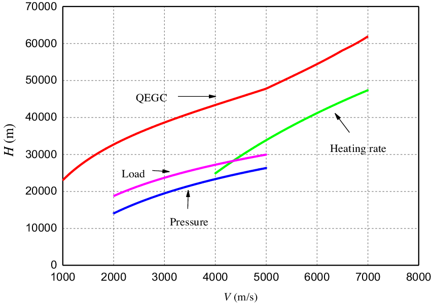
Then the path constraints (4)–(7) can be transformed into an entry corridor in H-V plane. The upper boundary of the entry corridor is defined by QEGC and the lower boundary is defined by heating rate, dynamic pressure and aerodynamic load constraints. The entry corridor based on H-V plane is described as follows:
 \begin{align}\left\{ \begin{array}{l}{H_{\min }}(V) = \max \left( {{H_{{{\dot Q}_{\max }}}}(V),{H_{{q_{\max }}}}(V),{H_{{n_{{y_{\max }}}}}}(V)} \right)\\[4pt]{H_{\max }}(V) = {H_{QEGC}}(V),\end{array} \right.{}\end{align}
where
 ${H_{\min }}(V)$
,
 ${H_{\max }}(V)$
are the upper boundary and lower boundary of the entry corridor, respectively,
 ${H_{{q_{\max }}}}(V)$
,
 ${H_{{n_y}_{\max }}}(V)$
,
 ${H_{{{\dot Q}_{\max }}}}(V)$
,
 ${H_{QEGC}}(V)$
represent the altitude constraints of the dynamic pressure, aerodynamic load, heating rate and QEGC under a certain velocity, respectively. From (2)–(6), (13), a mathematical expression of the basic reentry corridor boundary can be determined, as follows:
 \begin{align}\begin{array}{l}H \gt \dfrac{2}{\beta }\ln \left( {\dfrac{{{C_Q}{V^{3.15}}}}{{{{\dot Q}_{s\max }}}}} \right) = {H_{{{\dot Q}_{max}}}}(V)\\[10pt]H \gt \dfrac{1}{\beta }\ln \left( {\dfrac{{{\rho _0}{V^2}}}{{2{q_{\max }}}}} \right) = {H_{{q_{max}}}}(V)\\[10pt]H \gt \dfrac{1}{\beta }\ln \left( {\dfrac{{{\rho _0}{V^2}S\sqrt {C_D^2 + C_L^2} }}{{2{n_{y\max }}m{g_0}}}} \right) = {H_{{n_{y\max }}}}(V).\end{array}{}\end{align}
QEGC in (7) has no analytical solution and needs to be solved by numerical method. In this paper, a dichotomy method is used for any given velocity, and a sufficiently accurate
 ${H_{QEGC}}$
is obtained by iterating 10 times in the range of 25–80 km. QEGC is a soft constraint and the reentry corridor obtained by the above constraints is shown in Fig. 2.
Reentry corridor.

In order to convert the QEGC into the bank angle boundary, the constraint conditions (4)–(6) of the reentry corridor are brought into Equation (7), and the bank angle function is obtained with velocity as the independent variable.
 \begin{align}\begin{array}{l}{\left| \sigma \right|_{QEG\_\dot Q}}(V) = {\left| \sigma \right|_{QEG\_\dot Q}}\left( {{H_{{{\dot Q}_{max}}}}(V),V} \right)\\[4pt]{\left| \sigma \right|_{QEG\_q}}(V) = {\left| \sigma \right|_{QEGQ\_q}}\left( {{H_{{q_{max}}}}(V),V} \right)\\[4pt]{\left| \sigma \right|_{QEG\_n}}(V) = {\left| \sigma \right|_{QEGQ\_n}}\left( {{H_{{n_{y\max }}}}(V),V} \right){.}\end{array}\end{align}
Then the upper boundary of the bank angle in the gliding phase is:
 \begin{align}{\left| \sigma \right|_{\max }}(V) = \min \left( \begin{array}{l}{\left| \sigma \right|_{QEG\_\dot Q}}\left( {{H_{{{\dot Q}_{max}}}}(V),V} \right)\\[4pt]{\left| \sigma \right|_{QEGQ\_q}}\left( {{H_{{q_{max}}}}(V),V} \right)\\[4pt]{\left| \sigma \right|_{QEGQ\_n}}\left( {{H_{{n_{y\max }}}}(V),V} \right).\end{array} \right){}\end{align}
Let
 ${\sigma _{QEGC}} = 0$
be the lower boundary of the bank angle in the gliding phase, therefore, for any velocity
 $V$
in the gliding phase, as long as it satisfies
 \begin{align}{\sigma _{QEGC}} \le \sigma(V) \le {\sigma _{\max }}(V).\end{align}
Equation (17) can guarantee the vehicle’s flight trajectory will always remain within the reentry corridor. From (17), the bank angle is restricted during the reentry process, and the bank angle corridor is shown in Fig. 3.
Bank angle corridor.

3.2 Bank angle profile analysis
The core of the predictor corrector algorithm is to design the bank angle profile while latitude and longitude constraints are usually transformed into range constraints in designing longitudinal trajectory, Thus it is necessary to analyse the relationship between the bank angle profile with the reentry range, altitude, velocity. For reentry range
 $s$
there is:
 \begin{align}\dot s = \frac{{V\cos \theta }}{r}.\end{align}
From (18) and the fourth equation in (1), the derivative of range to velocity can be obtained:
 \begin{align}\frac{{ds}}{{dV}} = - \frac{{Vr\cos \theta }}{{\sin \theta + D{r^2}}}.\end{align}
Given that
 $\sin \theta \approx 0$
,
 $\cos \theta \approx 1$
, there is:
 \begin{align}\frac{{ds}}{{dV}} = - \frac{V}{{Dr}}.\end{align}
Analyse (20) in the height-velocity (H-V) plane, due to the dimensionless radius from the earth center to the vehicle
 $r \approx 1$
, for a certain speed, the higher the altitude, the smaller the resistance acceleration, the larger the range change rate, and the larger the total cross range. That is, for a given H-V curve with specific initial and terminal velocity, the higher the flying height, the larger the corresponding range.
It can be obtained by transforming the QEGC to (20):
 \begin{align}\frac{{ds}}{{dV}} = - \frac{{VL/D}}{L} = - \frac{{L/D\cos \sigma V}}{{1/r - V}}.\end{align}
Assuming a constant lift-to-drag ratio of the reentry vehicle, and the integral of (21) is available:
 \begin{align}s = \frac{{L/D}}{2}\cos \sigma \ln \frac{{1/r - V_f^2}}{{1/r - V_0^2}}.\end{align}
Equation (22) shows that when giving the initial and terminal velocity, the range will depend on the lift-to-drag ratio and the bank angle. The smaller the bank angle, the larger the cross range.
In addition, for QEGC (7), since
 $r \approx 1$
, there is:
 \begin{align}L\cos \sigma + {V^2} - 1 = 0.\end{align}
Since the lift acceleration
 $L$
decreases as the height increases, the corresponding equilibrium gliding bank angle decreases. That is, the smaller the value of the bank angle, the larger the height.
Based on the above analyses, the QEGC of the vehicle has the following rules: When the initial and terminal velocities are given, the smaller the bank angle is, the larger the flight altitude is, and the larger the range is. The bank angle, flight altitude and range are one-to-one correspondence. Larger ranges often correspond to larger terminal altitudes and smaller bank angles. However, when the given range constraint is large, and the terminal altitude constraint is small, or the given range constraint is small and the terminal altitude constraint is large, the un-match between the range constraint and the altitude constraint occurs.
Traditional predictor corrector guidance typically uses a constant or linear bank angle and gives terminal range constraints, while terminal altitude and velocity constraints are converted to energy constraints. When the terminal range constraint and the altitude constraint are corresponding or matched, a bank angle profile can be found to satisfy the range constraint while satisfying the altitude constraint. However, when the terminal range constraint doesn’t match the altitude constraint, i.e. the required bank angles of the two are inconsistent (for example, a larger range constraint requires a smaller bank angle, while a lower height constraint requires a larger bank angle). Since the predictor corrector algorithm uses the terminal trajectory error as the corrector amount, the designed bank angle profile can only satisfy the range constraint, and the terminal altitude can’t be accurately controlled. The algorithm for the mismatch of altitude and cross range is proposed below.
3.3 Longitudinal guidance
The initial descent phase has a high-flying altitude and a weak aerodynamic force. It is usually guided by a constant bank angle which is a kind of open-loop control, and transfers to the glide phase when certain conditions are met.
For the glide phase, based on the analyses of the previous section, the bank angle profile for the case where the terminal range constraint doesn’t match the altitude constraint in longitudinal plane is proposed in this section. In order to simplify the calculation and improve the efficiency of online calculation, the longitudinal motion equation with the dimensionless energy as the independent variable is established:
 \begin{align}\left\{ \begin{array}{l}\dfrac{{ds}}{{de}} = \dfrac{{\cos \theta }}{{rD}}\\[10pt]\dfrac{{dr}}{{de}} = \dfrac{{\sin \theta }}{D}\\[10pt]\dfrac{{d\theta }}{{de}} = \left[ {L\cos \sigma + \left( {{V^2} - \dfrac{1}{r}} \right)\dfrac{{\cos \theta }}{r}} \right]\dfrac{1}{{D{V^2}}},\end{array} \right.{}\end{align}
where
 $V = \sqrt {2\left( {1/r - e} \right)} $
. According to (24), the terminal range, altitude, and flight path angle can be predicted.
For the bank angle profile, in order to improve the ability to adjust the bank angle profile and meet the terminal altitude constraint, a segment linear profile is designed:
 \begin{align}\sigma = \left\{ \begin{array}{l}{\sigma _0} + \left( {e - {e_0}} \right)\dfrac{{{\sigma _0} - {\sigma _{mid}}}}{{{e_0} - {e_{mid}}}}, {e_0} \le e \lt {e_{mid}}\\[8pt]{\sigma _{mid}} + \left( {e - {e_{mid}}} \right)\dfrac{{{\sigma _f} - {\sigma _{mid}}}}{{{e_f} - {e_{mid}}}}, {e_{mid}} \le e \lt {e_f},\end{array} \right.{}\end{align}
where,
 ${e_0}$
,
 ${e_f}$
are the initial energy value and the terminal constraint energy value of the glide phase, respectively.
 ${e_{mid}} = \left( {{e_0} + {e_f}} \right)/2$
is the energy value at the midpoint,
 ${\sigma _0}$
,
 ${\sigma _f}$
,
 ${\sigma _{mid}}$
are the bank angle for the corresponding energy value.
 ${\sigma _0}$
and
 ${\sigma _f}$
are to be designed,
 ${\sigma _{mid}}$
is obtained by predictor corrector, and there is:
 \begin{align}e = \frac{1}{r} - \frac{{{V^2}}}{2}.\end{align}
Since the terminal altitude is closely related to the terminal bank angle, the above QEGC is used at the terminal point:
 \begin{align}L\left( {{V_f},{r_f}} \right)\cos {\sigma _f} + \left(V_f^2 - \frac{1}{{{r_f}}}\right)\frac{{\cos {\theta _f}}}{{{r_f}}} = 0.\end{align}
That is, the terminal bank angle
 ${\sigma _f}$
is selected as the QEGC bank angle under the terminal altitude and velocity constraint. The
 $\,{\sigma _f}\,$
is used as the initial value of the predictor corrector algorithm. In the guidance process, considering that the QEGC can’t be fully satisfied, in order to further improve the terminal accuracy, the dynamic equation of the flight path angle is obtained:
 \begin{align}{\dot \theta _f} = \frac{1}{{{V_f}}}\left[ {L\left( {{V_f},{r_f}} \right)\cos {\sigma _f} + \left(V_f^2 - \frac{1}{{{r_f}}}\right)\frac{{cos\;{\theta _f}}}{{{r_f}}}} \right],\end{align}
where
 ${\theta _f}$
is the terminal flight path angle predicted by (24) for the previous guidance period, And
 ${\dot \theta _f} = {{d{\theta _f}} \mathord{\left/ {\vphantom {{d{\theta _f}} {dt}}} \right.} {dt}}$
can also be predicted by Equation (24). Then, in each guidance period, it is continuously updated by (28), so that the terminal altitude constraint can be satisfied.
For
 ${\sigma _0}$
, first calculate a constant
 ${\sigma _s}$
that satisfies the range constraint. Comparing
 ${\sigma _s}$
with the bank angle
 ${\sigma _f}$
required for the terminal altitude constraints. Assume
 $\,{\sigma _s} \gt {\sigma _f}$
, in order to make the entire bank angle profile equal to that of the constant
 ${\sigma _s}$
profile which is for range constraints, take
 ${\sigma _s} \lt {\sigma _0} \lt {\sigma _{\max }}$
. While for
 $\,{\sigma _s} \lt {\sigma _f}$
, take
 $\,0 \lt {\sigma _0} \lt {\sigma _s}$
. So far, the bank angle profile has been designed, as shown in Fig. 4. The area of the fold line profile in Fig. 4 is equal to the constant value
 ${\sigma _s}$
profile, which means that the range constraint is satisfied; the terminal point is
 ${\sigma _f}$
, indicating that the terminal altitude constraint is satisfied.
Within each guidance period, given the initial
 $\,{\sigma _{mid}}$
, the terminal range is obtained by integrating the Equation (24) from the current state to the terminal state. Since
 ${\sigma _{mid}}$
determines the entire bank angle profile and the terminal range, and it can be updated through (29) (called secant method) to satisfy the range constraints:
 \begin{align}\sigma _{mid}^{\left( {i + 1} \right)} = \sigma _{mid}^{\left( i \right)} - \frac{{\sigma _{mid}^{\left( i \right)} - \sigma _{mid}^{\left( {i - 1} \right)}}}{{s_f^i - s_f^{\left( {i - 1} \right)}}}\left( {s_f^i - s_f^ * } \right)\!,\end{align}
where
 $s_f^i$
is the predicted terminal range,
 $s_f^ * $
is the desired range-to-go, and they can be calculated from the arc length of the sub-satellite point.
Bank angle profile.

3.4 Lateral guidance
The magnitude of
 $\sigma $
can determine the longitudinal states
 $\left( {H,V,\theta } \right)$
. Then the lateral states
 $\left( {\lambda ,\phi ,\psi } \right)$
are dominated by the sign of
 $\sigma $
. Therefore, we need to design a reversal logic of bank angle to control the lateral states so as to satisfy geographic constraints. In this paper, the reversal logic is designed on the base of dynamic heading angle corridor.
Define
 ${\psi _{LOS}}$
as the line of sight (LOS) of the vehicles’ current position to the target, and the equation is:
 \begin{align}{\psi _{_{LOS}}} = \arctan \frac{{\sin \left( {{\lambda _f} - \lambda } \right)}}{{\cos \phi \tan {\phi _f} - \sin \phi \cos \left( {{\lambda _f} - \lambda } \right)}}.\end{align}
As for no-fly zone constraints, first judge whether the trajectory of the vehicle to the reference point is affected by the no-fly zone. When the vehicle and the terminal point is on the same side of the no-fly zone, the trajectory is not affected by the no-fly zone. Taking the current longitude and latitude of the vehicle as the judging standards, it can be divided into four situations:
 \begin{align}\left\{ \begin{array}{l}{\lambda _M} \gt {\lambda _n} + {R_n}/{R_0}\\[4pt]{\lambda _M} \lt {\lambda _n} - {R_n}/{R_0}\\[4pt]{\phi _M} \gt {\lambda _n} + {R_n}/{R_0}\\[4pt]{\phi _M} \lt {\lambda _n} - {R_n}/{R_0},\end{array} \right.{}\end{align}
where
 $\,Z\left( {{\lambda _n},{\phi _n}} \right)$
is the central position of a no-fly zone with a radius of
 $\,{R_n}$
.
When the trajectory is affected by the no-fly zone, the relative positions between the vehicle and the reference point are as follows.
For a no-fly zone
 $\,Z\left( {{\lambda _n},{\phi _n}} \right)$
, there are two tangent lines of the no-fly zone that cross the point
 $M\left( {{\lambda _M},{\phi _M}} \right)$
, and two tangent angles
 ${\psi _{MZ\_\min }}$
,
 ${\psi _{MZ\_\max }}$
can be determined.
 ${\psi _{MZ\_\min }}$
is the smaller one and
 ${\psi _{MZ\_\max }}$
is the larger one.
If
 $\left| {{\psi _{MZ\_\min }} - {\psi _{LOS}}} \right| \ge \left| {{\psi _{MZ\_\max }} - {\psi _{LOS}}} \right|$
, the vehicle should fly over the lower side of the no-fly zone, which is shown as Fig. 5(a). In this case, the feasible heading angle corridor is
 $\left[ {{\psi _{\min }},{\psi _{\max }}} \right] = \left[ {{\psi _{MZ\_\max }},\pi } \right]$
. Similarly, if
 $\left| {{\psi _{MZ\_\min }} - {\psi _{LOS}}} \right| \lt \left| {{\psi _{MZ\_\max }} - {\psi _{LOS}}} \right|$
, the vehicle should fly over the upper side of the no-fly zone, which is shown as Fig. 5(b). And the feasible heading angle corridor is
 $\left[ {{\psi _{\min }},{\psi _{\max }}} \right] = \left[ {0,{\psi _{MZ\_\min }}} \right]$
.
Heading anglecorridor for no-fly zones.

Figure 4 depicts the relationship between the heading angle corridor defined by the no-fly zone and the heading angle corridor defined by the terminal point. Taking into account the influences of the no-fly zone and terminal point comprehensively. it is possible to give a heading angle corridor satisfying all no-fly zone constraints and terminal constraints:
If
 ${\lambda _M} \lt {\lambda _n} - {R_n}/{R_0}$
, then the no-fly zone should be considered.
(1) If
 $\left| {{\psi _{MZ\_\min }} - {\psi _{LOS}}} \right| \ge \left| {{\psi _{MZ\_\max }} - {\psi _{LOS}}} \right|$
, then:
 \begin{align}\left\{ \begin{array}{l}{\psi _{\min }} = {\psi _{MZ\_\max }}\\[4pt]{\psi _{\max }} = {\psi _{MZ\_\max }} + \delta \psi .\end{array} \right.{}\end{align}
If
 $\left| {{\psi _{MZ\_\min }} - {\psi _{LOS}}} \right| \lt \left| {{\psi _{MZ\_\max }} - {\psi _{LOS}}} \right|$
, then:
 \begin{align}\left\{ \begin{array}{l}{\psi _{\min }} = {\psi _{MZ\_\max }} - \delta \psi \\[4pt]{\psi _{\max }} = {\psi _{MZ\_\max }}.\end{array} \right.{}\end{align}
The sign of the bank angle is:
 \begin{align}{\rm{sign}}\left( {{\sigma _n}} \right) = \left\{ \begin{array}{l} - 1, \psi \gt {\psi _{\max }}\\[4pt]1, \psi \lt {\psi _{\min }}\\[4pt]{\rm{sign}}({\sigma _{n - 1}}), {\psi _{\min }} \lt \psi \lt {\psi _{\max }},\end{array} \right.{}\end{align}
where
 ${\sigma _n}$
is the bank angle of the current time and
 ${\sigma _{n - 1}}$
is the bank angle of the previous time.
If
 ${\lambda _M} \gt {\lambda _n} + {R_n}/{R_0}$
, then the terminal constraints should be considered.
Define the current heading angle error as
 $\psi - {\psi _{LOS}}$
. When the heading angle error exceeds the preset error corridor, the sign of the bank angle is changed; when the heading angle error does not exceed the error corridor, the sign of the tilt angle is kept unchanged.
 \begin{align}{\rm{sign}}\left( {{\sigma _n}} \right) = \left\{ \begin{array}{l} - 1, \psi - {\psi _{LOS}} \gt \delta \psi \\[4pt]1, \psi - {\psi _{LOS}} \lt - \delta \psi \\[4pt]{\rm{sign}}({\sigma _{n - 1}}), - \delta \psi \lt \psi - {\psi _{LOS}} \lt \delta \psi, \end{array} \right.{}\end{align}
where
 ${\sigma _n}$
is the bank angle of the current time and
 ${\sigma _{n - 1}}$
is the bank angle of the previous time.
 $\delta \psi $
is the preset heading angle error threshold.
The normal angle-of-attack has been given in advance. The lateral sub-planner gives the sign of the bank angle, while the longitudinal sub-planner offers the magnitude of the bank angle. Then the three-dimensional entry trajectory can be obtained by integrating the equations of motion (1).
4.0 Simulation results
This section uses the US common aviation vehicle (CAV-H) as the simulation model [Reference Richie38]. The CAV-H represents a lifting-body hypersonic reentry vehicle with cross-range capability. The initial states of the reentry vehicle are shown in Table. 1, and the terminal states are shown in Table 2 the heading angle error threshold is set as
 $\delta \psi = 5^\circ $
. The nominal angle-of-attack is chosen as:
 \begin{align}\alpha = \left\{ \begin{array}{l@{\quad}l}{\alpha _{\max }} & V \gt {V_1}\\[6pt]\dfrac{{{\alpha _{L/{D_{\max }}}} - {\alpha _{\max }}}}{{{V_2} - {V_1}}}\left( {V - {V_1}} \right) + {\alpha _{\max }}& {V_2} \le V \le {V_1}\\[6pt]{\alpha _{L/{D_{\max }}}} & V \lt {V_2}\end{array} \right.\end{align}
where
 ${\alpha _{\max }} = 20^\circ $
,
 ${\alpha _{L/{D_{\max }}}} = 10^\circ $
,
 ${V_1} = 6,\!500\,{\rm{m/s}}$
,
 ${V_2} = 5,\!000\,{\rm{m/s}}$
. When the velocity of the vehicle
 $V \gt {V_1}$
, the angle-of-attack is chosen as
 ${\alpha _{\max }}$
in order to meet the heating rate constraints, when
 $V \lt {V_2}$
, the angle-of-attack is chosen as
 ${\alpha _{L/{D_{\max }}}}$
to increase the cross range in the gliding phase, when
 ${V_2} \lt V \lt {V_1}$
, the angle-of-attack varies linearly from
 ${\alpha _{\max }}$
to
 ${\alpha _{L/{D_{\max }}}}$
which belongs to the transition stage.
Initial states of the reentry vehicle

Terminal states of the reentry vehicle

The path constraints and control constraints are as follows:
 \begin{align}\begin{array}{l}{{\dot Q}_{\max }} = 1,\!200\,{\rm{kW/}}{{\rm{m}}^{\rm{2}}}, {q_{\max }} = 200\,{\rm{kPa}}, {n_{\max }} = 4\\[4pt]10^\circ \le \alpha \le 20^\circ , - 90^\circ \le \sigma \le 90^\circ \end{array}\end{align}
The no-fly zones are
 $\left( {{\lambda _{n1}},{\phi _{n1}},{R_{n1}}} \right) = \left( {60^\circ ,20^\circ ,700\,{\rm{km}}} \right)$
,
 $\left( {{\lambda _{n2}},{\phi _{n2}},{R_{n2}}} \right) = \left( {30^\circ , -10^\circ ,650\,{\rm{km}}} \right)$
.
The waypoints are
 $\left( {{\lambda _{w1}},{\phi _{w1}}} \right) = \left( {40^\circ ,4.5^\circ } \right)$
,
 $\left( {{\lambda _{w2}},{\phi _{w2}}} \right) = \left( {90^\circ ,30^\circ } \right)$
.
It should be pointed out that the simulation ignores the dynamic lag of the vehicle and the actuator dynamics including the inertial and aerodynamic damping terms.
The simulation results under standard conditions are shown in Figs 6–17.
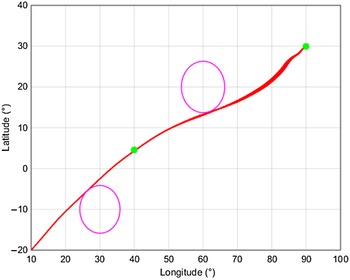
Figure 6 depicts the ground track with the no-fly zone strategy and without the no-fly zone strategy, respectively. It can be seen that without the no-fly zone strategy, the ground track will cross the no-fly zone, and with the no-fly zone strategy, the ground track will avoid the no-fly zone. So the geographic constraint is satisfied and the terminal position constraint is reached successfully. However, the flight time of the vehicle increases compared to the baseline case, this is because it has a longer voyage to avoid the no fly zones. For the attacker, long flight time may be unfavorable.
Ground track.

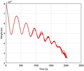
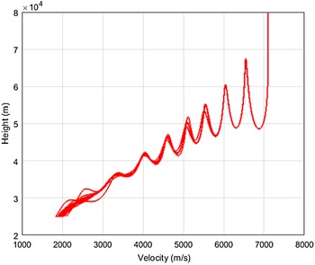
Figures 7 and 8 show the height profiles and velocity curves, it can be seen that the terminal height and the velocity satisfy the constraints. The flight-path angles and heading angles are shown in Figs 9 and 10. The flight-path angles are kept at relatively small values in the gliding phase. And the QEGC is also satisfied basically since there is no wide range fluctuation in the flight-path angles. The heading angles fluctuate in the gliding phase due to the changes of the sign of bank angle. Figures 11 and 12 display the changes of control variables. In the gliding phase, the angles of attack change according to the nominal angle-of-attack and the signs of bank angles change according the heading angle corridor. And the control constraints are also satisfied. Figure 13 gives the H-V profiles. It can be seen the heating rate, dynamic pressure and aerodynamic load constraints are satisfied and they are hard constraints which must be satisfied. The QEGC is soft constraint and the gliding trajectory may exceed the QEGC, this is because the lift-drag ratio of CAV-H is large and the angle-of-attack keeps high for a long time. To solve this problem, the author in literature [Reference Wang, Guo and Tang39] proposes a high order curve to describe the relationship between the height and velocity. The heating rates, dynamic pressures and aerodynamic loads are shown in Figs 14–16, respectively. All the path constraints are satisfied. Figure 17 shows the bang angle rate of the vehicle and there is no limit on it in the simulation.
Height profile.

Velocity curve.

Flight path angle.

Heading angles.

Bank angles.

Angle-of-attack.

H-V profile.

Heating rate.

Dynamic pressure.

Dynamic load.

Bank angle rate.

It can be seen from the above simulation results, the height of the vehicle has an oscillation which translates into undesirable cycling in heating rate, dynamic pressure and dynamic load, the oscillation can be suppressed by the following strategies:
 \begin{align}L\cos {\sigma _{pro}} = L\cos {\sigma _{ori}} - k\left( {\dot H - {{\dot H}_{ref}}} \right)\end{align}
Where
 ${\sigma _{ori}}$
is the bank angle proposed in this paper shown in (29),
 ${\sigma _{pro}}$
is the bank angle obtained by the improved strategy,
 $\dot H$
is the actual height change rate,
 ${\dot H_{ref}}$
is the reference height change rate,
 $k$
is the gain coefficient of height change rate, and the expression is as follows:
 \begin{align}k = {k_0} + \left( {\frac{{{e_0} - e}}{{{e_0} - {e_f}}}} \right)\left( {{k_f} - {k_0}} \right)\end{align}
In (39),
 ${k_0}$
,
 ${k_f}$
are the design parameters, which determine the damping of the system. The greater the difference is, the greater the system damping is and the smaller the height change rate is. In addition, the expression of reference height change rate
 $\dot{H}_{ref}$
is as follows:
 \begin{align}{\dot H_{ref}} = \frac{{r - {r_f}}}{{V - {V_f}}}\frac{{dV}}{{dt}}\end{align}
It should be pointed out that the oscillation of height is not conducive to the flight control, but it has good penetration characteristics.
In order to verify the accuracy and robustness of the proposed method under states deviation and parameters perturbation, 100 Monte Carlo simulations are performed for different random deviations and disturbances. The states deviation and parameters perturbation are subjected to normal distribution. The
 $3\sigma $
values are depicted in Tables 3 and 4.
States deviation of reentry vehicle

Parameters perturbation of reentry vehicle

The simulation results under disturbance conditions are shown in Figs 16–22. Figures 18–19 are the 100 simulation results, they depict that all the simulations will satisfy the terminal constraints and the no-fly zone constraint. Figures 22–24 are the parameters distribution. The longitude and latitude errors are almost within 0.2
 $^\circ $
. The velocities errors are within 150 m/s and the height errors are within 80 m. Notably, the simulation cut-off condition is to satisfy the height constrains, so the height errors are relatively small and subject to the distribution shown in Fig. 24. The simulations with deviations verify the effectiveness of the proposed method.
Height profiles.

Ground tracks.

Velocity curves.

H-V profiles.

Falling point distribution.

Velocities distribution.

Heights distribution.

5.0 Conclusions
In this paper, a trajectory planning algorithm based on predictor corrector algorithm is proposed for lifting-body entry vehicles with terminal states constraints and geographic constraints. The predictor corrector algorithm is based on a piecewise linear bank profile. This solves the problem of the mismatch between terminal range and height. For the geographic constraint, a bank angle reversal logic based on heading angle corridor is designed considering the influences of the no-fly zone. At last, the algorithm is verified with the CAV-H model. Simulation results show that this algorithm can generate an entry trajectory satisfying terminal constraints and geographic constraints. And the method has certain robustness under disturbances.
Acknowledgements
The authors would like to thank the staff in Beijing Institute of Electronic System Engineering for their assistance in carrying out the guidance law study.