INTRODUCTION
The intense electron-beam accelerator (IEBA) based on the blumlein line has been widely used in the applications such as high power microwave radiation (Gunin et al., Reference Gunin, Klimov, Korovin, Pegel, Polevin and Rostov1998), intense relativistic electron-beam generation (Mondal et al., Reference Mondal, Kumar, Roy, Mitra, Sharma, Singh, Rao, Mittal, Nagesh and Chakravarthy2007), and x-ray generation (Coogan et al., Reference Coogan, Davanloo and Collins1990). In the future, the developments of the intense electron-beam accelerator tend to be higher power, longer pulse width, and higher repetitive frequency. The interrelated technology of IEBA, such as pulse forming line (Zhang et al., Reference Zhang, Liu, Wang, Fan, Zhang and Feng2011; Cheng et al., Reference Cheng, Liu, Qian and Zhang2009), and pulse transformer (Liu at al., Reference Liu, Zhan, Zhang, Liu, Feng, Shu, Zhang and Wang2007) have been widely researched.
Most of researches on the radiation during the operation of IEBA focus on the field-emission diode, which is used as a load (Rokni et al., Reference Rokni, Cossairt and Liu2007; Vylet et al., Reference Vylet and Liu2002), and the radiations are generated by the high intensity electron beams go through the diode. Besides, high power gas switch is one of the basic components of IEBA for its advantages of simple structure, high power handling capability, and high dU/dt. Supposing that the voltage between the two electrodes of the gas switch is 30 kV, then, this value will reduce to zero in nearly 50 ns. So high intensity radiation is expected to be generated from the gas switch for high dU/dt or di/dt. This kind of radiation generated by gas switches have been researched in linear induction accelerator (Chen et al., Reference Chen, Ni and Li2009) and inductive energy storage accelerator (Zhong et al., Reference Zhong, Liu, Limin and Jianchun2008). Meanwhile, the faradic current in coaxial-cable has been used to discuss the level of this radiation. The result shows that the value of faradic current cannot be neglected. It will cause error in the accurate measurements of signals. And it is believed that the electromagnetic radiation will damage the health of the people that expose to it. However, the same research on the radiations generated by gas switches of intense electron-beam accelerator with capacitor energy storage is rarely reported. In addition, the investigations that mention above are limited to experimental studies. Theoretical analysis of the generation mechanism of electromagnetic field radiated by gas gap switches has not been presented.
In this paper, analysis aim at radiation of triggered spark-gap switch is put forward. The electromagnetic radiation during the operation of IEBA is measured. It is obtained that the amplitude of the radiation electric field is 753.4 V/m, the dominant frequency is 20.8 MHz, and the highest frequency is about 100 MHz. Furthermore, if the air pressure of the triggered spark-gap switch increases, the amplitude of the high frequency components will decrease.
SIMULATION AND THEORETICAL ANALYSIS
There are mainly two radiation sources, the high-frequency current flows through the triggered spark-gap switch and the electrons move from earth electrode to high-voltage electrode. The methods of circuit simulation and theoretical analysis are adopted to discuss them, respectively.
Structure of the IEBA
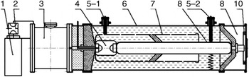
The structure of IEBA is shown in Figure 1 (Liu et al., Reference Liu, Cheng, Qian, Ge, Zhang and Wang2008). It consists of primary storage capacitor, triggered spark-gap switch, high voltage pulse transformer, main switch (gas gap switch), pulse forming line (PFL), and load resistance. The load resistance is a high power water resistor.
Structure of IEBA (1. Primary storage capacitor 2. Triggered spark-gap switch 3. High voltage pulse transformer 4. Main switch 5. Resistant divider 6. Outer cylinder of PFL 7. Spiral PFL 8. Inner cylinder 9. Load resistance 10. Inducing ring for current measurement.)

The accelerator operates as follows: first of all, the charging voltage of the primary storage capacitor increase, while the voltage comes into a certain value, the trigger gas switch is triggered by a high-voltage pulse and closes, then the energy-storage capacitor discharges to the primary winding of the transformer. Consequently, the transformer starts to charge the PFL. At the moment that the charging voltage of the PFL reaches the breakdown value of the main switch, the PFL discharges to the load resistance.
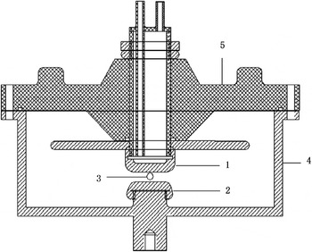
As the main switch is placed inside the PFL, its radiation signal is largely shielded. Contrarily, the triggered spark-gap switch is shielded by nothing, as is shown in Figure 1. Therefore, the radiation generated by the triggered spark-gap switch can be measured accurately. The structure of the triggered spark-gap switch is showed in Figure 2.
Structure of triggered spark-gap switch (1. High voltage electrode 2. Earth electrode 3. Trigger electrode 4. Outer housing 5. Top plate).

The main components of the triggered spark-gap switch used in this accelerator are high-voltage electrode, earth electrode, trigger electrode, top plate, and metal outer housing. The high-voltage electrode and the earth electrode are made from brass, while the top plate is made from nylon. The top plate is the exit of electromagnetic radiation.
Analysis of the Generation of Radiation
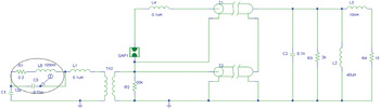
Figure 3 shows the circuit schematic of IEBA, where C1 is the primary storage capacitor, L1 is the inductance of primary circuit, TX2 is the pulse transformer, Gap1 is the main switch, T1 is the inner cylinder of PFL, T2 is the outer cylinder of PFL, R4 is the load resistance. The whole circuit is connected to components built in PSPICE component storage or modeled by the authors according to the performance of the device. Parameters of all components in the circuit are valued according to the practical circuit or theoretical calculation. The triggered spark-gap switch is modeled by its equivalent circuit elements, R1, L5, and C3, which are marked by a circle in Figure 3.
Circuit schematic of IEBA (C1 is the primary storage capacitor, L1 is the inductance of primary circuit, TX2 is the pulse transformer, Gap1 is the main switch, T1 is the inner cylinder of PFL, T2 is the outer cylinder of PFL, R4 is the load resistance.)

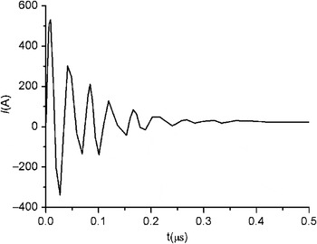
As the values of L1 and the inductance of the primary winding of the transformer are large, the frequency of the discharge current in L1 is low. However, the values of capacitor and inductance of triggered spark-gap switch are so small that there will be a high-frequency current passes the switch (current in C3) after the switch closes. The wave form of current in C3 is shown in Figure 4. (C1 is charged to 20 kV)
Wave form of current in C3.

According to the operation process of IEBA, when the switch closes, high-frequency current flows through the triggered spark-gap switch. And it is the origin of radiation. According to the Maxwell equations, the electric field radiated by high-frequency current is calculated as follow:
 $$\vec{E}=- \displaystyle{{{\rm \mu} l} \over {4{\rm \pi} r}}\displaystyle{\partial \over {\partial t}}\vec{I} \left(t - \displaystyle{r \over c} \right)$$
Where  $\vec{E}$ is the electric field at the measure point, l is the gap space between the high-voltage electrode and earth electrode of the triggered spark-gap switch, r is the distance from the central of the gas gap to the measure point,
 $\vec{I} $ is the current flows through the triggered spark-gap switch, c is the speed of light. According to equation (1), the electric field is determined by the variance ratio of current. And the frequency of the electric field is identical to
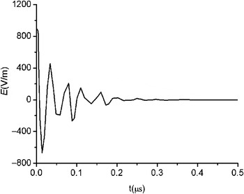
 $\vec{I} $. Using the Fourier transform, the frequency of the current flows through the triggered spark-gap switch is about 21 MHz. Furthermore, the electric field generated by the current shown in Figure 4 can be calculated using Eq. (1). The results are shown in Figure 5.
The electric field generated by the current shown in Figure 4.

Through all the analysis, the radiation source of triggered spark-gap switch is current flows through the triggered spark-gap switch. The dominant frequency should be 21 MHz, and it is determined by the current going through the switch.
EXPERIMENTAL RESULTS AND DISCUSSION
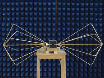
The radiation signal (Ur) is measured using the bi-cone antenna, the frequency range of which is from 20 MHz to 300 MHz. It is shown in Figure 6.
Structure of bi-cone antenna.

The far-field distance is determined by:
 $$R\gt \displaystyle{2\lpar D_1 + D_2 \rpar ^2 \over {\rm \lambda}}$$
Where D1 is the caliber of the bi-cone antenna, and D2 is the maximum diameter of the radiation source. λ is the wave length of the measured radiation. Here, D1 is 1m, and D2 is 0.2 m. According to the theoretical analysis, the maximum frequency is nearly 100 MHz. So the far-filed distance is 0.96 m. And during this experiment, the antenna is put at the distance of 10 m.
The current in primary circuit (Ip) and the charging voltage of PFL (Up) are also measured. As is illustrated in Figure 7. The primary storage capacitor is charged to 20 kV, and the air pressure of the triggered spark-gap switch is 0.25 MPa.
Result of measurement (Ip is the current in primary circuit, Up is the charging voltage of PFL, and Ur is radiation signal).

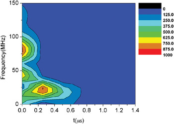
According to the operation process of the IEBA and the relationship of Ip, Up and Ur in Figure 7, it is clear that, when the triggered spark-gap switch close, the primary circuit begin to discharge, and the PFL begin to be charged, when the charging voltage of the PFL reaches the self breakdown value of the main switch, the PFL discharged to the load resistance, the charging process over, Up tends to be zero gradually. Therefore, high intensity radiation generate at the moments that the triggered spark-gap switch and main switch close, as is shown in Ur. The amplitude of the radiation reaches to nearly 753.4 V/m. This value is a little smaller than the simulation result shown in Figure 5 for the attenuation of signal in the air and the shielding of the outer housing of triggered spark-gap switch. Frequency analysis and time-frequency analysis are taken to the radiation signal induced by the triggered spark-gap switch, the first section of Ur. As are shown in Figures 8 and 9.
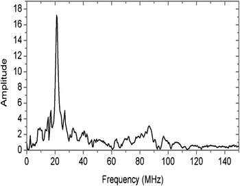
Frequency spectra of radiation induced by the triggered spark-gap switch.

Time-frequency analysis of radiation.

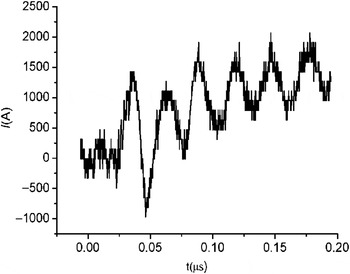
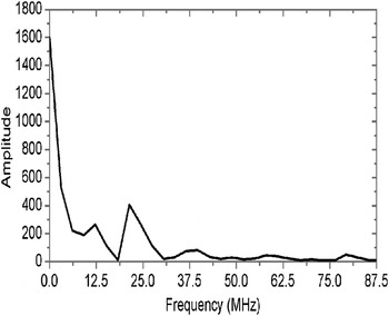
As is shown in Figure 8, the dominant frequency is 20.8 MHz, and the highest frequency is nearly 100 MHz. The experimental result validates simulation and theoretical analysis results very well. According to the time-frequency analysis result, in the initial time after the triggered spark-gap switch close, the frequency band is very wide. The wide-band radiation last for nearly 200 ns. It is of great significance to research about this mechanism, and it provides a new method of wide-band microwave radiation. Furthermore, the current that flows through the triggered spark-gap switch is measured. Figure 10 shows the result. And the frequency spectra are shown in Figure 11.
The current that flows through the triggered spark-gap switch.

Frequency spectra of the current that flows through the triggered spark-gap switch.

It is clear that there is a high-frequency current flow through the triggered spark-gap switch, and 21.3 MHz is a resonance point. It is nearly the same as the radiation signal. That is to say, the radiated electric field is mostly generated by the current flows through the switch. This validates the simulation results further.
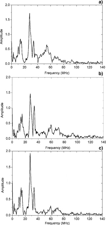
Another interesting phenomenon is observed during the experimental study. The air pressure of the triggered spark-gap switch change from 0.2 MPa to 0.3 MPa and the primary storage capacitor is charged to 20 kV. The switch is replaced by another one with different size. The frequency analysis results of the radiation induced by the triggered spark-gap switch are shown in Figure 12.
Frequency spectra of radiation induce by the triggered spark-gap switch in different air pressure (a. 0.2 MPa b. 0.25 Mpa c. 0.3 MPa).

As the analysis results show, the dominant frequency is determined by the circuit of IEBA. As we change the triggered spark-gap switch, its equivalent circuit elements varies. The dominant frequency varies from 20.8 MHz to 27 MHz. And the dominant frequency makes no difference when the air pressure changes.
The interesting phenomenon is, accompanying with the increase of the air pressure (from 0.2 MPa to 0.3 MPa), the amplitude of high frequency components (larger than 50 MHz) of the radiation signal decreases. This phenomenon is worthy to be discussed.
A group of electrons that move with shifting speed will induce radiation (Joseph et al., Reference Joseph and Ercument1997; Guo, Reference Guo1995). The brief analysis is advanced as follows. Supposing that the electrons in the gap of the switch move as a group, and the electric field accelerates them; the head of the group is a plane. Electromagnetic radiation induced by a single electron is given by (Guo, Reference Guo1995)
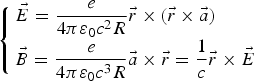 $$\left\{\matrix{\vec{E}=\displaystyle{e \over {4{\rm \pi} {\rm \varepsilon} _0 c^2 R}}\vec{r} \times \lpar \vec{r} \times \vec{a} \rpar \cr \vec{B} = \displaystyle{e \over {4{\rm \pi} {\rm \varepsilon} _0 c^3 R}}\vec{a} \times \vec{r}=\displaystyle{1 \over c}\vec{r} \times \vec{E} } \right.$$
Where R is the distance from electron to measure point,  $\vec{r}$ is the unit vector of R, c is the speed of light. If we discuss the measure point which is perpendicular to the gap of the triggered spark-gap switch, we have
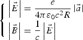 $$\left\{\matrix{\left\vert {\vec{E} } \right\vert =\displaystyle{e \over {4{\rm \pi} {\rm \varepsilon} _0 c^2 R}}\left\vert {\vec{a} } \right\vert \cr \left\vert {\vec{B} } \right\vert =\displaystyle{1 \over c}\left\vert {\vec{E} } \right\vert } \right.$$
At the point that is 10 m far from the gas gap, the electric field is given by
 $$\left\vert \vec{E} \right\vert = \displaystyle{e \over 4{\rm \pi} {\rm \varepsilon} _0 c^2 R} \left\vert \vec{a} \right\vert = 1.6 \times 10^{ - 27} \left\vert {\vec{a} } \right\vert$$
That is to say, the amplitude of electric field is determined by the acceleration of electron. Suppose that the distance from high-voltage electrode to earth electrode is d, the charging voltage is U, mass of electron is m e, the velocity of electron is v, then
 $$qE^{\prime} = m_e a$$
where E′ is the electric field between the head of the electron-group and the high-voltage electrode. It can be calculated as follow
 $$E^{\prime} = \displaystyle{U \over d - vt}$$
Where the influence of the collision in the switch gap is indicated by the parameter, t. t is the moving time of the electrons. The value of t is from zero to the close time of the switch. It is determined by the charging voltage, the gap distance, and air pressure in the gap. t is essential to the spectra.
Then, the acceleration is
 $$a = \displaystyle{qU \over m_e \lpar d - vt\rpar }$$
Therefore, the radiation electric fields is
 $$\left\vert \vec{E} \right\vert = 1.6 \times 10^{- 27} \displaystyle{qU \over m_e \lpar d - vt\rpar }$$
According to equation (7), with the moving of electron-group (t increase), the acceleration of electron increases. Through all the analysis above, we can draw the conclusion that the electric field increases when electron-group move from earth electrode to high-voltage electrode. The rise time of radiation signal is nearly equal to the close time of triggered spark-gap switch. The highest frequency is inverse proportional to the rise time. In this experiment, as the air pressures in the triggered spark-gap switch increases, the close time will increases (Cheng et al., Reference Cheng, Liu and Qian2010). Then, the high frequency components decrease.
CONCLUSIONS
The electromagnetic radiation during the operation of intense electron beam accelerator is studied in this paper. Circuit simulation of IEBA is presented. Results of experimental study agree with the analysis very well. There are two radiation sections at the time when triggered spark-gap switch closes and main switch closes. The radiation of the triggered spark-gap switch is studied carefully. The frequency spectra analysis is carried out. The dominant frequency is 20.8 MHz, and the highest frequency is nearly 100 MHz. In addition, the change of spectra with the increase of air pressure is studied. Accompanying with the changes of air pressure, the amplitude of high frequency components of the radiation decreases, and the dominant frequency make no difference. And it is discussed. The time-frequency analysis of the radiation signal reveals that the gas gap switch can be used as a source of wide-band microwave radiation. Further study on this problem is of great value.