1. Introduction
Developing a rotorcraft with automatic searching, positioning, tracking and landing capabilities that can be redirected to a designated ship at sea after the completion of its mission, such as monitoring, delivery of the object, and offshore operation, is a great challenge. Rotorcraft capable of searching, positioning and tracking ships can be used to detect and monitor ships. Such capabilities can also be used by rotorcraft for taking-off from and landing on a pitching and heaving ship's deck. Manned helicopters depend on the technical ability of the pilot to search, position and track the deck marks, while unmanned rotorcraft depend on equipment attached to the deck, such as radar or relative global positioning system (GPS) to position and track the deck.
Various methods have emerged over the years for positioning and tracking ships, such as relative or augmented GPS/GNSS with two-way data link, radar, infrared (IR) and visible light camera, and light detection and ranging (LIDAR). Kelly (Reference Kelly2013) used shipborne GPS and ship-to-unmanned aerial vehicle (UAV) communication for precise positioning and execution of commands. Pervan et al. (Reference Pervan, Chan and Colby2003) and Gold and Brown (Reference Gold and Brown2004) also used relative GPS for tracking and positioning the deck of the ship. Sierra Nevada Corporation (2008) developed a radar system called universal automatic recovery system for relative attitude estimation. Northrop Grumman Firescout and Bell Eagle Eye used a system consisting of a millimetre wave radar on the ship and a transponder on the UAV. Yakimenko et al. (Reference Yakimenko, Kaminer, Lentz and Ghyzel2002) proposed the application of an IR camera to track a ship from a long distance based on information from an IR image, with the aid of GPS and data link at close range. On the contrary, Xu et al. (Reference Xu, Zhang, Ji, Cheng and Tian2009) proposed the employment of GPS and data link for long-range positioning of the ship and the application of an IR camera on the ship's deck for close tracking. Chaves et al. (Reference Chaves, Wolcott and Eustice2015) proposed to use a visible light camera and some markers on the ship's deck to track and land. Richardson et al. (Reference Richardson, Jones, Likhoded, Sparks, Jordan, Cowling and Willcox2013) proposed a camera for landing on a moving platform. Garratt et al. (Reference Garratt, Pota, Lambert, Eckersley-Maslin and Farabet2009) suggested a system with a rotating LIDAR and a beacon for estimation of the ship's attitude at short range. Arora et al. (Reference Arora, Jain, Scherer, Nuske, Chamberlain and Singh2013) also proposed using a camera to track the ship's deck in good light conditions and LIDAR to track the ship's deck in adverse light conditions, respectively. Automatic Identification System (AIS) data is another useful source of information to aid in maritime navigation and situation awareness (Zhou et al., Reference Zhou, Chen and Zhang2020; Alizadeh et al., Reference Alizadeh, Alesheikh and Sharif2021; Wen et al., Reference Wen, Li and Zhao2022), and the fusion of the AIS data and other sensor data can improve the abilities of the rotorcraft and the ship. Liu et al. (Reference Liu, Guo, Nie, Hu, Xiong, Yu and Guizani2022) proposed an intelligent edge-enabled lightweight neural network and developed a camera and AIS data fusion-based augmented reality system using multi-source data fusion framework to enhance the situation awareness of autonomous surface vehicles. Liu et al. (Reference Liu, Liu, Gunawan and Bucknall2021) proposed a fuzzy logic-based multi-sensor data fusion algorithm for detection of moving target ships by using both AIS and radar information, and a two-stage fuzzy logic association method was developed and integrated with Kalman filtering to achieve a computationally efficient performance.
The main performance indicators of the relative or augmented GPS/GNSS are user range error (URE), user range rate error (URRE), user range acceleration error, universal time coordinated offset error, horizontal positioning accuracy and elevation positioning accuracy. All of these perform better than the requirements of the standard, for example, URE is 1 · 3 m, URRE is 2 · 63 mm/s, the horizontal positioning accuracy is 1 · 25 m, etc. The main performance indicators of radar are radar wavelength, radar beam width, detection range, range resolution, range accuracy, velocity measurement range, velocity resolution, velocity accuracy, angle measurement range, angle resolution and angle accuracy, and they are the basis for selecting or designing a radar to meet application requirements. However, the relative or augmented GPS/GNSS, radar or AIS is susceptible to signal blockage from the superstructure of the ship, multipath errors and jamming, resulting in a drop in GPS/GNSS, radar or AIS performance or even failure. The main performance indicators of IR and visible light cameras are spatial resolution, pixel size, band range, quantum conversion efficiency, exposure time and frame rate, and these are also the basis for selecting or designing IR or visible light camera to meet application requirements. The distance between ship and unmanned rotorcraft cannot be determined by IR or visible light camera, and both will fail under adverse lighting conditions such as a glare from sunlight on the water, fog or rain. Besides, expensive infrastructure must be installed on-board the ship and a data link between the unmanned rotorcraft and the ship's deck is also required when using the methods based on GPS/GNSS or radar. Cargo ships are not designed to be landed on without expensive on-board infrastructure such as GPS/GNSS or radar. The same applies for the methods based on IR or visible light camera that require special beacons or patterns to be placed on the deck of the ship. In addition, active radiation sources such as radar, IR or visible light beacons pose a risk to a ship in tactical situations.
The main performance indicators of LIDAR are laser wavelength, detection range, range accuracy, emitted laser beam width, field of view of receiving laser (angle measurement range), angle resolution, laser rotation method, etc. It can be seen from the above description of radar that most of the main performance indicators of LIDAR are the same as or similar to those of radar. Thus, radar can be used in most applications of LIDAR, especially in detecting aerial targets. But LIDAR installed on the rotorcraft cannot be replaced by millimetre wave radar in the application of rotorcraft searching, positioning, tracking and landing on ships at sea because the beam width of millimetre wave radar is much larger than the laser beam width of LIDAR. The ship is seen as a point target at long range and a body target at close range. As a result, radar installed on the rotorcraft cannot be used for landing on the ship at close range. The methods based on LIDAR have many advantages such as high angle resolution and range accuracy (Liu et al., Reference Liu, Atia, Karamat and Noureldin2015). However, the LIDAR equipment currently used on rotorcraft has some shortcomings, such as a limited range of detection, high price, etc. For example, in Garratt et al. (Reference Garratt, Pota, Lambert, Eckersley-Maslin and Farabet2009) the LIDAR had a laser transmitting power of 20 mW and no advanced signal processing algorithm was employed. Thus it could only be used for the landing of rotorcraft within a range of 0 · 03 m–16 · 5 m from the ship's deck. The LIDAR in Arora et al. (Reference Arora, Jain, Scherer, Nuske, Chamberlain and Singh2013) has four-channel laser beams, 180° vertical nodding field of view (FOV), 85° horizontal FOV and working range of 100 m. However, the size of this equipment is 432 mm × 361 mm × 203 mm and the mass is 13 · 6 kg. Consequently, this LIDAR could only be used on large helicopters for tracking and landing.
This study proposes the use of a dual-channel LIDAR searching, positioning, tracking and landing system (DCLSPTLS) for rotorcraft applied to ships at sea. The system is mainly composed of two semiconductor lasers, two avalanche photodiodes (APDs), an 80 MHz high-speed analogue to digital (AD) converter, a stepper motor, a pulse encoder and a signal processor. The laser echoes in different directions are received by two APDs, and the 80 MHz high-speed AD converter samples the analogue signal output by the two APDs at the same time and converts them into digital signals to the signal processor. The stepper motor is used to rotate the DCLSPTLS lateral laser beam, and the pulse encoder can acquire the rotation angle of the steeper motor to the signal processor. The signal processor retrieves two-channel ranging information and the rotation angle of the steeper motor and utilises them to obtain the azimuth angle and the distance of the ship relative to the rotorcraft, the ship's course, the total tracking time, the direction of the rotorcraft tracking speed, and the pitch and roll angle of the ship's deck relative to the rotorcraft. The multi-pulse laser echoes accumulation method is implemented in the signal processor when DCLSPTLS needs to increase the detection range, and the signal processor also recognises whether the laser echo comes from the ship's deck or the sea surface based on the accumulated number of laser echoes and the physical phenomenon that the laser reflectivity of the ship's deck in the near-IR band is four orders of magnitude higher than that of the sea surface.
The DCLSPTLS searching and positioning model is established to obtain the simulation ranging values of DCLSPTLS lateral channel laser beam by formulating the lateral channel laser detection equation. The midpoint connection method in the DCLSPTLS searching and positioning model is proposed to obtain the ship's course by forming two vectors from the midpoints of the scan arc in the ship and comparing the scan arc length with the ship's length. Using the above parameters as the input, a better tracking trajectory is designed by the DCLSPTLS tracking model. The DCLSPTLS landing model can calculate the pitch and roll angles of the ship's deck relative to the rotorcraft by using the least squares method and laser irradiation coordinates. Simulation and an actual rotorcraft flight measurement experiment verify the effectiveness of DCLSPTLS.
2. DCLSPTLS hardware architecture
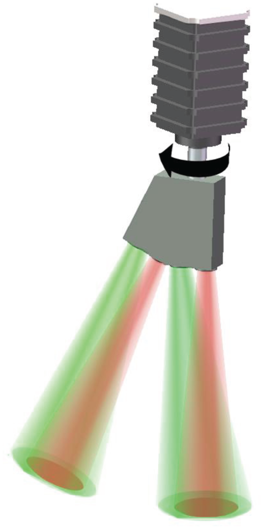
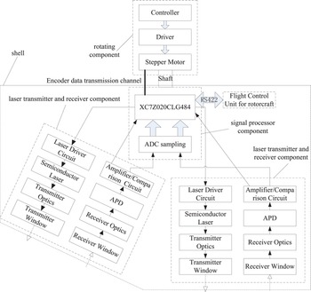
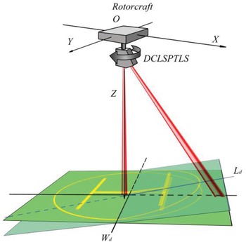
As shown in Figure 1, DCLSPTLS is mainly composed of a dual-channel LIDAR and a rotating component, where the red part is the transmitter laser beam and the green part is the detecting FOV. The dual-channel LIDAR has two sets of transmitter and receiver components, each of which can emit a laser beam with a 1 mrad divergence angle and receive a laser echo with the detection FOV slightly larger than the laser divergence angle. One laser beam is vertically illuminated on a ship/sea surface to determine whether the rotorcraft is above the ship and to measure the height of the rotorcraft from the ship/sea surface. The other laser beam is fixed at a certain angle with the vertical channel laser beam, and it can measure the lateral distance and azimuth of the ship relative to the rotorcraft and the ship's course during the searching stage, obtain the tracking speed and direction of the rotorcraft according to the ship positioning results during the tracking stage, and measure the attitude of the ship's deck relative to the rotorcraft during the landing stage by using the rotating component. In addition, the dual-channel LIDAR adopts miniaturised optical and circuit design methods and special signal processing methods, leading to advantages of small size, light weight and long detection range. Figure 2 is a block diagram of the composition of the DCLSPTLS hardware. Besides the two sets of laser transmitter and receiver components and rotating component, a set of signal processor component and shell component are also included.
DCLSPTLS schematic map

DCLSPTLS block diagram

Each laser transmitter and receiver component includes a laser transmitter subsystem and a laser receiver subsystem. The laser transmitter subsystem is composed of a laser driving circuit, a semiconductor laser, a transmitter optics and a transmitter window, which perform the functions of laser control, pulse shaping, beam shaping and protection of internal optical component, respectively. The laser receiver subsystem is composed of a receiver window, a receiver optics, an avalanche photodiode (APD) and amplification/comparison circuit, which perform the functions of protection of internal optical components, receiving backscattered laser echo, photoelectric conversion, electrical signals amplification and comparison, respectively.
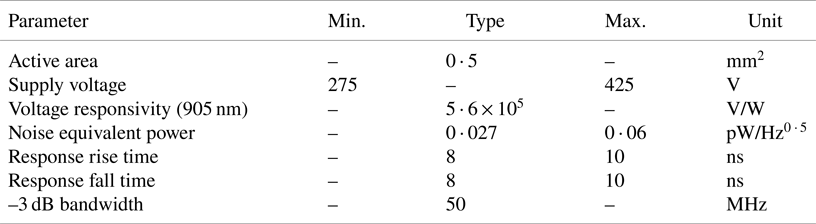
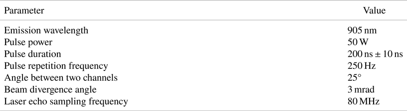
In order to meet the requirements of rotorcraft searching, positioning, tracking and eye-safety (Sabatini and Richardson, Reference Sabatini and Richardson2003; Sabatini et al., Reference Sabatini, Richardson, Jia and Zammit-Mangion2012), a semiconductor laser is applied to DCLSPTLS as the laser source, the parameters of which are shown in Table 1. APD is selected mainly for its high voltage response and low noise, and should maximise the sensitivity of the laser receiving subsystem. The parameters are shown in Table 2.
Laser parameters

Avalanche photodiode parameters

The signal processor component is composed of a field programmable gate array (FPGA) circuit, an ADC sampling circuit with 80 MHz sampling frequency, a high-speed memory, and a RS-422 communication circuit. The signal processor component can realise the generation of electric pulse signal, the AD conversion of the electric laser echo signal, the digital accumulation of multiple laser pulse echoes, the calculation of distance by measuring the laser flight time, the calculation of the rotation angle by counting the pulses from the photoelectric encoder in the rotating component, the calculation of the ship deck attitude and the calculation of the height from the rotorcraft to the ship deck or the sea surface, and the storage and transmission of the solved information.
The rotating component is composed of a stepper motor, a driver and a controller. The stepper motor is used to rotate the dual-channel LIDAR and is equipped with a photoelectric encoder which outputs 1,000 pulses if the motor shaft rotates 360 degrees. The controller is applied to output the pulse signal to control the motor stepping speed and steering. The driver is used to generate the two differential signals which can drive the stepper motor by receiving the pulse signal from the controller, and it can receive the differential signal output from the encoder.
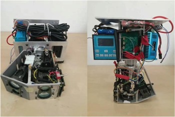
The DCLSPTLS prototype with a size of 185 mm × 100 mm × 260 mm and a weight of 3 · 2 kg is shown in Figure 3. The size and weight of the dual-channel LIDAR as a part of the DCLSPTLS are 130 mm × 120 mm × 70 mm and 0 · 6 kg, respectively. The angle between the lateral channel laser beam and the vertical channel laser beam is 25°. A prototype DCLSPTLS is used to verify the effectiveness of the DCLSPTLS. Its rotating component has many parts that can be optimised. For example, the driver of the rotating component can be replaced with only one drive circuit board, and the controller can be integrated into FPGA.
DCLSPTLS principle prototype

3. DCLSPTLS workflow and modelling
3.1 DCLSPTLS detection range
Zeng et al. (Reference Zeng, Wang, Wei, Cheng, Zheng, Feng and Shan2021) found that the 1,064 nm laser reflectivities of the deck, the Yangtze River surface and the sea surface are 0 · 27, $1 \cdot 08 \times {10^{ - 4}}$ and $2 \cdot 84 \times {10^{ - 5}}$
 , respectively. Although the laser wavelength used in this paper is 905 nm, it belongs to the near-IR band within the 1,064 nm wavelength. Therefore, it can be considered that the laser reflectivity at the 905 nm wavelength is approximately equal to that at the 1,064 nm wavelength. The laser reflectivities are the theoretical basis of the reliable identification of the ship and the sea surface and the design of the DCLSPTLS.
The laser detection distance of the small view field R can be expressed as:

where ${P_t}$ is the transmitting power, $\rho$
 is the laser reflectivity, ${A_r}$
 is the effective receiving aperture, ${\tau _r}$
 is the transmittance of the receiving optical system, ${\tau _t}$
 is the transmittance of the transmitting optical system, and ${\tau _u}$
 is the transmittance of the one-way transmission path. The parameters are: ${P_t} = 50\,W$
 , ${A_r} = \pi \times {({15 \times {{10}^{ - 3}}} )^2}{m^2}$
 , ${\tau _t} = 0 \cdot 8$
 , ${\tau _r} = 0 \cdot 8$
 . In the case of 25 km visibility, ${\tau _u} = exp ({ - 3 \times {{10}^{ - 4}} \cdot R} )$
 . ${P_{r\min }}$
 is the minimum detectable power and can be expressed as:

where NEP is the equivalent noise power, SNR is the signal-to-noise ratio, and $\Delta B$ is the receiving bandwidth. It can be seen from Table 2 that $\textrm{NEP} = 0 \cdot 027\,\textrm{pW}/\sqrt {\textrm{Hz}}$
 and $\Delta B = 50\,\textrm{MHz}$
 . If SNR = 7 dB then, according to Equation (2), ${P_{r\min }} = 9 \cdot 54 \times {10^{ - 10}}W$
 .
For the deck, $\rho = 0 \cdot 27$ . The detection distance of the single-pulse laser is 1,045 m, according to Equation (1). For the sea surface, $\rho = 2 \cdot 84 \times {10^{ - 5}}$
 . The detection distance of the single-pulse laser is 14 · 6 m according to Equation (1).
When the detection distance of the single-pulse laser does not meet the requirement, the multi-pulse laser echoes accumulation method is used to increase the detection distance. Suppose that the signal $\zeta (t )$ output from the amplifier circuit is:

where $s(t )$ is the target echo signal and $n(t )$
 is the noise signal. Accumulating multiple pulse signals can be expressed as:

In Equation (4), N is the number of echo pulses. After multiple superpositions, the target echo signal is enhanced and the noise is suppressed due to correlation, so that the target echo signal is highlighted from the noise and the SNR is improved. Theoretical analysis shows that the power SNR of multiple pulses can be increased by $\sqrt N$ times that of the SNR of the single pulse ratio after N pulses are superimposed and correlated (Zhong and Li, Reference Zhong and Li2006).
In order to increase the detection distance from the DCLSPTLS to the ship's deck to 2,000 m, the laser echo power is ${P_r} = 1 \cdot 46 \times {10^{ - 10}}W$ according to Equation (1). In order to achieve the ${P_{r\min }}$
 of the design above, there is:

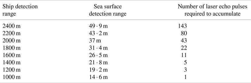
The minimum number of accumulated pulses N is 43, according to Equation (5). Table 3 is compiled for ease of use. The DCLSPTLS accumulates according to the number of laser pulses in Table 3, and it can output laser echoes with a 7 dB power SNR.
Corresponding table of detection range and number of laser echo pulses required to accumulate

3.2 DCLSPTLS workflow
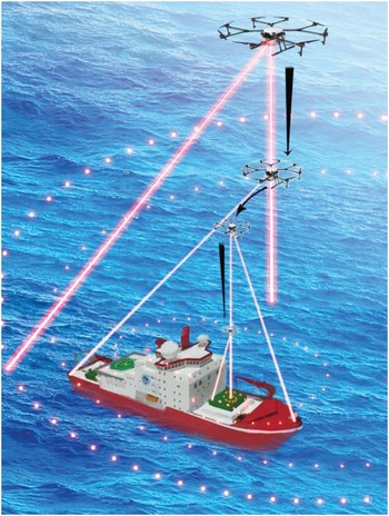
Figure 4 is a schematic diagram of the rotorcraft using the DCLSPTLS which is installed in the rotorcraft to search, position, track and land on a ship. The whole process is elaborated as follows:
(a) Searching and positioning process. Since the laser reflectivity of the ship's deck in the near-IR band is four orders of magnitude higher than that of the sea surface, the peak of the ship's laser echo is 100 times the peak of the sea surface laser echo. By setting the appropriate threshold for the peak of the laser echo, the DCLSPTLS can reliably distinguish the ship from the sea surface, and obtain the distance and angle of the ship relative to the rotorcraft. At the same time, the multi-pulse laser echoes accumulation method is adopted to increase the detection distance of the DCLSPTLS. The specific approach is as follows. Since the DCLSPTLS can sample N laser echoes when the lateral channel laser beam rotates one circle, the k adjacent laser echoes in each circle are added and the sliding window method is adopted. Since the k adjacent ship/sea surface laser echoes are highly correlated and the noise correlation is low, the calculation will greatly improve the SNR of ship/sea surface echoes. The failed peak value of the original laser echo will be effective again using the multi-pulse laser echoes accumulation method, thereby obtaining the distance and angle of the ship relative to the rotorcraft. Of course, the price is a reduction in the angular resolution of the ship.
It should be noted that the ship must be within the range of the farthest horizontal detection distance of the DCLSPTLS. Under this condition, the rotorcraft descends from its maximum flight height, meanwhile the lateral channel laser beam of the DCLSPTLS is used to detect the ship. When the lateral channel of the DCLSPTLS obtains the distance information and angle information of the ship for the first time, it records them and the rotorcraft will hover in the air for a period of time. After the hovering time, the rotorcraft rises quickly. If the lateral channel of the DCLSPTLS obtains the information of the ship during the rising time, it means that the ship is just moving away from the rotorcraft. If there is ship information during the hovering period and there is no information during the rising time, it means that the ship is stationary. The rest of the conditions indicate that the ship is travelling in a direction approaching the rotorcraft. The rotorcraft then descends rapidly for a period of time and records the ship information until the lateral channel of the DCLSPTLS is not able to obtain the ship information.
Rotorcraft searching, positioning, tracking and landing on a ship using DCLSPTLS

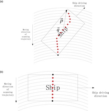
Figure 5 shows two kinds of scanning trajectories of the lateral channel laser beam of the DCLSPTLS on a ship. Figure 5(a) is the trajectory of the general ‘scan arc length’ and Figure 5(b) is the trajectory of the longest ‘scan arc length’. ‘Scan arc length’ refers specifically to the arc length in a circle obtained by irradiating on a ship with the lateral laser beam, and the general ‘scan arc length’ refers specifically to the arc length in the middle of all ‘scan arc lengths’.
Two kinds of ship scanning trajectories: (a) scanning trajectory of general ‘scanning arc length’, (b) scanning trajectory of the longest ‘scanning arc length’
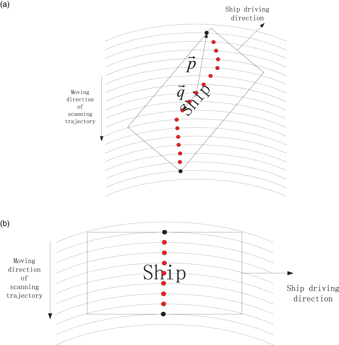
It can be seen from Figure 5(a) that the midpoint of the scan trajectory of the general ‘scan arc length’ and the midpoint of the scan trajectory of the previous arc length form a vector $\vec{q}$ and its direction is exactly the same as or opposite to the ship's course. The midpoint of the scan trajectory of the general ‘scan arc length’ and the coordinate points of the ship then obtained for the first time form a vector $\vec{p}$
 , and the angle between the above two vectors is calculated. If the ship is travelling away from the rotorcraft and the angle between $\vec{p}$
 and $\vec{q}$
 is an acute angle, then the ship's course is consistent with the direction of the vector $\vec{q}$
 . If the ship is travelling away from the rotorcraft and the angle between $\vec{p}$
 and $\vec{q}$
 is an obtuse angle, then the ship's course is opposite to the direction of the vector $\vec{q}$
 . If the ship is travelling towards the rotorcraft and the angle between $\vec{p}$
 and $\vec{q}$
 is an acute angle, then the ship's course is opposite to the direction of the vector $\vec{q}$
 . If the ship is travelling towards the rotorcraft and the angle between $\vec{p}$
 and $\vec{q}$
 is an obtuse angle, then the ship's course is consistent with the direction of the vector $\vec{q}$
 . This method of estimating the ship's course is called the ‘midpoint connection method’.
It can be seen from Figure 5(b) that if the ship's course is vertical to the moving direction of the scanning trajectory, then the ‘midpoint connection method’ will be invalid. Therefore, when the ‘scan arc length’ is close to the length of the ship, the rotorcraft flies at the maximum horizontal flight speed to the midpoint of the ‘scan arc’. If the vertical channel laser beam of the DCLSPTLS irradiates on the ship during the horizontal flight, it means that the rotorcraft is near the ship and happens to complete the searching and tracking tasks. If the vertical channel laser beam of the DCLSPTLS irradiates on the sea surface after the horizontal flight, the rotorcraft will restart the searching mission and the ship's course is the same as or opposite to the moving direction of the scanning trajectory.
(a) Tracking process. When the rotorcraft detects and acquires information on the distance, angle and speed of the ship at a long distance, the tracking scheme for predicting the ship's trajectory is applied to tracking the ship. The ship's course has been obtained through the searching process. Assuming that the ship's course is unchanged, the typical speed of the ship, the range of the rotorcraft speed and the range of the oblique flight angle of the rotorcraft are considered to estimate a tracking trajectory which is utilised by the rotorcraft to track the ship. Section 4.2 describes how to estimate the tracking trajectory.
When the rotorcraft tracks the ship, the vertical channel laser beam of the DCLSPTLS is used to determine whether there is a deck in the vertical direction of the rotorcraft. When the rotorcraft is far away from the ship, one laser irradiation of the vertical channel laser beam of the DCLSPTLS alone is insufficient to obtain the distance information. Similarly, the multi-pulse laser echoes accumulation method is utilised by the vertical channel of the DCLSPTLS to increase its detection distance.
(a) Landing process. In the process of continuous tracking of the ship by the rotorcraft, if the vertical channel laser beam of the DCLSPTLS has been irradiated on the ship, it means that the rotorcraft is nearly above the ship. At that moment, the rotorcraft will use its own camera to observe the apron on the deck and fly to the vicinity of the apron. After that, each time the lateral channel laser beam of the DCLSPTLS rotates one circle, it will accumulate information on the distance and angle of the deck.
The lateral channel of the DCLSPTLS will accumulate a certain amount of information on the deck distance and angle every time it rotates, and the rotorcraft flight control module will calculate the deck attitude information in real time and adjust the rotorcraft attitude. The rotorcraft then descends a certain distance. At the same time, the vertical channel of the DCLSPTLS continuously acquires the height information of the rotorcraft in order to determine whether the rotorcraft can land on the ship. The above process is repeated until the rotorcraft lands smoothly on the ship's deck.
3.3 DCLSPTLS searching and positioning model
The DCLSPTLS searching and positioning model is established to determine the distance, angle and course of the ship relative to the rotorcraft. When the rotorcraft is locked on the target ship, the ship is tracked by the rotorcraft in a relatively optimised way.
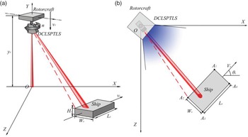
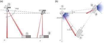
As shown in Figure 6, the geodetic coordinate system OXYZ is established with the projection point of the rotorcraft on the sea surface as the coordinate origin O, where the positive direction of the Y-axis is perpendicular to the sea surface and upward, the positive direction of the Z-axis is horizontal to the sea surface and southward, and the positive direction of the X-axis is determined by the right-hand rule. In the XZ plane, the angle from the positive X-axis to the positive Z-axis along the clockwise direction is positive. The XOZ plane is equivalent to the sea surface. The ship whose length, width and height are ${L_s}$ , ${W_s}$
 and ${H_s}$
 respectively are simplified into a cube. At the beginning, the coordinates of the centre point of the deck are $({{x_s},{H_s},{z_s}} )$
 and the angle between the deck length direction and the positive direction of the X-axis is ${\theta _s}$
 . The coordinates of the four endpoints of the deck ${A_1}$
 , ${A_2}$
 , ${A_3}$
 and ${A_4}$
 are as follows:

where $m = 1,2,3,4$ , ${\alpha _1} = \arctan ({{W_s}/{L_s}} )$
 , ${\alpha _2} = \pi - {\alpha _1}$
 , ${\alpha _3} = \pi + {\alpha _1}$
 , ${\alpha _4} = 2\pi - {\alpha _1}$
 . The ship travels along the deck length direction and the sway of the deck during the searching process are not considered. The angle between the driving speed ${V_s}$
 and the Y-axis is zero, and the angle between the ${V_s}$
 and the X-axis is ${\theta _s}$
 . At the beginning, the angle between the direction of the rotorcraft nose and the positive direction of the X-axis is ${\theta _0}$
 , and the direction of the rotorcraft nose is the same as the deck width direction. The DCLSPTLS is placed in the rotorcraft and rotates clockwise. The initial direction of the DCLSPTLS lateral channel laser beam is consistent with the direction of the rotorcraft nose. The angle between the DCLSPTLS lateral channel laser beam and the vertical channel laser beam is ${\theta _D}$
 . The rotorcraft is within the height range in which the DCLSPTLS lateral channel can detect the ship. The initial coordinates of the rotorcraft at the beginning are $({0,{y_r},0} )$
 . The rotorcraft falling speed ${V_r}$
 is vertically downwards along the Y-axis and the DCLSPTLS rotates clockwise at speed n. The lateral channel laser emission frequency is ${f_{\textrm{side}}}$
 , and the farthest detection distance of the ship by lateral channel laser is ${L_{s\max }}$
 . The simulation time step is $\Delta t = 1/{f_{\textrm{side}}}$
 .
DCLSPTLS searching and positioning model diagram: (a) three-dimensional stereogram, (b) top view

The coordinates of the DCLSPTLS lateral channel laser beam irradiation point on the sea surface are:

where r is the scan radius, t is the rotation time and ${\theta _0}$ is the initial angle of the DCLSPTLS. The DCLSPTLS searching model is established as follows.
1 When $t = a\Delta t({a = 0,1,2, \ldots ,{j_1}} )$
 , then $r = ({{y_r} - {V_r}a\Delta t} )\tan {\theta _D}$. By putting them into Equation (7), Equation (7) can be represented by Equation (8) as follows:
(8)\begin{equation}\left\{ {\begin{array}{@{}l} {x = ({{y_r} - {V_r}a\Delta t} )\tan {\theta_D}\cos ({2\pi na\Delta t + {\theta_0}} )}\\ {y = 0}\\ {z = ({{y_r} - {V_r}a\Delta t} )\tan {\theta_D}\sin ({2\pi na\Delta t + {\theta_0}} )} \end{array}} \right.\end{equation}



By connecting the coordinates represented by Equation (8) to the coordinates $({0,{y_r} - {V_r}a\Delta t,0} )$ of the rotorcraft at this time, the direction vector of the lateral channel laser beam can be obtained. Then the linear equations of the lateral channel laser beam are:

where u is the parameter of the linear equations. Combine the coordinates represented in Equation (9) with the plane equation $y = {H_s}$ on which the ship's deck is located. The coordinates of the DCLSPTLS lateral channel laser beam irradiation point on the deck are:

According to Equation (10), the coordinates of the four deck endpoints, ${A_1}$ , ${A_2}$
 , ${A_3}$
 and ${A_4}$
 , are:

where $m = 1,2,3,4$ ; ${\alpha _1} = \arctan ({{W_s}/{L_s}} )$
 ; ${\alpha _2} = \pi - {\alpha _1}$
 ; ${\alpha _3} = \pi + {\alpha _1}$
 ; ${\alpha _4} = 2\pi - {\alpha _1}$
 . At this time, the area enclosed by the deck can be expressed by the inequations introduced by Equation (12):

The linear distance ${L_c}$ between the irradiation point of the lateral channel laser beam on the deck and the point at which the rotorcraft is located can be expressed by the following equation:

If the coordinates of the DCLSPTLS lateral channel laser beam irradiation point on the deck represented by Equation (10) is on the deck area represented by Equation (12) and ${L_c} \le {L_{s\max }}$ , then it means the lateral channel laser beam is illuminated on the deck. Otherwise, it means the lateral channel laser beam is illuminated on the surface of the sea.
According to step (a), the target on which the DCLSPTLS lateral channel laser beam is irradiated, the coordinates of the irradiation point, and the orientation of the irradiation point relative to the rotorcraft can be determined or calculated.
1 The midpoint connection method is used to estimate the speed direction of the ship. Suppose the coordinates of the scan points of the general ‘scan arc length’ are $({{{x^{\prime}}_{sk}},{H_s},{{z^{\prime}}_{sk}}} )({k = 1,2, \ldots ,{k_2}} )$
, the coordinates of the scan points of the scan arc length previous to the general ‘scan arc length’ are $({{x_{sk}},{H_s},{z_{sk}}} )({k = 1,2, \ldots ,{k_1}} )$, and the ship coordinates first obtained by the DCLSPTLS lateral channel are $({{x_p},{H_s},{z_p}} )$. Then the vector $\vec{p}$ formed by connecting the ship's coordinates first obtained with the mean coordinates of the general ‘scan arc length’ is:
(14)\begin{equation}\left\{ {\begin{array}{@{}l} {{p_1} = {x_p} - \sum\limits_{k = 1}^{{k_2}} {{{x^{\prime}}_{sk}}} /{k_2}}\\ {{p_2} = 0}\\ {{p_3} = {z_p} - \sum\limits_{k = 1}^{{k_2}} {{{z^{\prime}}_{sk}}} /{k_2}} \end{array}} \right.\end{equation}




The vector $\vec{q}$ formed by connecting the mean coordinates of the general ‘scan arc length’ with the mean coordinates of the previous scan arc length is:

Then, the angle $\delta$ between the vector $\vec{p}$
 and the vector $\vec{q}$
 is:

The driving direction flag of the ship is set as FlagAway. If the rotorcraft can obtain the information of the ship during the rising time, then FlagAway = 1 indicates that the ship is driving away from the rotorcraft. Otherwise, FlagAway = 0 indicates that the ship is driving toward the rotorcraft. When the general ‘scanning arc length’ is significantly different from the length of the ship (it means $\sqrt {{{({{{x^{\prime}}_{s{k_2}}} - {{x^{\prime}}_{s1}}} )}^2} + {{({{{z^{\prime}}_{s{k_2}}} - {{z^{\prime}}_{s1}}} )}^2}} < 0 \cdot 9 \times {L_s}$ ), the driving direction ${\hat{\theta }_s}$
 of the ship can be estimated by the following equation:

when the general ‘scanning arc length’ is close to the length of the ship (it means $\sqrt {{{({{{x^{\prime}}_{s{k_2}}} - {{x^{\prime}}_{s1}}} )}^2} + {{({{{z^{\prime}}_{s{k_2}}} - {{z^{\prime}}_{s1}}} )}^2}} \ge 0 \cdot 9 \times {L_s}$ ), the rotorcraft restarts the searching task after flying to the midpoint of the general ‘scan arc length’ at the maximum flying speed.
The orientation of the midpoint of the last scanning arc length on the deck relative to the rotorcraft ${\theta _{r0}}$ is then considered as the initial orientation for the rotorcraft to track the ship.
3.4 DCLSPTLS tracking model
At the searching stage, the orientation ${\theta _{r0}}$ , the distance ${L_c}\sin {\theta _D}$
 of the ship relative to the rotorcraft and the ship driving direction ${\hat{\theta }_s}$
 have been obtained. These parameters are combined with the typical speed ${\hat{V}_s}$
 of the ship, and a better tracking trajectory can be designed to track the ship.
As shown in Figure 7, the coordinate system established by the searching model is still used for the tracking model. The initial coordinates of the rotorcraft are $({0,{Y_r},0} )$ . The rotorcraft tracking speed is ${V_{rt}}$
 . The angle between the direction of ${V_{rt}}$
 and the positive direction of the Y-axis is ${\varphi _r}$
 . The azimuth angle of ${V_{rt}}$
 is ${\theta _r}$
 . The angle between the direction of the ship speed ${V_s}$
 and the positive direction of the Y-axis is $\pi /2$
 . The azimuth angle of ${V_{st}}$
 is ${\theta _s}$
 . When the rotorcraft starts to track the target, it needs to rotate the nose in the XZ plane. Thus, the nose is towards ${\theta _r}$
 . At the same time, the nose needs to be rotated in the Y-axis direction so that the nose is towards ${\varphi _r}$
 . The total tracking time is T.
DCLSPTLS tracking model diagram: (a) lateral view, (b) top view

The following equation can be derived according to the triangular geometric relations in the XY plane shown in Figure 7(a).

Similarly, the following equation can also be obtained according to the cosine theorem in the XZ plane shown in Figure 7(b).

During the tracking time, the maximum flight speed of the rotorcraft ${V_r}$ and the maximum inclination ${\varphi _r}$
 are set to 20 m/s and 0 · 53π rad respectively. The typical speed of the ship ${\hat{V}_s}$
 is 7 m/s. The above parameters are substituted into Equations (18) and (19). The total tracking time T and the direction of the rotorcraft tracking speed ${\theta _r}$
 can then be calculated.
3.5 DCLSPTLS landing model
When the rotorcraft has finished tracking the ship, it can be guided to the vicinity of the apron by using its camera. Even if the ship is moving, the image information obtained by the camera can be used to keep the rotorcraft above the ship apron. Therefore, it can be considered that the rotorcraft and the ship deck are relatively stationary in the horizontal direction.
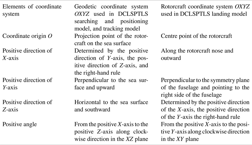
As shown in Figure 8, the rotorcraft coordinate system OXYZ is established with the centre point of the rotorcraft as the coordinate origin O, where the positive direction of the X-axis is along the rotorcraft nose and outward, the positive direction of the Y-axis is perpendicular to the symmetry plane of the fuselage and points to the right side of the fuselage, and the positive direction of the Z-axis is determined by the right-hand rule. In the XY plane, the angle from the positive X-axis to the positive Y-axis along the clockwise direction is positive. The length and width of the deck at the apron area respectively are ${L_d}$ and ${W_d}$
 , and the apron is at the centre of the deck. The direction of the DCLSPTLS lateral channel beam in the XY plane is consistent with the positive direction of the X-axis. The angle between the DCLSPTLS lateral channel beam and the vertical channel beam is ${\theta _D}$
 , the lateral channel rotates clockwise at the speed n, and the lateral channel laser emission frequency is ${f_{\textrm{side}}}$
 . The simulation time step is $\Delta t = 1/{f_{\textrm{side}}}$
 .
DCLSPTLS landing model diagram

When the DCLSPTLS lateral channel laser beam rotates once and illuminates the deck at the apron, the circle scanned by the laser beam is exactly tangent to the deck width. At this time, the height of the rotorcraft ${H_{r0}}$ is as follows:

When the distance obtained by the DCLSPTLS vertical channel is not larger than ${H_{r0}}$ , the DCLSPTLS lateral channel starts to rotate and detect. Assuming that the distances obtained by one rotation of the DCLSPTLS lateral channel laser beam are ${l_{sc}}({c = 0,1, \ldots ,1/({n\Delta t} )} )$
 , the coordinates of the laser irradiation point of the DCLSPTLS lateral channel including the change of the apron deck attitude, that is, the coordinates of the apron deck, are:

Assuming that the normal vector of the plane where the apron is located is $\mu = ({{K_1},{K_2},{K_3}} )$ , the plane where the apron is located can be expressed as follows:

Considering that the attitude of the deck changes slowly, the deck coordinates represented by Equation (21) are fitted by the least squares method. The sum of the squared residuals is as follows:

In order to find the minimum value of Equation (23), all deck coordinates involved in the calculation are expressed in a matrix as shown below.

By combining Equations (23) and (24), the equation can be obtained as follows:

where $b = {\left[ {\begin{array}{*{20}{c}} 1& 1& \ldots & 1 \end{array}} \right]^T}$ .
The angle at which the deck rotates around the Y-axis is the pitch angle $\theta$ , and the angle at which the deck rotates around the X-axis is the roll angle $\phi$
 . Then there is:

The rotorcraft adjusts its attitude in the opposite direction according to Equation (26) and descends to a certain height. The descending height value is approximately equal to the distance difference obtained by the DCLSPTLS vertical channel laser beam.
4. Simulation and measurement experiment
Many parameters are introduced in the proposed method. The optimal selection of these input parameters will determine the accuracy and robustness of the proposed method, as well as the effectiveness of the simulation and measurement experiment. The principles for selecting input parameters are determined as follows:
(a) The values of all input parameters are derived from actual requirements or within the range of performance indicators that can be achieved by related products. For example, the size value of a ship at sea is mainly determined by whether the ship has actual requirements for using the rotorcraft, whether it has an apron, and whether its size is large. Another example is the selection of the DCLSPTLS's repetition frequency based on the pulse repetition frequency in Table 1, the internal resources of the processor and the main frequency. The last example is the selection of the DCLSPTLS's detection distances to the ship and to the sea surface based on the parameters described in Equation (1) and the number of accumulated echo pulses in Table 3, such as the pulse power in Table 1, the near-IR band laser reflectivities of the deck and the sea surface, and the noise equivalent power.
(b) Some input parameters values need to take the maximum value, minimum value or typical value within the performance index range of relevant products, in order to reduce resource consumption and cover more applications. For example, the climbing or landing speed of the rotorcraft is the maximum value of its climbing or landing speed, and the rotorcraft tracking speed is the maximum value that can be used for level flight, all in order to achieve the purposes that the rotorcraft can complete the searching and positioning of the ship as soon as possible and thereby save power. For another example, the variation range and rate of pitch angle and roll angle of the apron are the variation range and rate of pitch angle and roll angle of marine ships that can withstand severe sea conditions, so as to ensure that the proposed algorithm can cover more application scenarios. For the last example, the rotational speed of the DCLSPTLS is a typical rotation speed so that the stepper motor will not affect the flight of the rotorcraft when the torque of the stepper motor and the weight of the DCLSPTLS are constant.
In order to show the simulation results better, the coordinate systems in the above models are redescribed in Table 4 to make the contrast clearer.
Coordinate systems used in the models

4.1 DCLSPTLS searching and positioning model simulation
The relevant parameters are set as follows: ‘the ship’ refers to the Chinese scientific research ship Xuelong. The ship size is 167 m × 22 · 6 m × 13 · 5 m. The coordinates of the deck centre are (500, 13 · 5, 500) and the speed of the ship ${V_s}$ is 1 · 5m/s. The angle ${\theta _s}$
 between the speed and the positive direction of the X-axis is 330°, and the angle ${\theta _D}$
 between the DCLSPTLS lateral channel laser beam and the vertical channel laser beam is 25°. The detection distances ${L_{s\max }}$
 from each channel laser beam to the ship and to the sea surface are 2,000 m and 37 m respectively, and the initial coordinates of the rotorcraft are (0, 1812, 0). The climbing or landing speed ${V_r}$
 of the rotorcraft is 5 m/s, and the rotational speed n of DCLSPTLS is 2r/s, the pulse repetition frequency ${f_{side}}$
 of the lateral channel laser is 10 kHz, and the simulation time step $\Delta t$
 is 100 μs.
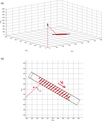
Figure 9 shows the simulation result of the DCLSPTLS searching and positioning model, and Figure 9(a) and 9(b) are the stereogram and the local graph, respectively. The red line is the laser beam irradiated by the DCLSPTLS and the red points are the scanning trajectory of the DCLSPTLS lateral laser beam on the ship, the black rectangle is the ship when the search is stopped, and the blue points are the flight path of the rotorcraft. It can be seen from Figure 9 that the DCLSPTLS searching and positioning model is effective and the ship can be scanned as expected. Some of the red points in Figure 9(b) are outside the ship, which is caused by the movement of the ship. The red points in Figure 9(b) form several straight lines, and the azimuths of the DCLSPTLS lateral laser beam represented by the points on each straight line are the same and the phase difference of two adjacent points on each straight line is 2π. Since the scan diameter is too large and the proportion of the arc is too small, the black dotted line indicates the scanning trend of the DCLSPTLS lateral laser beam.
Simulation result of DCLSPTLS searching and positioning model: (a) stereogram of simulation result, (b) local graph of simulation result

Figure 9 shows that the DCLSPTLS can accurately obtain the distance and azimuth of the ship relative to the rotorcraft. The laser beam is simplified into a line shape in the model and the rotational speed of the rotational component of the DCLSPTLS is assumed to be constant. The theoretical accuracy of the distance and azimuth of the ship relative to the rotorcraft is very high. The accuracy is determined by the ranging accuracy and the rotation accuracy of the DCLSPTLS lateral laser beam.
In order to test the accuracy of the ship speed direction ${\theta _s}$ measured by the midpoint connection method, a simulation is performed with ${\theta _s}$
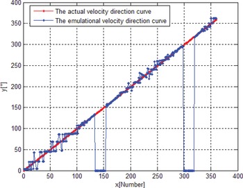
 set with an order of 1° step in [0°, 359°] and the remaining parameters are unchanged. The simulation results are shown in Figure 10. The measured ship speed direction is 0° when the value of ${\theta _s}$
 is in the range of [133°, 152°] and [298°, 317°] in Figure 10, because the relative positions of the ship and the rotorcraft are the same as the situation in Figure 5(b) and the scanning arc length of the DCLSPTLS lateral laser beam is close to the ship's length. The measured speed direction is represented by zero because it cannot be calculated. It can be seen from Figure 10 that the error of the measured speed direction is small and is no more than 15°, and the influence of the error can be significantly reduced to estimate the tracking trajectory by considering the error and the shape size.
Simulation velocity direction curve

It should be noted that the simulation parameters of the searching and positioning model are set based on the real parameters of the ship and the DCLSPTLS. Since the angle between the two channels of the DCLSPTLS and the climbing/landing speed of the rotorcraft cannot exceed 25° and 5 m/s respectively, the speed of the ship can be no more than 2 m/s. Otherwise, the rotorcraft will not be able to search the target when the rotorcraft climbs, and it will cause the DCLSPTLS searching and positioning model to fail. In order to make the DCLSPTLS application range wider, the angle between the two channels of DCLSPTLS can be increased. But at the same time, the feasibility of manufacturing the DCLSPTLS and the reduction of detection distance caused by a large incident angle of laser detection should be balanced.
4.2 DCLSPTLS tracking model simulation
The relevant parameters at the end of the simulation of the DCLSPTLS searching and positioning model are used as simulation inputs for the DCLSPTLS tracking model. The relevant parameters are set as follows: The coordinates of the centre of the Xuelong's deck are (587 · 1, 13 · 5, 449 · 7), and the azimuth angle ${\theta _{r0}}$ of the ship relative to the rotorcraft estimated by DCLSPTLS is 43 · 3°. The ship speed ${V_s}$
 is 1 · 5m/s, and the angle ${\theta _s}$
 between the ship's course and the positive direction of the X-axis is 330°. The angle ${\hat{\theta }_s}$
 between the ship's course estimated by the DCLSPTLS and the positive direction of the X-axis is 332°. The distance ${L_c}$
 between the rotorcraft and the ship measured by the DCLSPTLS lateral channel laser beam is 1,659 · 3m, the angle ${\theta _D}$
 between the DCLSPTLS lateral channel laser beam and the vertical channel laser beam is 25°. The detection distances ${L_{s\max }}$
 of each channel laser beam to the ship and to the sea surface are 2,000 m and 37 m respectively. The initial coordinates of the rotorcraft are (0, 1517, 0) and the rotorcraft tracking speed ${V_r}$
 is 20 m/s. The angle ${\varphi _r}$
 between the direction of the tracking speed and the positive direction of the Y-axis is 95°. The typical speed of the ship ${\hat{V}_s}$
 is 7 m/s, and the simulation time step $\Delta t$
 is 1 s.
When the rotorcraft starts to track, the above simulation parameters are brought into Equations (18) and (19). The total tracking time T = 42 · 36s and the angle ${\theta _r} = {23\unicode{x2009}\unicode{x00B7}\unicode{x2009}9^ \circ }$ between the tracking speed and the positive direction of the X-axis are then calculated respectively. Finally, the rotorcraft tracks the ship at the maximum speed of the rotorcraft ${V_r}$
 = 20 m/s, and the maximum inclination ${\varphi _r}$
 = 95° and ${\theta _r}$
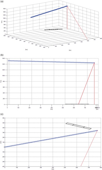
 = 23 · 9°. Figure 11 shows the simulation results of the DCLSPTLS tracking model: Figure 11(a) is the stereogram of the tracking result, Figure 11(b) is the side view of the tracking result, and Figure 11(c) is the top view of the tracking result. The blue points in Figure 11 are the tracking path of the rotorcraft, and the two red lines are the two channels laser beams of the DCLSPTLS. The two black rectangles are the ship: one is the ship at the beginning of the tracking and the other is the ship at the end of the tracking. It can be seen from Figure 11 that, at the end of the tracking, the position of the rotorcraft is not nearly above the ship, but above the front of the ship. They are 67 · 4 m apart in the horizontal plane.
Simulation result of DCLSPTLS tracking model: (a) tracking result stereogram, (b) tracking result side view, (c) tracking result top view

This is due to the fact that the typical driving speed of the ship used in calculating the tracking trajectory, 7 m/s, is far from the actual driving speed of 1 · 5 m/s. Since the estimated ship's course used in calculating the tracking trajectory is 332°, which is quite close to the actual driving speed direction of 330°, the rotorcraft hovers over the place where the ship is about to arrive. Because the DCLSPTLS has the ship's estimated course and the ship's speed does not exceed 7 m/s (the ship is a cooperation target), the rotorcraft can fly in the opposite direction of the ship's estimated course and it is inevitable that it will fly in the vicinity of the ship.
4.3 DCLSPTLS landing model simulation
The relevant parameters are set as follows: the size of the ship apron is 20 m × 20 m and the height of the apron is 21 · 4 m. The coordinates of the apron centre are (0, 0, 21 · 4). The pitch angle $\theta$ of the apron and the roll angle $\varphi$
 of the apron are linearly changed from −45° to 45° in 6 s. The angle ${\theta _D}$
 between the DCLSPTLS lateral channel laser beam and the vertical channel laser beam is 25°. The DCLSPTLS rotational speed n is 2 r/s, the pulse repetition frequency ${f_{\textrm{side}}}$
 of the lateral channel laser is 10 kHz, the simulation time step $\Delta t$
 is 100 μs and the total simulation time is 6 s. The rotorcraft hovers at (0, 0, 0), and only the DCLSPTLS performs a rotating motion. The estimated pitch angle $\hat{\theta }$
 and the estimated roll angle $\hat{\varphi }$
 of the apron are obtained by the simulation to evaluate the accuracy of the DCLSPTLS landing model.
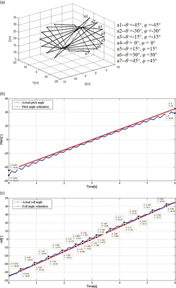
Figure 12 shows the simulation results of the DCLSPTLS landing model, where Figure 12(a) shows the apron positions corresponding to the apron attitudes, Figure 12(b) is the pitch angle comparison of the apron, and Figure 12(c) is the roll angle comparison of the apron. There are seven rectangles in Figure 12(a) indicating the apron positions corresponding to the apron attitudes at intervals of 1 s in a range of 0 s–6 s, and it is only to prove that the pitch angle and roll angle of the apron are variable. The red curves in Figure 12(b) and (c) are the actual pitch angle curve and the actual roll angle, which vary linearly with time from –45° to 45° in the simulation. The blue curves in Figure 12(b) and (c) are obtained by calculating and estimating the pitch angle and the roll angle of the apron for every 50 coordinates of irradiation points on the apron accumulated by the DCLSPTLS. It can be seen from Figure 12 that the maximum error of the estimated pitch angle is –7 · 23° when the actual pitch angle is –44 · 92°, and the maximum error of the estimated roll angle is –2 · 776° when the actual roll angle is 9 · 904°.
Simulation results of DCLSPTLS landing model: (a) apron position corresponding to the apron attitude, (b) pitch angle comparison of the apron, (c) roll angle comparison of the apron

4.4 Test of DCLSPTLS
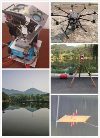
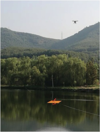
The test of the DCLSPTLS was designed to verify the performance of the DCLSPTLS such as the ability to identify the ship and the sea surface, and the ranging and angle measurement accuracy. As shown in Figure 13, the test system is a DCLSPTLS prototype, a rotorcraft, a data link, a total station, a model ship (in the lower right corner of Figure 13, which is equivalent to a reduced-scale ship deck), a lake, a type of portable computer and many different types of batteries. The test parameters of DCLSPTLS are shown in Table 5.
Test conditions and equipment

Test parameters of DCLSPTLS

The fixed height measurement test of the rotorcraft was designed as follows. The manually remote-controlled rotorcraft flies to hover nearly above the reduced-scale ship. The DCLSPTLS works and records the laser echo information, ranging information of the DCLSPTLS lateral channel and vertical channel, and the angle information by the pulse encoder. During the test, the DCLSPTLS reduced its gain and its rotation speed to 0 · 5 r/s to adapt to the close detection. Figure 14 shows how the rotorcraft carries the DCLSPTLS for the test on a reduced-scale ship.
Experimental picture from DCLSPTLS

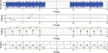
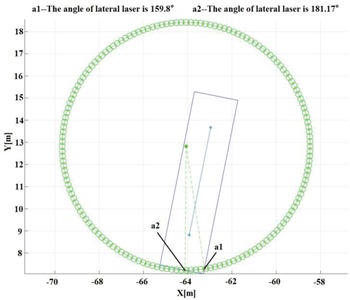
Figure 15 shows the results of the fixed height measurement test of the rotorcraft. The curves from top to bottom are as follows: DCLSPTLS lateral channel laser echo (Echo), DCLSPTLS vertical channel laser ranging curve (DisA), DCLSPTLS lateral channel laser ranging curve (DisB) and DCLSPTLS rotation angle measurement curve (Angle). The initial angle of DCLSPTLS is towards the bow along the long axis of the ship, and it rotates clockwise (when viewed from above). Figure 16 shows the relative positions and azimuths of the rotorcraft and the reduced-scale ship measured by the total station.
Experiment results of the fixed height test

Total station results of the fixed height test

It can be seen from Figure 15 and Figure 16 that:
(a) When the rotorcraft is tested at the actual measuring position, the DCLSPTLS vertical channel laser beam is vertically incident on the surface of the ship.
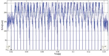
(b) The laser echo curve in Figure 15 consists of two curves, which means that it has been performed twice during the test, and the time interval is about 6 s. According to the details of the laser echo in Figure 17, when the DCLSPTLS lateral channel laser illuminates the reduced-scale ship at 25° incident angle, a single laser pulse echo is saturated, which means that the reduced-scale ship can be detected at 12 m height without pulse accumulation. The duration of the DCLSPTLS lateral channel laser irradiation on the reduced-scale ship is about 116 ms every rotation in Figure 17, and the corresponding angle difference is about 20 · 88°. The duration calculated by geometric relation in Figure 16 is about 119 ms, and the corresponding angle difference is about 21 · 37°. Considering the drift of the yaw angle of the rotorcraft, the measurement error with a duration 3 ms is acceptable, and the measurement test results are consistent with the theoretical calculation results.
(c) It can be seen from the DisA curve in Figure 15 that the height measured by the DCLSPTLS vertical channel laser to the reduced-scale ship is 11 m–13 m. The height measured by the total station is 12 m, and the maximum error is 1 m.
It should be noted that the two-channel laser outputs a ranging value every 64 ms because the laser pulse repetition period is 4 ms and 16 pulse echoes need to be accumulated. Considering the 80 MHz sampling clock, the 1 m maximum error is acceptable. For close-range ranging, the signal output from the comparison circuit in the DCLSPTLS can be used for ranging. By debugging a reasonable threshold, the DCLSPTLS close-range ranging error can be no more than 0 · 5 m.
(a) The curve DisB in Figure 15 shows that the lateral channel laser detects the reduced-scale ship with a 2 s period. The rotation period of the stepper motor is set to 2 s. Thus, the actual measurement period is consistent with the theoretical period. The distance to the reduced-scale ship measured by the DCLSPTLS lateral channel laser is 13 m–15 m while the theoretical distance is 13 · 5 m. The maximum distance error is 1 · 5 m which is acceptable. When the DCLSPTLS lateral channel laser irradiates the lake surface, no ranging value is obtained. It is displayed as 0 m in the curve. When the DCLSPTLS lateral channel laser irradiates the ship, the corresponding azimuth is 152 · 3°–170 · 7° by comparing the special points coordinates of the DisB curve and the Angle curve in Figure 15, while the azimuth calculated theoretically in Figure 16 is 159 · 8°. Considering the drift of the yaw angle of the rotorcraft in the measured process, these errors are acceptable.
Laser echo detail of the fixed height test

5. Conclusion and future perspectives
This paper describes the modelling, simulation and test of a dual-channel LIDAR searching, positioning, tracking and landing system for rotorcraft in relation to ships at sea. The azimuth angle and the distance of the ship relative to the rotorcraft, the ship's course, the total tracking time, the direction of the rotorcraft tracking speed, and the pitch and the roll angle of the ship's deck relative to the rotorcraft can be accurately calculated by using the ranging information of the two-channel LIDAR and the angle of the pulse encoder of the stepper motor. The simulation results show that DCLSPTLS has the advantages of high accuracy of motion estimation, wide range, and high reliability in distinguishing the ship's deck from the sea surface. The test results further verify the effectiveness of the DCLSPTLS.
However, there is still room to improve the performance and ability of rotorcraft to search, locate, track and land on a ship at sea. For example, the position of a ship could be predicted using the ship's behaviour from AIS records such as latitude, longitude, speed and course (Liu et al., Reference Liu, Guo, Nie, Hu, Xiong, Yu and Guizani2022). The DCLSPTLS cannot determine the speed value of the ship during the searching and positioning stage and cannot obtain information about the ship during the tracking stage. Thus, the DCLSPTLS can gain the ship information by using the AIS data during those stages, and the fusion of the AIS data and the DCLSPTLS data could also be studied by a deep lightweight neural network or a fuzzy logic fusion algorithm. Furthermore, laser point cloud data could also be used by the DCLSPTLS to obtain more information about the ship, such as visual information. The above improvements would all involve the improvement of the DCLSPTLS's signal processor. To achieve a balance between the fusion algorithm of the multi-sensor data and the DCLSPTLS signal processor, there is still a lot of work to be done in the future.
Acknowledgements
This work has been supported by China Postdoctoral Science Foundation (2018M630059).