1. Introduction
The creative design of mechanisms is widely regarded as one of the most important branches of the theory of mechanisms [Reference Yang, Ding and Kecskeméthy1]. As a new type of mechanism, parallel driving mechanism (PDM) [Reference Shi, Zhang, Wang, Li and Huang2] represents a subset of hybrid manipulator [Reference Li, Ye, Shen, Wang and Geng3–Reference Gupta, Gupta and Ekta5]. By definition, the PDM consists of an operating mechanism, multiple driving mechanisms, and connecting joints. Based on this, this paper proposed a 2T2R PDM. The 2T2R manipulator organically combines spatial translation and rotation, and is widely used in industry. For example, this manipulator can be combined with linear guide rail to form a five-axis linkage CNC machine tool [Reference Zhou, Li, Li, Meng, Li and Xu6, Reference Tang and Zhang7] and can also be used as motion simulator [Reference Wei, Fang and Liu8], vibration isolation platform [Reference Lu, Wu, Ding and Chen9], and so on. Among which, CNC machine tools have requirements for high accuracy of the manipulator, while the others have certain requirements for high-frequency and high-acceleration characteristics. In general, the PDM involves more sub-closed loops [Reference To and Webb10, Reference Nguyen, Zhou, Kang and Le11] and over-constraints [Reference Chen, Zhang, Qin and Sun12, Reference Xu, Liu, Yao and Zhao13]. Excluding actuators, its operating mechanism is independent of the driving mechanism, which makes the mechanism perform well in terms of structural stiffness [Reference Zhao, Gao, Li, Liu and Zhao14, Reference Wu, Li, Wang and Wang15] and high acceleration [Reference Shan, Li, Liu and Huang16, Reference Li-xin and Yong-gang17]. Similar to parallel mechanisms, the PDM has drawbacks such as small workspace, difficulty in solving forward kinematics, and complex control. In addition, there are new challenges in dynamic modeling due to over-constraints and the closed-loop structure.
In contrast to the open-chain serial manipulators, the dynamic analysis of parallel manipulators is inherently complex due to their closed-loop structure. Nevertheless, dynamic modeling plays an essential role in structural design and control scheme design for parallel manipulators. However, the requirements for dynamic models are different, which depends on the exact application. For the control scheme design, the dynamic model must be efficient enough for the real-time calculation; for the structural design, it is necessary to calculate the driving forces/torque and the constrained forces/moments simultaneously [Reference Chen, Xu, Zhang and Li18]. In general, dynamic modeling methods [Reference Chen, Wu, Deng and Wang19–Reference Tian, Flores and Lankarani21] can be divided into four categories: Lagrangian formula [Reference Flores, Ambrósio, Claro, Lankarani and Koshy22, Reference McGrath, Howard and Baker23], Newton–Euler method [Reference Chen, Xu, Zhang and Li18, Reference Marques, Roupa, Silva, Flores and Lankarani24, Reference Dasgupta and Mruthyunjaya25], virtual work principle [Reference Chen, Zhang, Qin and Sun26, Reference Zhao and Gao27], and Kane equation [Reference Pedrammehr, Nahavandi and Abdi28]. Among them, the Lagrangian formula is advantageous in solving the driving force of manipulator, with its explicit dynamic form conducive to dynamic analysis and control. Newton–Euler method can be used not only to solve the driving force but also to solve all the constraints/torques of joints effectively. However, the number of equations is generally smaller than the unknown number under the over-constrained mechanism, which makes it challenging to solve the dynamic model. At present, there have been some studies conducted on the dynamic modeling of the over-constrained parallel manipulators. Xu et al. [Reference Xu, Liu, Yao and Zhao29] proposed a new approach to the force analysis of over-constrained parallel mechanisms with lower mobility parallel mechanism, with consideration given to the spatial compound elastic deformation of the rod. Chen et al. [Reference Chen, Xu, Zhang and Li18] used the Newton–Euler formula and the natural orthogonal complement method to establish dynamic models with and without constraint force/moment simultaneously, with the deformation caused by over-constraint force/moment deduced. Bi et al. [Reference Bi and Kang30] constructed the dynamic model of the over-constrained mechanism Exechon by combining Newton–Euler formula with compliance conditions. The established dynamic model can be combined with the control system to improve the precision and dynamic performance of real-time control. For a mechanism subjected to the active and passive redundant constraints without parasitic motion, Chen et al. [Reference Chen, Yu, Li and Wang31] established an efficient dynamic model in line with the principle of virtual work by introducing classical optimization criteria and deformation coordination conditions. To sum up, the above-mentioned studies have contributed great ideas to solving the over-constrained mechanisms.
As can be seen from the above, introducing link flexibility is a common method for analyzing over-constrained mechanisms. The links’ elastic deformation can not only supplement the deformation coordination equation [Reference Elgolli, Houidi, Mlika and Romdhane32, Reference Yi, Li and Wang33] in the over-constrained direction but also cause pose error of the end-effector. The former provides a basis for the lightweight design. It focuses on using the links’ elastic deformation to solve the constraint force/moment [Reference Wang, Liu and Huang34] and joint friction [Reference Sharifzadeh, Arian, Salimi, Masouleh and Kalhor35] of the manipulator. As for the latter, it focuses on the impact of the rigid–flexible coupling [Reference Chen, Jiang and Wang36–Reference Xiao, Yan, Chen, Zhang and Jiang38] characteristics, large-range rigid body motion, and the elastic deformation of the rod, on the errors in position and orientation of the end-effector. However, the hybrid manipulator is free from large-range rigid body motion in the over-constrained direction, and the link flexibility conforms to the assumption of linear elasticity and small deformation. Therefore, it is proposed in this paper to supplement the deformation compatibility equation in the over-constrained direction by introducing the flexibility matrix and the superposition principle into the process of theoretical calculation. To facilitate simulation, the assumed mode method is used for the link flexibility in ABAQUS. Then, dynamic verification is carried out using the rigid–flexible coupling dynamic model of the co-simulation of ADAMS and ABAQUS.
To sum up, there have been some methods developed to solve the over-constraint issue. However, the PDM is still more challenging than the traditional parallel mechanism in terms of structural complexity and static indeterminate times. In addition, sub-closed loops are another characteristic of PDM, and the over-constrained mechanisms containing sub-closed loops [Reference To and Webb39, Reference Nguyen, Zhou, Kang and Le40] are usually coupled in a nonlinear manner, which makes it difficult to conduct kinematic and dynamic analysis of them [Reference Chen, Wu, Deng and Wang19, Reference Li and Staicu41, Reference Shao, Wang, Yang and Liu42]. At present, there are still few reports on the dynamic modeling of the PDMs. In this paper, with a new 4-DOF PDM as the research object, the over-constrained direction is first analyzed through the screw theory. Then, the flexibility matrix and superposition principle are introduced to supplement the deformation compatibility equation in the over-constrained direction. Finally, a complete dynamic model involving all active forces/moments and restraint forces/moments is constructed. This modeling method is also applicable to other over-constrained PDMs.
The remainder of this paper is organized as follows. In Section 2, the system conceptual design is described. Then, the kinematics modeling of the PDM is detailed in Section 3, where the positions, velocities, and accelerations of all bodies in the manipulator are determined. In Section 4, dynamics modeling is performed using the Newton–Euler method. Moreover, compatibility equations are introduced in Section 5 to solve the over-constraint forces/moments. Then, numerical simulations and experiments are conducted in Section 6. Lastly, the conclusions of this study are drawn in Section 7.
2. System conceptual design
2.1. Mechanism configuration design
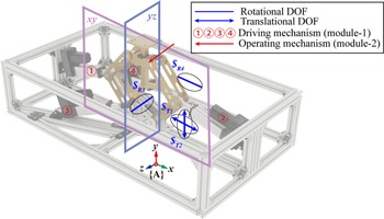
In this paper, a new 4-DOF PDM with two rotational DOFs and two translational DOFs is taken as the research object. The virtual prototype for the mechanism is represented in Fig. 1.
 $\boldsymbol{\$ }_{T1}$
and
 $\boldsymbol{\$ }_{T2}$
denote the translation along x-axis and y-axis, respectively.
 $\boldsymbol{\$ }_{R3}$
and
 $\boldsymbol{\$ }_{R4}$
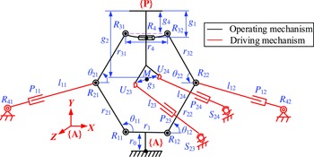
represent rotation around z-axis and x-axis, respectively. The 4-DOF PDM is composed of a fixed platform, a moving platform (MP), an operating mechanism and driving mechanisms. The driving mechanisms consist of four distributed limbs, with two identical RPR limbs and two identical SPU limbs. Each limb is formed by a cylinder and a piston and the prismatic joints of limbs are actuated, which are the inputs of the system, the position and orientation of the MP is the output. The operating mechanism consists of a six-bar mechanism and a revolute joint in series. As shown in Fig. 2,
 $R_{1i},R_{2i},R_{3i},R_{4i}$
, and
 $R_{4}(i=1,2)$
represent the revolute joint;
 $U_{2j}(j=3,4)$
represents the universal joint;
 $S_{2j}$
denotes the spherical joint;
 $P_{1i}$
and
 $P_{2j}$
represent the prismatic joint. The reference frame
P
-xyz and the moving frame
A
-xyz are attached to the MP and the base, respectively.
 $l_{1i}$
and
 $l_{2j}$
denote the location of the prismatic joint in each limb. The geometric parameters are given in Appendix A.
Virtual prototype for the 4-DOF PDM.

Joint type and number of the 4-DOF PDM.

Schematic diagram of the 4-DOF PDM.

2.2. Workspace analysis
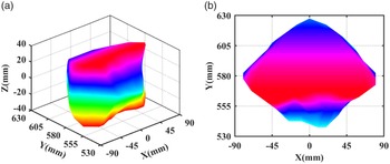
The boundary of the reachable workspace is determined with the help of boundary search method as shown in Fig. 3(a), where the z-axis is parasitic motion. Figure 3(b) shows its projection in the x–y direction. The link extensions,
 $l_{11},l_{12},l_{23}$
, and
 $l_{24}$
, are limited between −50 (mm) and 50 (mm) since the left and right grounded prismatic links are assumed to be physically constrained by the ground at those boundary angles. In addition, other link angles are also subject to certain constraints based on physical properties.
The reachable workspace of the 4-DOF PDM.

2.3. Over-constraint analysis
The PDM perform well in structural stiffness due to its closed-loop structure. Meanwhile, the closed-loop structure brings more over-constraints, which is necessary for the mobility and force analysis. Next, the over-constrained analysis of the 4-DOF PDM will be derived in detail. The joint type and number are shown in Table I.
The number of over-constraints on the 4-DOF PDM is calculated as follows:
 \begin{equation} t=3S+4U+5R+5P+A-6n=9 \end{equation}
3. Kinematic analysis
Kinematic analysis is an indispensable step in the evaluation and application. Therefore, position, velocity, and acceleration analysis of the 4-DOF PDM are presented in this section. In the following, the kinematics of the hybrid manipulator is solved in modules. As shown in Fig. 1, the module-1 represents the operating mechanism, and the module-2 denotes the driving mechanisms, including the 1st, 2nd RPR limbs and the 3rd, 4th SPU limbs. Meanwhile, the module-1 is solved prior to the module-2.
3.1. Inverse position analysis
3.1.1. Inverse position of module-1
Inverse position analysis determines the positions of each limb when the position and orientation of the MP are given. Any vector in the frame P -xyz can map to the frame A -xyz.
 \begin{equation} \boldsymbol{R} =\boldsymbol{T}\boldsymbol{R}'+\boldsymbol{P} \end{equation}
in which
 \begin{equation} \boldsymbol{T}=\boldsymbol{R}\!\left(z_{0},\alpha \right)\boldsymbol{R}\!\left(x_{0},\gamma \right) \end{equation}
 \begin{equation} \boldsymbol{P}=\left[\begin{array}{l@{\quad}l@{\quad}l} p_{x} & p_{y} & p_{z} \end{array}\right]^{T} \end{equation}
where T and P denote the orientation matrix and the position vector of the MP, respectively.
For the 1st and 2nd driving limbs, the position vector
 $R_{3i}(i=1,2)$
with respect to the frame
A
-xyz can be obtained based on the homogeneous transformation. In addition, the position vector
 $R_{2i}$
with respect to the frame
A
-xyz can be expressed by
 $\theta _{\mathrm{1}i}$
. We can derive the closed-loop motion equation as
 \begin{equation} \boldsymbol{R}_{1i}\boldsymbol{R}_{2i}=\boldsymbol{R}_{1i}\boldsymbol{R}_{3i}+\boldsymbol{R}_{3i}\boldsymbol{R}_{2i} \end{equation}
Eq. (5) can be simplified as follows
 \begin{equation} a_{1i}\cos \theta _{1i}+b_{1i}\sin \theta _{1i}=d_{1i} \end{equation}
in which
 \begin{equation} \theta _{1i}=a\tan 2\!\left(b_{1i},a_{1i}\right)\pm a\tan 2\left(\sqrt{a_{1i}^{2}+b_{1i}^{2}-d_{1i}^{2}},d_{1i}\right) \end{equation}
where atan2 stands for four-quadrant inverse tangent function.
 $a_{1i},b_{1i}$
, and
 $d_{1i}$
represent the simplified values of Eq. (5), and their expressions are detailed in Appendix B.
3.1.2. Inverse position of module-2
According to the constraint relationship, the length of
 $l_{1i}$
can be obtained
 \begin{equation} l_{1i}=\left\| \boldsymbol{R}_{2i}\boldsymbol{R}_{4i}\right\| \end{equation}
Similar to Eq. (8), the position vector of
 $U_{2j}(j=3,4)$
with respect to the frame
O
-xyz can be obtained. We can derive the length of
 $l_{2j}$
as
 \begin{equation} l_{2j}=\left\| \boldsymbol{U}_{2j}\boldsymbol{S}_{2j}\right\| \end{equation}
3.2. Velocity and acceleration analysis
The displacement of the prismatic joint is given by Eqs. (8) and (9). However, to derive the inverse dynamic formulation for the 4-DOF PDM with Newton–Euler method, the positions, velocities, and accelerations of all bodies in the hybrid manipulator are required to be derived. In the following, we will derive the inverse kinematics in detail.
3.2.1. Velocity and acceleration of module-1
The angular velocity, acceleration, and linear acceleration of the MP can be obtained
 \begin{equation} \boldsymbol{a}_{mp}=\boldsymbol{a}_{mp}^{\tau }+\boldsymbol{a}_{mp}^{n} \end{equation}
in which
 \begin{equation} \begin{array}{l} \boldsymbol{a}_{mp}^{\tau }=\boldsymbol{\varepsilon }_{mp}\times \boldsymbol{r}_{{R_{4}},P}\\ \boldsymbol{a}_{mp}^{n}=\boldsymbol{\omega }_{mp}\times \left(\boldsymbol{\omega }_{mp}\times \boldsymbol{r}_{{R_{4}},P}\right) \end{array} \end{equation}
where
 $\boldsymbol{\omega }_{mp}$
and
 $\boldsymbol{\varepsilon }_{mp}$
represent the angular velocity and acceleration of the MP, respectively.
 $\boldsymbol{a}_{mp}^{n}$
and
 $\boldsymbol{a}_{mp}^{\tau }$
denote the normal and tangential acceleration of the MP, respectively.
For the operating mechanism,
 $\theta _{2i}$
can be written as follows:
 \begin{equation} \theta _{2i}=a\text{cos}\!\left(P_{{R_{3i}}}-P_{{R_{2i}}}\right)/r_{3i} \end{equation}
Furthermore, differentiating Eq. (12) with respect to time yields
 \begin{equation} \begin{array}{l} \dot{\theta }_{2i}=\left(v_{{R_{2i}}}-v_{{R_{3i}}}\right)/\left(r_{3i}s\theta _{2i}\right)\\[6pt] \ddot{\theta }_{2i}=\left(a_{{R_{2i}}}-a_{{R_{3i}}}-r_{3i}c\theta _{2i}\dot{\theta }_{2i}^{2}\right)/\left(r_{3i}s\theta _{2i}\right) \end{array} \end{equation}
Since the operating mechanism is a planar mechanism, the angular velocity and acceleration of
 $l_{3i}$
can be written as follows:
 \begin{equation} \begin{array}{l} \boldsymbol{\omega }_{r3i}=\left[\begin{array}{l@{\quad}l@{\quad}l} 0 & 0 & \dot{\theta }_{2i} \end{array}\right]^{T}\\[6pt] \boldsymbol{\varepsilon }_{r3i}=\left[\begin{array}{l@{\quad}l@{\quad}l} 0 & 0 & \ddot{\theta }_{2i} \end{array}\right]^{T} \end{array} \end{equation}
Similarly, the acceleration of the operating mechanism can be written as
 \begin{equation} \boldsymbol{a}_{r3i}=\boldsymbol{a}_{r3i}^{\tau }+\boldsymbol{a}_{r3i}^{n}+\boldsymbol{a}_{{R_{2i}}} \end{equation}
in which
 \begin{equation} \begin{array}{l} \boldsymbol{a}_{r3i}^{\tau }=\boldsymbol{\omega }_{r3i}\times \boldsymbol{r}_{3i}\\ \boldsymbol{a}_{r3i}^{n}=\boldsymbol{\omega }_{r3i}\times \left(\boldsymbol{\omega }_{r3i}\times \boldsymbol{r}_{3i}\right)\\ \boldsymbol{a}_{{R_{2i}}}=\boldsymbol{a}_{R_{2i}}^{\tau }+\boldsymbol{a}_{R_{2i}}^{n} \end{array} \end{equation}
3.2.2. Velocity and acceleration of module-2
The Euler angle of the 1st and 2nd driving limbs can be written as follows:
 \begin{equation} \alpha _{li}=a\tan 2\!\left(b_{li},a_{li}\right) \end{equation}
The angular velocity and angular acceleration of
 $l_{i}$
can be obtained by differentiating Eq. (17). Similar to Eq. (14), the angular velocity and acceleration vector can be expressed as
 \begin{equation} \begin{array}{ll} \boldsymbol{\omega }_{li} & =\left[\begin{array}{l@{\quad}l@{\quad}l} 0 & 0 & \omega _{li} \end{array}\right]^{T}\\[6pt] \ddot{\boldsymbol{\alpha }}_{li} & =\left[\begin{array}{l@{\quad}l@{\quad}l} 0 & 0 & \ddot{\alpha }_{li} \end{array}\right]^{T} \end{array} \end{equation}
Furthermore, the acceleration at the center of mass of the cylinder can be written as follows:
 \begin{equation} \boldsymbol{a}_{li1}\boldsymbol{=}\boldsymbol{a}_{li1}^{t}+\boldsymbol{a}_{li1}^{n} \end{equation}
in which
 \begin{equation} \begin{array}{l} \boldsymbol{a}_{li1}^{t}=\boldsymbol{\alpha }_{li}\times \boldsymbol{r}_{i1}\\ \boldsymbol{a}_{li1}^{n}=\boldsymbol{\omega }_{li}\times \left(\boldsymbol{\omega }_{li}\times \boldsymbol{r}_{i1}\right) \end{array} \end{equation}
Similarly, the acceleration at the center of mass of the piston can be written as
 \begin{equation} \boldsymbol{a}_{li2}=\boldsymbol{a}_{li2}^{\tau }+\boldsymbol{a}_{li2}^{n}+\boldsymbol{a}_{li2}^{k} \end{equation}
in which
 \begin{equation} \begin{array}{l} \boldsymbol{a}_{li2}^{\tau }=\boldsymbol{\alpha }_{li}\times \boldsymbol{r}_{i2}\\ \boldsymbol{a}_{li2}^{n}=\boldsymbol{\omega }_{li}\times \left(\boldsymbol{\omega }_{li}\times \boldsymbol{r}_{i2}\right)\\ \boldsymbol{a}_{li2}^{k}=2\boldsymbol{\omega }_{li}\times \boldsymbol{v}_{r} \end{array} \end{equation}
where
 $\boldsymbol{a}_{li2}^{k}$
denote the Coriolis acceleration of the piston in 1st and 2nd driving limbs.
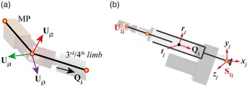
For the U joint in the 3rd and 4th driving limbs, many papers assume that the angular velocity and acceleration are perpendicular to the direction along SPU limb for the convenience of derivation. In this paper, the actual angular velocity and acceleration values are obtained through geometric constraint relationship. The local coordinate frame attached to the U joint is shown in Fig. 4.
Coordinate frame of the U joint.

The coordinate systems of the 3rd and 4th driving limbs are shown in Fig. 4. First, we assume that the orientation matrix of the 3rd and 4th driving limbs frame
Q
-xyz with respect to the reference frame
A
-xyz can be derived in terms of three rotational angles
 $\alpha,\beta$
, and
 $\gamma$
satisfying the z-x-z convention:
 \begin{equation} \begin{array}{l} \boldsymbol{R}_{z}\!\left(\alpha \right)\boldsymbol{R}_{x}\!\left(\beta \right)\boldsymbol{R}_{z}\!\left(\gamma \right)\\ =\left[\begin{array}{c@{\quad}c@{\quad}c} \mathrm{c}\alpha \mathrm{c}\gamma -\mathrm{s}\alpha \mathrm{c}\beta \mathrm{s}\gamma & -\mathrm{c}\alpha \mathrm{s}\gamma -\mathrm{s}\alpha \mathrm{c}\beta \mathrm{c}\gamma & \mathrm{s}\alpha \mathrm{s}\beta \\ \mathrm{s}\alpha \mathrm{c}\gamma +\mathrm{c}\alpha \mathrm{c}\beta \mathrm{s}\gamma & -\mathrm{s}\alpha \mathrm{s}\gamma +\mathrm{c}\alpha \mathrm{c}\beta \mathrm{c}\gamma & -\mathrm{c}\alpha \mathrm{s}\beta \\ \mathrm{s}\beta \mathrm{s}\gamma & \mathrm{s}\beta \mathrm{c}\gamma & \mathrm{c}\beta \end{array}\right] \end{array} \end{equation}
where s and c represent the abbreviations of sine and cosine, respectively. In addition,
 $\boldsymbol{Q}_{j}$
can be obtained by the following equation:
 \begin{equation} \boldsymbol{Q}_{j}=\frac{\boldsymbol{U}_{2j}\boldsymbol{S}_{2j}}{\left\| \boldsymbol{U}_{2j}\boldsymbol{S}_{2j}\right\| } \end{equation}
Hence, taking Eqs. (23) and (24) into account, the Euler angle of
 $l_{2j}$
can be written as follows:
 \begin{equation} \begin{array}{l} \alpha =-a\tan 2\!\left(\boldsymbol{Q}_{j}\left(1,1\right),\boldsymbol{Q}_{j}\left(2,1\right)\right)\\ \beta =a\cos\! \left(\boldsymbol{Q}_{j}\left(3,1\right)\right) \end{array} \end{equation}
Differentiating Eq. (25) with respect to time,
 $\dot{\alpha }, \ddot{\alpha }, \dot{\beta }$
, and
 $\ddot{\beta }$
can be obtained, respectively. To derive the Euler angle
 $\gamma$
, it is necessary to supplement equations based on the geometric constraint relationship. Hence, we can derive
 $\boldsymbol{U}_{j2}$
as
 \begin{equation} \begin{array}{l} \boldsymbol{U}_{j2}\boldsymbol{=}\boldsymbol{Q}_{j}\times \boldsymbol{U}_{j1}\\[6pt] \boldsymbol{U}_{j2}^{e}=\frac{\boldsymbol{U}_{j2}}{\left| \boldsymbol{U}_{j2}\right| } \end{array} \end{equation}
where vector
 $\boldsymbol{U}_{j1}$
denotes the axis along with the MP at the U joint, vector
 $\boldsymbol{U}_{j2}$
denotes the axis along with the 3rd and 4th SPU limb. From Eqs. (23) to (26),
 $\gamma$
can be expressed as
 \begin{equation} \gamma =a\cos\! \left(\boldsymbol{U}_{j2}^{e}\left(3,1\right)\right)/\sin\! \left(\beta \right) \end{equation}
Differentiating Eq. (27) with respect to time,
 $\dot{\gamma }, \ddot{\gamma }$
can be obtained, respectively. In addition,
 $\boldsymbol{U}_{j3}$
can be obtained by vector cross product, which is the direction of the constrained torque at the U joint.
 \begin{equation} \boldsymbol{U}_{j3}=\boldsymbol{U}_{j1}\times \boldsymbol{U}_{j2} \end{equation}
Furthermore, to obtain the angular velocity of each link, we need to map the Euler angles rate to the angular velocity. The mapping principle is shown in Fig. 5.
Mapping of Euler angles rate to angular velocity.

According to the above transformation, Eq. (29) can be obtained
 \begin{equation} \left[\begin{array}{l} \omega _{x}\\ \omega _{y}\\ \omega _{z} \end{array}\right]=rot\!\left(z,\alpha \right)rot\!\left(x,\beta \right)\left[\begin{array}{l} 0\\ 0\\ \dot{\gamma } \end{array}\right]+rot\!\left(z,\alpha \right)\left[\begin{array}{l} \dot{\beta }\\ 0\\ 0 \end{array}\right]+\left[\begin{array}{l} 0\\ 0\\ \dot{\alpha } \end{array}\right] \end{equation}
By sorting out Eq. (29), the following equation can be obtained
 \begin{equation} \boldsymbol{\omega }_{lj}=\boldsymbol{J}_{t}\!\left[\begin{array}{l@{\quad}l@{\quad}l} \dot{\alpha }_{lj} & \dot{\beta }_{lj} & \dot{\gamma }_{lj} \end{array}\right]^{T} \end{equation}
in which
 \begin{equation} \boldsymbol{J}_{t}=\left[\begin{array}{c@{\quad}c@{\quad}c} 0 & c\alpha _{lj} & s\alpha _{lj}s\beta _{lj}\\ 0 & s\alpha _{lj} & -c\alpha _{lj}s\beta _{lj}\\ 1 & 0 & c\beta _{lj} \end{array}\right] \end{equation}
Furthermore, differentiating Eq. (30) with respect to time, the following equation can be obtained
 \begin{equation} \boldsymbol{\varepsilon }_{lj}=\boldsymbol{J}_{t}\!\left[\begin{array}{l@{\quad}l@{\quad}l} \ddot{\alpha }_{lj} & \ddot{\beta }_{lj} & \ddot{\gamma }_{lj} \end{array}\right]^{T}+\dot{\boldsymbol{J}}_{t}\!\left[\begin{array}{l@{\quad}l@{\quad}l} \dot{\alpha }_{lj} & \dot{\beta }_{lj} & \dot{\gamma }_{lj} \end{array}\right]^{T} \end{equation}
For the 1st and 2nd driving limbs,
L
1i
represents the vector between the two joints
 $R_{2i}$
and
 $R_{4i}$
 \begin{equation} \boldsymbol{L}_{1i}=\boldsymbol{r}_{2i}-\boldsymbol{r}_{4i} \end{equation}
where
 $\boldsymbol{r}_{2i}$
and
 $\boldsymbol{r}_{4i}$
represent the vectors of joint
 $R_{2i}$
and
 $R_{4i}$
with respect to frame {
A
}, respectively. Moreover, use
Q
1i
to denote the unit vector along
L
1i
 \begin{equation} \boldsymbol{Q}_{i}=\boldsymbol{L}_{1i}/l_{1i} \end{equation}
The velocity of any point in the moving frame can be obtained by vector cross-product
 \begin{equation} \boldsymbol{V}=\boldsymbol{V}'+\boldsymbol{\omega }\times \boldsymbol{r} \end{equation}
where
 $\boldsymbol{\omega }$
and
V
represent the angular velocity and the linear velocity of the MP, respectively.
Differentiating Eq. (7) with respect to time yields:
 \begin{equation} \dot{\theta }_{1i}=\boldsymbol{J}_{0i}\dot{\boldsymbol{P}} \end{equation}
where
 $\dot{\boldsymbol{P}}$
denotes the velocity matrix of the MP.
Similarly, linear velocity of l i by differentiating Eq. (8) can be obtained
 \begin{equation} \dot{l}_{1i}=\boldsymbol{J}_{1i}\dot{\boldsymbol{P}} \end{equation}
The linear acceleration of the MP can be obtained by the following formula
 \begin{equation} \boldsymbol{A}=\boldsymbol{A}'+\boldsymbol{\varepsilon }\times \boldsymbol{r}+\boldsymbol{\omega }\times \left(\boldsymbol{\omega }\times \boldsymbol{r}\right) \end{equation}
where
 $\boldsymbol{\varepsilon }$
denotes the angular acceleration of the MP.
Furthermore, differentiating Eq. (36) with respect to time yields:
 \begin{equation} \ddot{\theta }_{1i}=\boldsymbol{J}_{0i}\ddot{\boldsymbol{P}}+\dot{\boldsymbol{P}}^{T}\boldsymbol{H}_{0i}\dot{\boldsymbol{P}} \end{equation}
where
 $\ddot{\boldsymbol{P}}$
denotes the acceleration matrix of the MP.
Forces and moments analysis for the link-2.

Similarly, linear acceleration of
 $l_{i}$
can be obtained as time derivative of Eq. (37)
 \begin{equation} \ddot{l}_{1i}=\boldsymbol{J}_{1i}\ddot{\boldsymbol{P}}+\dot{\boldsymbol{P}}^{T}\boldsymbol{H}_{1i}\dot{\boldsymbol{P}} \end{equation}
For the 3rd and 4th driving limbs, the linear velocity can be calculated by Eq. (35)
 \begin{equation} \boldsymbol{V}_{U2j}=\boldsymbol{G}_{p}^{U_{2j}}\dot{\boldsymbol{P}} \end{equation}
 \begin{equation} l_{2j}^{2}=\boldsymbol{L}_{2j}\cdot \boldsymbol{L}_{2j} \end{equation}
Differentiating Eq. (42) with respect to time, the following formula can be obtained
 \begin{equation} l_{2j}\dot{l}_{2j}=\boldsymbol{L}_{2j}\cdot \boldsymbol{V}_{2j} \end{equation}
Hence, the velocity of the
 $l_{2j}$
can be expressed as follows:
 \begin{equation} \dot{l}_{2j}=\boldsymbol{Q}_{j}^{T}\boldsymbol{V}_{{U_{2j}}}=\boldsymbol{J}_{1j}\dot{\boldsymbol{P}} \end{equation}
in which
 \begin{equation} \boldsymbol{J}_{1j}=\boldsymbol{Q}_{j}^{T}\boldsymbol{G}_{p}^{U_{2j}} \end{equation}
According to the Eq. (38), the following formula can be obtained
 \begin{equation} \boldsymbol{A}_{{U_{2j}}}=\boldsymbol{G}_{p}^{U_{2j}}\ddot{\boldsymbol{P}}+\dot{\boldsymbol{P}}^{T}\boldsymbol{H}_{0j}\dot{\boldsymbol{P}} \end{equation}
Furthermore, linear acceleration of
 $l_{2j}$
can be obtained by differentiating Eq. (44)
 \begin{equation} \ddot{l}_{2j}=\boldsymbol{Q}_{j}^{T}\boldsymbol{A}_{{U_{2j}}}+\left(\boldsymbol{V}_{U_{2j}}^{T}\boldsymbol{V}_{{U_{2j}}}-\dot{l}_{2j}^{2}\right)/l_{2j} \end{equation}
Hence, the acceleration of the
 $l_{2j}$
can be written as follows:
 \begin{equation} \ddot{l}_{2j}=\boldsymbol{J}_{2j}\ddot{\boldsymbol{P}}+\dot{\boldsymbol{P}}^{T}\boldsymbol{H}_{1j}\dot{\boldsymbol{P}} \end{equation}
So far, all the kinematic parameters required for the inverse dynamics are determined. In the next section, attention will be paid on the deduction of dynamic equations of the 4-DOF PDM.
4. Dynamic analysis
For the structural design, the driving forces and the constrained forces/moments should be calculated simultaneously to evaluate the force condition of the system. Therefore, this section presents the dynamics modeling of the 4-DOF PDM. First, the force analysis of individual bodies, limbs are derived with Newton–Euler method. Then, based on the flexibility matrix and compatible deformation are employed to supplementary equations. Similar to the kinematic analysis, the dynamic derivation of the 4-DOF PDM is also solved in modules.
4.1. Forces and moments analysis for the module-1
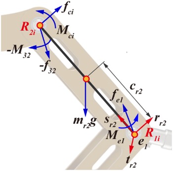
The forces and moments analysis diagrams of link
 $r_{21}$
are given in Fig. 6. The reaction forces and moments at fixed points
 $R_{1i}$
are denoted by
 $\boldsymbol{f}_{e1}$
and
 $\boldsymbol{M}_{e1}$
. The forces and moments at moving points
 $R_{2i}$
are denoted by
 $\boldsymbol{f}_{32}$
and
 $\boldsymbol{M}_{32}$
, respectively.
The Newton–Euler equations for link
 $r_{21}$
are given as
 \begin{align} \sum \boldsymbol{F}_{ext}&=\boldsymbol{f}_{ci}-\boldsymbol{f}_{32}+\boldsymbol{f}_{e1}+m_{r2}\boldsymbol{g}=m_{r2}\boldsymbol{a}_{r2} \nonumber\\ \sum {}^{ci1}{\boldsymbol{n}}{_{ext}^{}}&={}^{A}{\boldsymbol{I}}{_{cr2}^{}}\dot{\boldsymbol{\omega }}_{r2}+\boldsymbol{\omega }_{r2}\times {}^{A}{\boldsymbol{I}}{_{cr2}^{}}\boldsymbol{\omega }_{r2}\nonumber\\ & \quad+ c_{r2}\!\left(-\boldsymbol{s}_{r2}\times \boldsymbol{f}_{e1}\right)+c_{r2}\!\left(\boldsymbol{s}_{r2}\times \boldsymbol{f}_{ci}\right)+c_{r2}\!\left(\boldsymbol{s}_{r2}\times -\boldsymbol{f}_{32}\right)+\boldsymbol{M}_{ci}-\boldsymbol{M}_{32}+\boldsymbol{M}_{e1} \end{align}
Similar to link
 $r_{21}$
, other links’ forces and moments of the operating mechanism can be obtained.
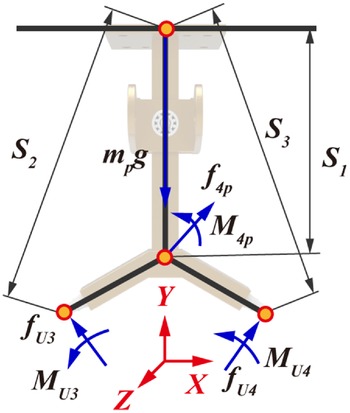
Furthermore, the forces and moments analysis for the MP are shown in Fig. 7.
Forces and moments analysis for the moving platform.

The Newton–Euler equations for MP are given as
 \begin{equation} \begin{array}{ll} \sum \boldsymbol{F}_{ext} & =\boldsymbol{f}_{4p}+\boldsymbol{f}_{U3}+\boldsymbol{f}_{U4}+m_{p}\boldsymbol{g}=m_{p}\boldsymbol{a}_{p}\\ \sum \boldsymbol{n}_{ext} & =\boldsymbol{S}_{1}\times \boldsymbol{f}_{4p}+\boldsymbol{S}_{2}\times \boldsymbol{f}_{U3}+\boldsymbol{S}_{3}\times \boldsymbol{f}_{U4}+\boldsymbol{M}_{U3}+\boldsymbol{M}_{U4}+\boldsymbol{M}_{4p}\\ & ={}^{A}{\boldsymbol{I}}{_{p}^{}}\dot{\boldsymbol{\omega }}_{p}+\boldsymbol{\omega }_{p}\times {}^{A}{\boldsymbol{I}}{_{p}^{}}\boldsymbol{\omega }_{p} \end{array} \end{equation}
4.2. Forces and moments analysis of the module-2
Assume that each driving limb consists of two parts, the cylinder and the piston, where the velocities and accelerations of their centers of masses are determined in Section 3. Assume that the centers of masses of the cylinder and the piston are located at a distance of
 $c_{i1}$
and
 $c_{i3}$
, and their masses are denoted by
 $m_{i1}$
and
 $m_{i2}$
, respectively. Moreover, consider that the cylinder and the pistons are symmetric about their axes, and their centers of masses lie at their midlengths.
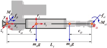
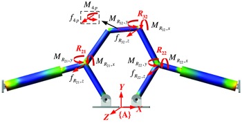
The forces and moments analysis diagrams of 1st and 2nd driving limb are given in Fig. 8. The reaction forces and moments at fixed points
 $R_{4i}$
are denoted by
 $\boldsymbol{f}_{fi}$
and
 $\boldsymbol{M}_{fi}$
. The forces and moments at moving points
 $R_{2i}$
are denoted by
 $\boldsymbol{f}_{ci}$
and
 $\boldsymbol{M}_{ci}$
, and the internal forces and moments between cylinders and pistons are denoted by
 $\boldsymbol{f}_{mi}$
and
 $\boldsymbol{M}_{mi}$
, respectively.
Forces and moments analysis for 1st and 2nd driving limbs.

The Newton–Euler equation for 1st and 2nd driving limbs are given as
 \begin{align} \left({}^{A}{\boldsymbol{I}}{_{ci_{1}}^{}}+{}^{A}{\boldsymbol{I}}{_{ci_{2}}^{}}\right)\dot{\boldsymbol{\omega }}_{i}+\boldsymbol{\omega }_{i}\times \left({}^{A}{\boldsymbol{I}}{_{ci_{1}}^{}}+{}^{A}{\boldsymbol{I}}{_{ci_{2}}^{}}\right)\boldsymbol{\omega }_{i}&=\boldsymbol{M}_{fi}+m_{i2}\!\left(L_{1}-c_{i3}\right)\left(\boldsymbol{s}_{i}\times \left(\boldsymbol{g}-\boldsymbol{a}_{i2}\right)\right)\nonumber\\ & \quad +m_{i1}c_{i1}\!\left(\boldsymbol{s}_{i}\times \left(\boldsymbol{g}-\boldsymbol{a}_{i1}\right)\right)+L_{1}\!\left(\boldsymbol{s}_{i}\times -\boldsymbol{f}_{ci}\right)-\boldsymbol{M}_{ci} \end{align}
where
 ${}^{A}{\boldsymbol{I}}{_{ci_{1}}^{}}$
denotes the inertia matrix of the cylinder evaluated at a frame parallel to {
A
} located at point
 $c_{i1}$
. Since the cylinder is moving with respect to this frame, this matrix can be evaluated by rotation rule from the inertia matrix easily obtained about {
A
i
} attached to the cylinder at point
 $c_{i1}$
. This can be done through the following transformation:
 \begin{equation} {}^{A}{\boldsymbol{I}}{_{ci_{1}}^{}}={}^{A}{\boldsymbol{R}}{_{Ai}^{}}\ {}^{A}{\boldsymbol{I}}{_{ci_{1}}^{}}\ {}^{A}{\boldsymbol{R}}{_{Ai}^{T}} \end{equation}
Note the formula of vector mixed product is as follows:
 \begin{equation} \left(\boldsymbol{a}\times \boldsymbol{b}\right)\cdot \boldsymbol{c}=\left(\boldsymbol{b}\times \boldsymbol{c}\right)\cdot \boldsymbol{a}=\left(\boldsymbol{c}\times \boldsymbol{a}\right)\cdot \boldsymbol{b} \end{equation}
Multiply
 $\boldsymbol{t}_{i}$
on both sides of Eq. (51), and the following equation can be obtained
 \begin{align} \boldsymbol{f}_\boldsymbol{ci}^{ri}&=m_{i1}c_{i1}\boldsymbol{r}_{i}\cdot \left(\boldsymbol{g}-\boldsymbol{a}_{i1}\right)+m_{i2}\!\left(L_{1}-c_{i3}\right)\boldsymbol{r}_{i}\cdot \left(\boldsymbol{g}-\boldsymbol{a}_{i2}\right)\nonumber\\ & \quad- \boldsymbol{t}_{i}\cdot \left(\left({}^{A}{\boldsymbol{I}}{_{ci1}^{}}+{}^{A}{\boldsymbol{I}}{_{ci2}^{}}\right)\dot{\boldsymbol{\omega }}_{i}\right)-\boldsymbol{t}_{i}\cdot \left(\boldsymbol{\omega }_{i}\times \left({}^{A}{\boldsymbol{I}}{_{ci1}^{}}+{}^{A}{\boldsymbol{I}}{_{ci2}^{}}\right)\boldsymbol{\omega }_{i}\right) \end{align}
Forces and moments analysis for piston are shown in Fig. 9.
Forces and moments analysis for the piston.

The Newton–Euler equations for piston are given as
 \begin{equation} \sum \boldsymbol{F}_{ext}=m_{i2}\boldsymbol{a}_{i2}=\boldsymbol{f}_{mi}-\boldsymbol{f}_{ci}+m_{i2}\boldsymbol{g} \end{equation}
By multiplying
 $\boldsymbol{s}_{i}$
on both sides of Eq. (55), formulas that only include driving force and kinematic parameters can be derived as follows:
 \begin{equation} f_{_{ci}}^{s}=\tau _{i}+m_{i2}\boldsymbol{g}\cdot \boldsymbol{s}_{i}-m_{i2}\boldsymbol{a}_{i2}\cdot \boldsymbol{s}_{i} \end{equation}
The forces and moments analysis diagrams of 3rd and 4th driving limbs are given in Fig. 10. The reaction forces and moments at fixed points
 $S_{2j}$
are denoted by
 $\boldsymbol{f}_{sj}$
and
 $\boldsymbol{M}_{sj}$
. The forces and moments at moving points
 $U_{2j}$
are denoted by
 $\boldsymbol{f}_{uj}$
and
 $\boldsymbol{M}_{uj}$
, and the internal forces and moments between cylinders and pistons are denoted by
 $\boldsymbol{f}_{mj}$
and
 $\boldsymbol{M}_{mj}$
, respectively.
Forces and moments analysis for 3rd and 4th driving limbs.

The Newton–Euler equation for 3rd and 4th driving limbs are given as
 \begin{align} \left({}^{A}{\boldsymbol{I}}{_{cj1}^{}}+{}^{A}{\boldsymbol{I}}{_{cj2}^{}}\right)\dot{\boldsymbol{\omega }}_{j}+\boldsymbol{\omega }_{j}\times \left({}^{A}{\boldsymbol{I}}{_{cj1}^{}}+{}^{A}{\boldsymbol{I}}{_{cj2}^{}}\right)\boldsymbol{\omega }_{j}&=-L_{j}\left(\boldsymbol{s}_{j}\times \boldsymbol{f}_{uj}\right)-m_{i2}\!\left(L_{j}-c_{i3}\right)\boldsymbol{s}_{j}\times \left(\boldsymbol{a}_{i2}-\boldsymbol{g}\right)\nonumber \\ & \quad-m_{i1}L_{31}\boldsymbol{s}\times \left(\boldsymbol{a}_{i1}-\boldsymbol{g}\right)-M_{uj}\boldsymbol{t}_{uj} \end{align}
According to Eq. (56), the following equation can be obtained
 \begin{equation} M_{uj}=\frac{\boldsymbol{s}_{j}\cdot \left(\left({}^{A}{\boldsymbol{I}}{_{ci1}^{}}+{}^{A}{\boldsymbol{I}}{_{ci2}^{}}\right)\dot{\boldsymbol{\omega }}_{j}\right)+\boldsymbol{s}_{j}\cdot \left(\boldsymbol{\omega }_{j}\times \left({}^{A}{\boldsymbol{I}}{_{ci1}^{}}+{}^{A}{\boldsymbol{I}}{_{ci2}^{}}\right)\boldsymbol{\omega }_{j}\right)}{-\boldsymbol{s}_{j}\cdot \boldsymbol{t}_{uj}} \end{equation}
Vector cross-product formula is as follows:
 \begin{equation} \boldsymbol{a}\times \left(\boldsymbol{b}\times \boldsymbol{c}\right)=\left(\boldsymbol{c}\cdot \boldsymbol{a}\right)\boldsymbol{b}-\left(\boldsymbol{a}\cdot \boldsymbol{b}\right)\boldsymbol{c} \end{equation}
Furthermore, by multiplying
 $\boldsymbol{s}$
on both sides of Eq. (57) and combing Eq. (59), the following equation can be obtained
 \begin{equation} \boldsymbol{f}_{uj}=\left(\boldsymbol{s}_{j}\cdot \boldsymbol{f}_{uj}\right)+\frac{1}{L_{j}}\boldsymbol{s}_{j}\times \left(\begin{array}{l} \left(m_{j2}\!\left(L_{j}-c_{j3}\right)\boldsymbol{s}_{j}\times \left(\boldsymbol{a}_{j2}-\boldsymbol{g}\right)\right)+\left(c_{j1}m_{j1}\boldsymbol{s}_{j}\times \left(\boldsymbol{a}_{j1}-\boldsymbol{g}\right)\right)\\[5pt] +\left(\left({}^{A}{\boldsymbol{I}}{_{cj1}^{}}+{}^{A}{\boldsymbol{I}}{_{cj2}^{}}\right)\dot{\boldsymbol{\omega }}_{j}\right)+\left(\boldsymbol{\omega }_{j}\times \left({}^{A}{\boldsymbol{I}}{_{cj1}^{}}+{}^{A}{\boldsymbol{I}}{_{cj2}^{}}\right)\boldsymbol{\omega }_{j}\right)+M_{uj}\boldsymbol{t}_{uj} \end{array}\right) \end{equation}
The forces and moments analysis of piston are shown in Fig. 11.
Forces and moments analysis for the piston.

The Newton–Euler equations for piston segments are given as
 \begin{equation} \boldsymbol{f}_{mj}-\boldsymbol{f}_{uj}+m_{j2}\boldsymbol{g}=m_{j2}\boldsymbol{a}_{j2} \end{equation}
Multiplying
 $\boldsymbol{s}$
on both sides of Eq. (61) and substituting Eq. (60) into Eq. (61), we have
 \begin{align} \boldsymbol{f}_{uj}&=\left(\tau _{j}+\boldsymbol{s}_{j}\cdot m_{j2}\boldsymbol{g}-\boldsymbol{s}_{j}\cdot m_{j2}\boldsymbol{a}_{j2}\right)\boldsymbol{s}_{j}\nonumber \\ &\quad +\frac{1}{L_{j}}\boldsymbol{s}_{j}\times \left(\begin{array}{l} \left(L_{j}-c_{j2}\right)\boldsymbol{s}_{j}\times m_{j2}\!\left(\boldsymbol{g}-\boldsymbol{a}_{j2}\right)+c_{j1}\boldsymbol{s}_{j}\times m_{j1}\!\left(\boldsymbol{g}-\boldsymbol{a}_{j1}\right)\\[5pt] +\left({}^{A}{\boldsymbol{I}}{_{cj1}^{}}+{}^{A}{\boldsymbol{I}}{_{cj2}^{}}\right)\dot{\boldsymbol{\omega }}_{j}+\boldsymbol{\omega }_{j}\times \left({}^{A}{\boldsymbol{I}}{_{cj1}^{}}+{}^{A}{\boldsymbol{I}}{_{cj2}^{}}\right)\boldsymbol{\omega }_{j}+M_{uj}\boldsymbol{t}_{uj} \end{array}\right) \end{align}
To sum up, there are 84 equations based on the Newton–Euler method, but 93 unknown variables need to be solved due to the over-constraints of the 4-DOF PDM. In the next section, nine compatibility equations are introduced considering the flexibility matrix and compatible deformation.
5. Deformation compatibility analysis
Based on the redundant constraint analysis in Section 2.2, we know that the 4-DOF PDM possesses nine passive redundant constraints, although the four actuator driving forces can be obtained with the classical method, the internal force analysis of this manipulator is still a statically indeterminate problem, and therefore the joint reaction forces cannot be uniquely determined. In this section, to obtain the unique solution, the over-constrained direction is analyzed by the screw theory, and the flexibility of the limbs is considered and the deformation compatibility condition is introduced.
5.1. Link’s elastic deformation
In this paper, the link is regarded as a homogeneous rod. As shown in Fig. 12, when the end link is subjected to external forces
 $\boldsymbol{F}\boldsymbol{=}[\begin{array}{cccccc} F_{x} & F_{y} & F_{z} & M_{x} & M_{y} & M_{z} \end{array}]^{T}$
, corresponding six-dimensional deformation will be formed, including tension, torsion, and bending.
Schematic diagram of deformation at the end of uniform bar with regular section.

The relation between the external force F and the corresponding small deflection X along the applied force axis can be written as follows
 \begin{equation} \boldsymbol{X}=\boldsymbol{CF} \end{equation}
in which
 \begin{equation} \boldsymbol{C}=\left[\begin{array}{cccccc} \dfrac{l}{EA} & 0 & 0 & 0 & 0 & 0\\ 0 & \dfrac{l^{3}}{3EI_{z}} & 0 & 0 & 0 & \dfrac{l^{2}}{2EI_{z}}\\ 0 & 0 & \dfrac{l^{3}}{3EI_{y}} & 0 & -\dfrac{l^{2}}{2EI_{y}} & 0\\ 0 & 0 & 0 & \dfrac{l}{GI_{p}} & 0 & 0\\ 0 & 0 & -\dfrac{l^{2}}{2EI_{y}} & 0 & \dfrac{l}{EI_{y}} & 0\\ 0 & \dfrac{l^{2}}{2EI_{z}} & 0 & 0 & 0 & \dfrac{l}{EI_{z}} \end{array}\right] \end{equation}
where
C
represents the flexibility matrix with respect to frame
 $\{\boldsymbol{O}\}$
.
 $I_{y},I_{z}$
, and
 $I_{p}$
denote cross-section inertia parameters of the rod, respectively.
 $l$
and
 $A$
are rod length and cross-sectional area of rod. E and G represent elastic modulus and shear modulus of materials, respectively.
For the two-link mechanism depicted in Fig. 13, according to the force balance condition of the rod, the Jacobian matrix
J
as the projection of forces
 $\boldsymbol{F}_{i}$
to external forces
 $\boldsymbol{F}$
are given
Deformation diagram of two link ends with regular section.

 \begin{equation} \boldsymbol{F}_{i}=\boldsymbol{J}_{i}\boldsymbol{F} \end{equation}
in which
 \begin{equation} \boldsymbol{J}_{k}=\left(\begin{array}{c@{\quad}c} {}_{ok}^{oi}{\boldsymbol{R}}{} & \mathbf{0}_{3\times 3}\\[5pt] \boldsymbol{S}\!\left({}^{oi}{\boldsymbol{P}}{_{ok}^{}}\right){}_{ok}^{oi}{\boldsymbol{R}}{} & {}_{ok}^{oi}{\boldsymbol{R}}{} \end{array}\right) \end{equation}
where
 ${}_{ok}^{oi}{\boldsymbol{R}}{}$
represents rotational transformation matrix between frame
 $\{\boldsymbol{O}_{\boldsymbol{k}}\}$
and frame
 $\{\boldsymbol{O}_{\boldsymbol{i}}\}$
.
 ${}^{oi}{\boldsymbol{P}}{_{ok}^{}}$
is the position vector with respect to the frame
 $\{\boldsymbol{O}_{\boldsymbol{k}}\}$
.
 $\boldsymbol{S}({}^{oi}{\boldsymbol{P}}{_{ok}^{}})$
denotes antisymmetric matrix of position vector
 ${}^{oi}{\boldsymbol{P}}{_{ok}^{}}$
.
Referring to Eq. (63), the relation between the force
 $\boldsymbol{F}_{i}$
and the corresponding small deflection
 $\boldsymbol{X}_{i}$
along the applied force axis can be written as follows
 \begin{equation} \boldsymbol{X}_{i}=\boldsymbol{C}_{i}\boldsymbol{F}_{i} \end{equation}
Hence, the deformation of end link
 $\Delta \boldsymbol{X}_{i}$
caused by the deformation of the rod i is as follows
 \begin{equation} \Delta \boldsymbol{X}_{i}=\boldsymbol{J}_{i}^{T}\boldsymbol{C}_{i}\boldsymbol{F}_{i} \end{equation}
Therefore, the deformation of the end link under the external force F can be derived by the sum of linear deformation of all rod i
 \begin{equation} \boldsymbol{X}\boldsymbol{=}\sum \Delta \boldsymbol{X}_{i}=\sum \boldsymbol{J}_{i}^{T}\boldsymbol{C}_{i}\boldsymbol{J}_{i}\boldsymbol{F} \end{equation}
5.2. Rigid-flexible coupling simulation
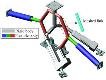
As indicated above, the 4-DOF PDM possesses nine passive redundant constraints. Since the SPU limb own six degrees-of-freedom, the over-constraints are caused by other links besides the SPU limbs. In this section, based on the screw theory, the over-constrained direction is analyzed. Moreover, the over-constraints were verified via the co-simulation with ABAQUS and ADAMS software. First, the flexible links are meshed by hexahedron elements in ABAQUS, and the mnf files of the meshed links are obtained via ABAQUS. Then, loading the link files, rigid links are replaced with flexible bodies in ADAMS. The simulation model is shown as Fig. 14.
Rigid–flexible coupling model of the 4-DOF PDM.

From the above analysis, we know that over-constraints are caused by operating mechanism and two RPR limbs. In order to supplement the deformation coordination equations, we need to further determine the direction of over-constraints. Based on the screw theory, the constraint screw of the limb is as follows:
 \begin{equation} \begin{array}{l} \boldsymbol{\$ }_{1}^{rr}\boldsymbol{=}\left[\begin{array}{l@{\quad}l@{\quad}l@{\quad}l@{\quad}l@{\quad}l} 0 & 0 & 1 & 0 & 0 & 0 \end{array}\right]\\[3pt] \boldsymbol{\$ }_{2}^{rr}\boldsymbol{=}\left[\begin{array}{l@{\quad}l@{\quad}l@{\quad}l@{\quad}l@{\quad}l} 0 & 0 & 0 & 1 & 0 & 0 \end{array}\right]\\[3pt] \boldsymbol{\$ }_{3}^{rr}\boldsymbol{=}\left[\begin{array}{l@{\quad}l@{\quad}l@{\quad}l@{\quad}l@{\quad}l} 0 & 0 & 0 & 0 & 1 & 0 \end{array}\right] \end{array} \end{equation}
As shown in Fig. 15, the operating mechanism and two RPR limbs possess the constrained force along z -axis and constrained couples around x -axis, y -axis, which means each link in the operating mechanism and two RPR limb own three over-constrained motions.
Schematic diagram of over-constrained direction analysis.

5.3. Deformation compatibility equation
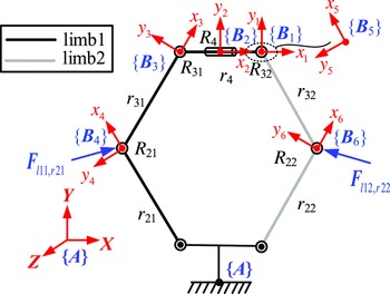
In this section, on the condition of the numbers and direction of over-constraints, we derive the deformation compatibility equation in detail. First, the operating mechanism and two RPR limbs are divided into three modules. Then derive the deformation of each module according to the link’s elastic deformation in Section 5.1. Finally, the deformation compatibility equations are derived at joints
 $R_{21},R_{22}$
, and
 $R_{32}$
.
The elastic deformation of limbs 1 and 2 at joint
 $R_{32}$
as shown in Fig. 16.
Limbs 1 and 2 deformation analysis.

Referring to Eq. (65), we have
 \begin{equation} {}^{B2}{\boldsymbol{F}}{_{R4}^{}}=\boldsymbol{J}_{B2,B1}{}^{B1}{\boldsymbol{F}}{_{r32,r4}^{}}+\boldsymbol{J}_{B2,A}{}^{A}{\boldsymbol{F}}{_{4p}^{}} \end{equation}
 \begin{equation} {}^{B3}{\boldsymbol{F}}{_{r4,r31}^{}}=\boldsymbol{J}_{B3,B2}{}^{B2}{\boldsymbol{F}}{_{R4}^{}} \end{equation}
 \begin{equation} {}^{B4}{\boldsymbol{F}}{_{r31,r21}^{}}=\boldsymbol{J}_{B4,B3}{}^{B3}{\boldsymbol{F}}{_{r4,r31}^{}} \end{equation}
where
 ${}^{B1}{\boldsymbol{F}}{_{r32,r4}^{}}$
is the force applied to link
 $r_{4}$
by link
 $r_{32}$
with respect to the frame {
A
}.
 $\boldsymbol{J}_{B2,A}$
represents the transformation matrix between frame {
B
2} and frame {
A
}.
Based on the Eq. (69), the elastic deformations of the links
 $r_{21}$
and
 $r_{31}$
at the joint
 $R_{31}$
with respect to the frame {
B
3} are
 \begin{equation} {}^{B3}{\boldsymbol{\delta }}{_{R31}^{}}\boldsymbol{=}\boldsymbol{C}_{1}{}^{B3}{\boldsymbol{F}}{_{r4,r31}^{}}+\boldsymbol{J}_{B4,B3}^{T}\left(\boldsymbol{C}_{1}{}^{B4}{\boldsymbol{F}}{_{r31,r21}^{}}+\boldsymbol{C}_{1}{}^{B4}{\boldsymbol{F}}{_{l11,r21}^{}}\right) \end{equation}
Hence, the elastic deformation of the links
 $r_{21},r_{31}$
, and
 $r_{4}$
at the joint
 $R_{32}$
with respect to the frame {
A
} are
 \begin{equation} {}^{A}{\boldsymbol{\delta }}{_{R32\_ \lim b1}^{}}\boldsymbol{=}\boldsymbol{J}_{B1,A}^{T}\left(\boldsymbol{J}_{B3,B1}^{T}{}^{B3}{\boldsymbol{\delta }}{_{R31}^{}}+\boldsymbol{J}_{B2,B1}^{T}\boldsymbol{C}_{2}{}^{B2}{\boldsymbol{F}}{_{R4}^{}}+\boldsymbol{C}_{2}{}^{B1}{\boldsymbol{F}}{_{r32,r4}^{}}\right) \end{equation}
Similarly, the elastic deformation of limb2 at
 $R_{32}$
is given as
 \begin{equation} {}^{B6}{\boldsymbol{F}}{_{r32,r22}^{}}=\boldsymbol{J}_{B6,B5}{}^{B5}{\boldsymbol{F}}{_{r32,r4}^{}} \end{equation}
 \begin{equation} {}^{R22}{\boldsymbol{\delta }}{_{R22}^{}}=\boldsymbol{C}_{1}{}^{B6}{\boldsymbol{F}}{_{r32,r22}^{}}+\boldsymbol{C}_{1}{}^{B6}{\boldsymbol{F}}{_{l12,r22}^{}} \end{equation}
 \begin{equation} {}^{A}{\boldsymbol{\delta }}{_{R32\_ \lim\! b2}^{}}=\boldsymbol{J}_{B5,A}\left(\boldsymbol{J}_{B6,B5}{}^{R22}{\boldsymbol{\delta }}{_{R22}^{}}+\boldsymbol{C}_{1}{}^{B5}{\boldsymbol{F}}{_{r4,r32}^{}}\right) \end{equation}
The deformation caused by limbs 3 and 4 at joint
 $R_{32}$
as shown in Fig. 17.
Limbs 3 and 4 deformation analysis.

Referring to Eq. (69), the elastic deformation of limb 3 at joint
 $R_{21}$
is given as
 \begin{equation} {}^{A}{\boldsymbol{\delta }}{_{R21\_ \lim\! b3}^{}}=\boldsymbol{J}_{B7,A}^{T}\left(\boldsymbol{J}_{B8,B7}^{T}\boldsymbol{C}_{4}\boldsymbol{J}_{B8,B7}\!\left(-{}^{B7}{\boldsymbol{F}}{_{l11,r21}^{}}\right)+\boldsymbol{C}_{3}\!\left(-{}^{B7}{\boldsymbol{F}}{_{l11,r21}^{}}\right)\right) \end{equation}
Similarly, the elastic deformation of limb 4 at joint
 $R_{21}$
is given as
 \begin{equation} {}^{A}{\boldsymbol{\delta }}{_{R21\_ \lim\! b4}^{}}=\boldsymbol{J}_{B4,A}^{T}\!\left(\boldsymbol{C}_{1}{}^{B4}{\boldsymbol{F}}{_{l2,l1}^{}}+\boldsymbol{C}_{1}{}^{B4}{\boldsymbol{F}}{_{l7,l1}^{}}\right) \end{equation}
The deformation caused by limbs 5 and 6 at joint
 $R_{32}$
as shown in Fig. 18.
Limbs 5 and 6 deformation analysis.

Based on the Eq. (69), the elastic deformation of limb 5 at joint
 $R_{22}$
are given as
 \begin{equation} {}^{A}{\boldsymbol{\delta }}{_{R22\_ \lim\! b5}^{}}=\boldsymbol{J}_{B9,A}^{T}\left(\boldsymbol{J}_{B10,B9}^{T}\boldsymbol{C}_{6}\boldsymbol{J}_{B10,B9}\left(-{}^{B9}{\boldsymbol{F}}{_{l12,r22}^{}}\right)+\boldsymbol{C}_{5}\!\left(-{}^{B7}{\boldsymbol{F}}{_{l12,r22}^{}}\right)\right) \end{equation}
Similarly, the elastic deformation of limb 6 at joint
 $R_{22}$
are given as
 \begin{equation} {}^{A}{\boldsymbol{\delta }}{_{R22\_ \lim\! b6}^{}}=\boldsymbol{J}_{B6,A}^{T}\left(\boldsymbol{C}_{1}{}^{B6}{\boldsymbol{F}}{_{r32,r22}^{}}+\boldsymbol{C}_{1}{}^{B6}{\boldsymbol{F}}{_{l12,r22}^{}}\right) \end{equation}
The deformations of the operating mechanism and two RPR limbs have to be compatible with each other to satisfy the geometric constraints. Hence, translational deformation along z and rotational deformation about x and y axis at joints
 $R_{21},R_{22},R_{32}$
should be equal, namely
 \begin{equation} \begin{array}{l} {}^{A}{\boldsymbol{\delta }}{_{R32\_ \lim\! b1}^{}}\left(k,1\right)={}^{A}{\boldsymbol{\delta }}{_{R32\_ \lim\! b2}^{}}\left(k,1\right)\\ {}^{A}{\boldsymbol{\delta }}{_{R21\_ \lim\! b3}^{}}\left(k,1\right)={}^{A}{\boldsymbol{\delta }}{_{R21\_ \lim\! b4}^{}}\left(k,1\right)\left(k=3,4,5\right)\\ {}^{A}{\boldsymbol{\delta }}{_{R22\_ \lim\! b5}^{}}\left(k,1\right)={}^{A}{\boldsymbol{\delta }}{_{R22\_ \lim\! b6}^{}}\left(k,1\right) \end{array} \end{equation}
So far, the complete dynamics models with constrained forces/moments of the over-constrained 4-DOF PDM with sub-closed chains are established. The actuation forces and constrained forces/moments can be obtained simultaneously, which is essential for structure design. Also, clearance and friction can be easily integrated into the system equation.
6. Simulation and experiment
We set the trajectory of the end-effector of the manipulator with respect to the inertial reference frame P -xyz as follows:
 \begin{equation} \begin{array}{l} \begin{array}{ll} x\!\left(t\right)=S_{x}\!\left(\dfrac{t}{T}-\dfrac{1}{2\pi }\sin\! \left(2\pi \dfrac{t}{T}\right)\right) & t\in \left[0,T\right] \end{array}\\[1em] \begin{array}{ll} y\!\left(t\right)=S_{y}\!\left(\dfrac{t}{T}-\dfrac{1}{2\pi }\sin\! \left(2\pi \dfrac{t}{T}\right)\right) & t\in \left[0,T\right] \end{array}\\[1em] \begin{array}{ll} \alpha\! \left(t\right)=S_{\alpha }\!\left(\dfrac{t}{T}-\dfrac{1}{2\pi }\sin\! \left(2\pi \dfrac{t}{T}\right)\right) & t\in \left[0,T\right] \end{array}\\[1em] \begin{array}{ll} \gamma\! \left(t\right)=S_{\gamma }\!\left(\dfrac{t}{T}-\dfrac{1}{2\pi }\sin\! \left(2\pi \dfrac{t}{T}\right)\right) & t\in \left[0,T\right] \end{array} \end{array} \end{equation}
where
 $S_{x}$
and
 $S_{y}$
denote the displacement along the x-axis and y-axis with respect to the fixed reference coordinate system,
 $S_{\alpha }$
and
 $S_{\gamma }$
denote the angle along the x-axis and z-axis with respect to the fixed reference coordinate system, respectively.
6.1. Simulation validation
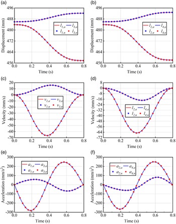
According to the derivation of the above formula, the displacements, velocities, accelerations, driving forces, and all constraint forces/moments of the 4-DOF PDM are obtained. The numerical simulation results are qualitatively consistent with the theoretical results. As shown in Fig. 19,
 $l_{1,a}, v_{1,a}$
, and
 $a_{1,a}$
(i = 1, 2, 3, 4) denote the theoretical displacements, velocities, and accelerations of the slider respectively.
 $l_{i,n}, v_{i,n}$
, and
 $a_{i,n}$
(i = 1, 2, 3, 4) denote the numerical displacements, velocities, and accelerations of the slider, respectively.
Numerical and theoretical results of displacement/velocity/acceleration.

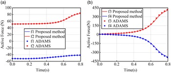
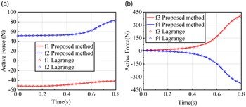
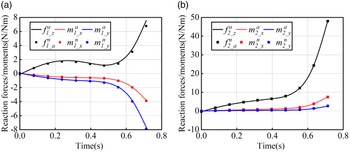
The results of co-simulation with ADAMS and ABAQUS are shown in Fig. 14. Figure 20 shows the active forces computed by the proposed method and ADAMS; Figure 21 shows the active forces computed by the proposed method and Lagrangian method; Figure 22(a) and (b) show the constraint forces/moments in the over-constrained direction at joints
 $R_{32}$
and
 $R_{21}$
, respectively.
 $f_{i\_ z}^{a},m_{i\_ x}^{a}$
and
 $m_{i\_ y}^{a}(i=1,2)$
represent the theoretical value and
 $f_{i\_ z}^{n},m_{i\_ x}^{n}$
and
 $m_{i\_ y}^{n}(i=1,2)$
represent the simulation value.
Active forces computed by the proposed method and ADAMS.

Active forces computed by the proposed method and Lagrangian method.

Partial constraint forces/moments simulation and theoretical value.

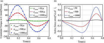
It is assumed that the cylinders and pistons are symmetrically distributed in this paper. That is, the influence of the eccentricity of the electric cylinder on the constraint torque at the U-joint is not considered. In order to verify the influence of acceleration on the constraint torque and driving force at the U-joint, the constraint torques at the U-joint are calculated when the maximum translational acceleration along y-axis is up to 50, 500, and 1000 mm/s2. Moreover, the driving forces are solved with and without constraint torque at the U-joint, and the driving forces error percentage are plotted as shown in Fig. 23(b).
Constraint torque at U-joint and driving force error percentage under different accelerations.

6.2. Experiment validation
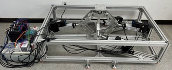
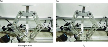
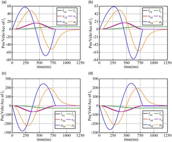
According to the CAD model displayed in Fig. 1, a physical prototype has been built for the motion control experiment. As shown in Fig. 24, actuators are driven by the electric piston-cylinder, which are connected to an embedded controller (CX5130) made by the company Beckhoff through an Ethercat bus. Based on the position loop mode PID controller to achieve the target trajectory, it is one of the commonly used controllers in academic research and industrial products. The motion control experiment based on PID controller is shown in Figure 25. The measured values of displacements, velocities, and accelerations of the four driving limbs are shown in Fig. 26, which are consistent with the theoretical calculation.
Physical prototype and control system.

Trajectory planning based on classical PID control.

In this paper, the control cycle of the embedded controller (CX5130) is 2 ms. As shown in Fig. 26, the measured position and velocity of the four driving limbs are consistent with the theoretical value, but the lag of phase is 20 ms. Due to the short control cycle, the position signal obtained by the encoder undergoes two differential and filtering processes, resulting in significant signal distortion. As shown in Fig. 26, the measured acceleration not only have phase lag but also have attenuation in amplitude.
7. Conclusion
In this paper, a 4-DOF over-constrained PDM with sub-closed chains is proposed and its prototype is developed. By considering the flexibility of the operating mechanism and two RPR limbs, the deformation compatibility condition is introduced to solve a statically indeterminate problem. The actuation forces and constrained forces/moments are obtained simultaneously, which is conducive to the design of the PDM.
In the symmetrical structure of the electric piston-cylinder, the value of constraint moments at the U-joint under different accelerations is analyzed by taking into account its impact on driving forces. According to the results of comparative experiment conducted on the end-effector under different accelerations in a certain direction, the impact on the active force is about 1%, regardless of the constraint moment at the U-joint. The effectiveness of the kinematic model is demonstrated by ADAMS and the experiment based on classical PID control, while that of the dynamic model is confirmed by the co-simulation with MATLAB, ADAMS and ABAQUS. In addition, the actuation forces are also verified by using the Lagrangian method. The present study provides a valuable reference for future study on structural optimization. In future studies, the rigid–flexible coupling dynamic model will also be established to obtain rigid–flexible coupling dynamic characteristics and an accurate constraint forces/moments.
Measured and theoretical results of displacement/velocity/acceleration.

Availability of data and materials
The datasets used and/or analyzed during the current study are available from the corresponding author on reasonable request.
Author contribution
Yangyang Huang, Jinzhu Zhang, and Xiaoyan Xiong conceived and designed the study. Shengxiang Liu conducted data gathering. Yangyang Huang wrote the article.
Financial support
The authors would like to acknowledge (1) Project (51905367) supported by The National Nature Science Foundation of China, (2) Project (201901D211011) supported by The Foundation of Applied Basic Research General Youth Program of Shanxi.
Competing interests
The authors declare no competing interests exist.
Ethical approval
Not applicable.
Appendix A
The kinematic and dynamic parameters of the PDM virtual prototype used in the simulation are as follows (default in mm unit):
 \begin{align*} & r_{0}=73.5,r_{1}=180,r_{2i}=r_{3i}=240,r_{4}=180,g_{1}=110.10719,g_{2}=346.80127,g_{3}=285.26279,\\& g_{4}=99.91525, E=7.1705e+4\left(Mpa\right),u=0.33,G=E/\left(2\left(1+\mu \right)\right),D_{1}=35,D_{2}=60,D_{3}=30 \end{align*}
Appendix B
 \begin{align*} a_{1i} & = r_{2i}\!\left(x_{R3i}+\left(-1\right)^{i+1}r_{1}/2\right)\\ b_{1i} & = r_{2i}\!\left(y_{R3i}-n_{1}\right)\\ d_{li} & = r_{2i}^{2}/2-\left(x_{R3i}+\left(-1\right)^{i+1}r_{1}/2\right)^{2}/2+\left(y_{R3i}-n_{1}\right)^{2}/2\\ & \quad -\left(r_{3i}\right)^{2}/2+\left(x_{R3i}+\left(-1\right)^{i+1}r_{1}/2\right)\left(x_{R3i}+\left(-1\right)^{i+1}r_{1}/2\right) \end{align*}
The inertial parameters of the PDM.