I. INTRODUCTION
It is desirable to design materials with low or zero coefficients of thermal expansion (CTEs) for applications that involve large temperature variations, to reduce thermal stresses and maintain geometric stability. Traditionally the thermal expansion of composite materials is considered to be a weighted average of the thermal expansion coefficients of the constituent materials. For two-phase composites with constituents that are assumed to be isotropic, have positive definite strain energy, and are not porous, the overall thermal expansion is a weighted average based on the constituent volume fractions and bulk moduli.Reference Cribb1 It is possible by evading these assumptions, combined with tailored design of the material’s microstructure to obtain large or even negative values of thermal expansion, with positive constituent CTEs.Reference Lakes2,Reference Lakes3
For use in structural applications, material stiffness optimization is often required. In general, three-dimensional foams (in any direction) and hexagonal honeycombs (in-plane) deform mainly by bending of cell walls.Reference Gibson, Ashby, Clarke, Suresh and Ward4 This gives rise to a modulus that is quadratic in relative density. Relative density is the density of the porous material divided by the density of the solid phase that comprises the ribs. To optimize material stiffness, lattices are chosen so that the material deformation is axial rather than bending. In such stretch-dominated lattices, the modulus is linear in relative density. For low density, such lattices are much stiffer than foams. Axial deformation is achieved by specifying equilateral triangular honeycombs and octet-truss three-dimensional lattices. Prior studies analytically described zero thermal expansion with the use of two-dimensional triangular honeycomb composed of curved bi-material rib elements.Reference Lehman and Lakes5 These lattices were optimized for stiffness by further design of the dimensions of the rib cross-sections.Reference Lehman and Lakes6 The present research obtains zero thermal expansion, with the use of Poisson contraction. By the use of this method, it is possible to utilize tube elements as the structural member of lattices. The use of straight, as opposed to curved, rib elements eliminates the bending load applied to each member and thus improves stiffness. This stiffness benefit is offset, somewhat, by additional constituent mass, required for zero expansion, but does not participate structurally. Additionally, tubes are geometrically advantageous to resist buckling, increasing the strength of the lattice material.
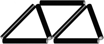
Poisson contraction in the longitudinal direction can be achieved by using two concentric tubes in two different configurations. In the first configuration, material two is press fitted over material one, where material one has a smaller CTE than material two. The press fit will initially compress material one circumferentially, causing an initial lengthening in the longitudinal direction. As a temperature difference is applied, the outer tube (material two) will expand more rapidly than the inner tube, reducing the initial stress caused by the press fit. This change in transverse stress will allow material one to contract in the longitudinal direction, as the initial extension from the prestress Poisson effect is reduced. This provides control of thermal expansion. Reduced expansion via a bi-material concentric tubular geometry was first described by Baird.Reference Baird7 A second configuration exists where material two is used as the inner tube. In this configuration, no initial prestress is required. As the temperature increases the inner tube (material two) will expand more than the outer tube. This will cause circumferential tension in material one providing a longitudinal Poisson contraction. Both configurations can be analyzed as one, with the assumption of thin walls. In both cases, the longitudinal Poisson contraction acts to counteract the longitudinal thermal expansion. The system is first restricted to isotropic materials and then the analysis is expanded to include anisotropic materials. Figure 1 depicts a two-dimensional triangular lattice composed of bi-material, concentric tube elements; three-dimensional lattices are also analyzed.
A two-dimensional triangular lattice constructed of bi-material concentric tubular elements. The geometry of the nodes is not shown for simplicity.

II. MATERIALS CONSIDERED AND THEIR PROPERTIES
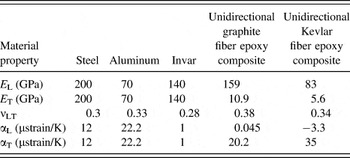
To characterize zero expansion lattices, a variety of materials were considered for lattice constituents. Three isotropic materials studied include steel, aluminum, and Invar. Invar is known for its low CTE, whereas steel and aluminum are commonly used for structural materials and have differing thermal expansion coefficients. Two anisotropic unidirectional fiber composites were also considered, a graphite fiber epoxy composite and a Kevlar fiber epoxy composite. The fibers are aligned in the longitudinal direction with respect to the matrix, whereas the transverse direction is considered to be orthogonal to the axis of the fibers. The material properties used for each material are shown in Table I in which E is Young’s modulus, ν is Poisson’s ratio, and α is thermal expansion. The properties used are obtained as follows. The properties of Invar were obtained from Woolger,Reference Woolger8 the properties for Kevlar and graphite epoxy composites are from Agarwal and Broutman.Reference Agarwal and Broutman9 The thermal properties for aluminum and steel come from the ASM International Materials Properties Database Committee,10 whereas the mechanical properties of aluminum and steel are from Cook and Young.Reference Cook and Young11
A list of material properties used throughout the analysis. For fiber-reinforced composites, the L subscript indicates the direction along the fibers, whereas T denotes the direction transverse to that of the fibers. Steel, aluminum, and Invar are considered isotropic and are only defined by one Young’s modulus and one CTE.

III. THERMAL EXPANSION ANALYSIS
This first analysis assumes that the materials are isotropic. The following assumptions are also made. The materials are perfectly bonded at their interface so that all strain values are equal at the contact surface, specifically, in both longitudinal and circumferential directions. The walls of both tubes are assumed to be thin in comparison to their diameter. This means that the tube radii are considered equal and all radial stresses are neglected. The following subscripts are used throughout the analysis, L, C, R, 1, and 2. L denotes the longitudinal direction, C the circumferential direction, R the radial direction, and 1 and 2 represent materials one and two, respectively. Useful dimensionless parameters (d and n) are defined as follows:
 $$d = {{t_{\rm{1}} } \mathord{\left/ {\vphantom {{t_{\rm{1}} } {t_2 }}} \right. \kern-\nulldelimiterspace} {t_2 }};n = {{E_1 } \mathord{\left/ {\vphantom {{E_1 } {E_2 }}} \right. \kern-\nulldelimiterspace} {E_2 }}\quad ,\,$$
where t 1 and t 2 are material one’s and two’s thicknesses, and E 1 and E 2 are the Young’s Moduli for material one and two, respectively.
A. Isotropic results
From Hooke’s law for plane stress, the strain equations for the circumferential direction can be written for both materials as shown in Eqs. (1) and (2)
 $${\rm{\varepsilon }}_{{\rm{C1}}} = {{\left( {{\rm{\sigma }}_{{\rm{C1}}} - {\rm{\nu }}_{\rm{1}} {\rm{\sigma }}_{{\rm{L1}}} } \right)} \over {E_{\rm{1}} }} + {\rm{\alpha }}_{\rm{1}} \Delta T\quad ,$$
 $${\rm{\varepsilon }}_{{\rm{C2}}} = {{\left( {{\rm{\sigma }}_{{\rm{C2}}} - {\rm{\nu }}_{\rm{2}} {\rm{\sigma }}_{{\rm{L2}}} } \right)} \over {E_{\rm{2}} }} + {\rm{\alpha }}_{\rm{2}} \Delta T\quad ,$$
in which ν1 and ν2 are the Poisson ratios for materials one and two, α1 and α2 are the CTEs for materials one and two, and ΔT is the change in temperature applied to the system. Stresses are denoted by σ. The circumferential and longitudinal stresses of materials one and two can be related by assuming thin-walled stress values where the radii are set equal for both materials and by utilizing force equilibrium. The axial force as a result of CTE mismatch is equal and opposite in materials one and two. Additionally, the pressure at the interface surface of the material acts equally on material one and two. Equations (3) and (4), relating the stresses of materials one and two to one another, can be derived from these principles
 $${\rm{\sigma }}_{{\rm{C2}}} = - d{\rm{\sigma }}_{{\rm{C1}}} \quad ,$$
 $${\rm{\sigma }}_{{\rm{L2}}} = - d{\rm{\sigma }}_{{\rm{L1}}} \quad .$$
As a result of the no slip condition at the interface surface, the strains of Eqs. (1) and (2) can be set equal to each other. Solving for σC1 and substituting Eqs. (3) and (4), the following relationship is obtained
 $${\rm{\sigma }}_{{\rm{C1}}} = {{\left( {{\rm{\alpha }}_{\rm{2}} - {\rm{\alpha }}_{\rm{1}} } \right)E_{\rm{1}} \Delta T + {\rm{\sigma }}_{{\rm{L1}}} \left( {{\rm{\nu }}_{\rm{1}} + nd{\rm{\nu }}_{\rm{2}} } \right)} \over {{\rm{1}} + nd}}\quad .$$
The same approach is taken with the longitudinal strain values, using Hooke’s law for plane strain. Equations (6) and (7) are written for materials one and two
 $${\rm{\varepsilon }}_{{\rm{L1}}} = {{\left( {{\rm{\sigma }}_{{\rm{L1}}} - {\rm{\nu }}_{\rm{1}} {\rm{\sigma }}_{{\rm{C1}}} } \right)} \over {E_{\rm{1}} }} + {\rm{\alpha }}_{\rm{1}} \Delta T\quad ,$$
 $${\rm{\varepsilon }}_{{\rm{L2}}} = {{\left( {{\rm{\sigma }}_{{\rm{L2}}} - {\rm{\nu }}_{\rm{2}} {\rm{\sigma }}_{{\rm{C2}}} } \right)} \over {E_{\rm{2}} }} + {\rm{\alpha }}_{\rm{2}} \Delta T\quad .$$
By setting Eqs. (6) and (7) equal and substituting Eqs. (3) and (4), a relationship relating longitudinal stress of material one to the circumferential stress of material one is obtained
 $${\rm{\sigma }}_{{\rm{L1}}} = {{\left( {{\rm{\alpha }}_{\rm{2}} - {\rm{\alpha }}_{\rm{1}} } \right)\Delta TE_{\rm{1}} + {\rm{\sigma }}_{{\rm{C1}}} \left( {{\rm{\nu }}_{\rm{1}} + \nu _{\rm{2}} nd} \right)} \over {{\rm{1}} + nd}}\quad .$$
To obtain a relationship for longitudinal stress of material one, substitute Eq. (5) into Eq. (8)
 $${\rm{\sigma }}_{{\rm{L1}}} = {{\left( {{\rm{\alpha }}_{\rm{2}} - {\rm{\alpha }}_{\rm{1}} } \right)\Delta TE_{\rm{1}} + \left[ {{\rm{1}} + nd + {\rm{\nu }}_{\rm{1}} + {\rm{\nu }}_{\rm{2}} nd} \right]} \over {\left( {{\rm{1}} + nd} \right)^{\rm{2}} = \left( {{\rm{\nu }}_{\rm{1}} + {\rm{\nu }}_{\rm{2}} nd} \right)^{\rm{2}} }}\quad .$$
The total CTE is obtained by dividing the longitudinal strain of material one by the change in temperature. Equation (10) is obtained by substituting Eqs. (5) and (9) into Eq. (6), then dividing by the change in temperature, ΔT
 $${\rm{\alpha }}_{{\rm{struct}}} = \left( {{\rm{\alpha }}_{\rm{1}} - {\rm{\alpha }}_{\rm{2}} } \right)\left[ {{{\left( {{\rm{1}} + nd + {\rm{\nu }}_{\rm{1}} + {\rm{\nu }}_{\rm{2}} nd} \right)\left( {{{{\rm{\nu }}_{\rm{1}} \left( {{\rm{\nu }}_{\rm{1}} + {\rm{\nu }}_{\rm{2}} nd} \right)} \over {{\rm{1}} + nd}} - {\rm{1}}} \right)} \over {\left( {{\rm{1}} + nd} \right)^{\rm{2}} - \left( {{\rm{\nu }}_{\rm{1}} + {\rm{\nu }}_{\rm{2}} nd} \right)^{\rm{2}} }} + {{{\rm{\nu }}_{\rm{1}} } \over {{\rm{1}} + nd}}} \right] + {\rm{\alpha }}_{\rm{1}} \quad .$$
The above relationship represents the overall structural thermal expansion of the system. To gain insight into the possible values of αstruct, three specific cases are studied. The first is to set both Poisson ratios equal to one another resulting in Eq. (11). This case approximates a material choice with similar Poisson ratios, such as two metals. The second case is to set ν1 equal to zero, resulting in Eq. (12). The third case, resulting in Eq. (13), is to set ν2 equal to zero. Studying these three cases illustrates the role of the constituents’ Poisson ratios, on the overall expansion coefficient.
 $$\left. {{\rm{\alpha }}_{{\rm{struct}}} } \right|_{{\rm{\nu }}_{\rm{1}} = {\rm{\nu }}_{\rm{2}} } \,= {{{\rm{\alpha }}_{\rm{1}} nd + {\rm{\alpha }}_{\rm{2}} } \over {{\rm{1}} + nd}}\quad ,$$
 $$\left. {{\rm{\alpha }}_{{\rm{struct}}} } \right|_{{\rm{\nu }}_{\rm{1}} = 0} \,\,= {{{\rm{\alpha }}_{\rm{1}} nd\left( {{\rm{1}} - {\rm{\nu }}_{\rm{2}} } \right) + {\rm{\alpha }}_{\rm{2}} } \over {{\rm{1}} + nd\left( {{\rm{1}} - {\rm{\nu }}_{\rm{2}} } \right)}}\quad ,$$
 $$\left. {{\rm{\alpha }}_{{\rm{struct}}} } \right|_{{\rm{\nu }}_{\rm{2}} = 0} \,\,= {{{\rm{\alpha }}_{\rm{1}} nd + {\rm{\alpha }}_{\rm{2}} \left( {{\rm{1}} - {\rm{\nu }}_{\rm{2}} } \right)} \over {{\rm{1}} + nd - {\rm{\nu }}_{\rm{1}} }}\quad .$$
The simplification given by Eq. (11) is a weighted average of the two component CTEs based on relative thicknesses and Young’s modulus. Equations (12) and (13) are also weighted averages but are shifted further by the nonzero Poisson ratios. In all three cases, it is not possible to obtain negative or zero thermal expansion without the use of negative thermal expansion materials.
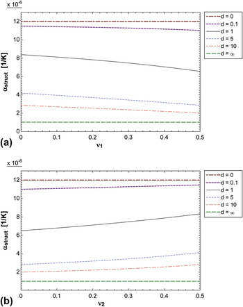
A parametric study of Eq. (10) was conducted where the constituents’ CTEs, stiffness ratio (n), and one constituent’s ν were held constant while the other constituent’s Poisson ratio was varied from zero to one half. A second parametric study varied the other constituent’s Poisson ratio while holding all other parameters constant. Both studies also considered different material thickness ratios. These two parametric studies did not identify a pair of Poisson ratios that allow for zero overall expansion. The limits achieved were those of the material constituent CTEs. Figures 2(a) and 2(b) provide plots of the structural thermal expansion versus the varied Poisson ratio, with the stiffness ratio (n) equal to 1.7, the constituent thermal expansion values equal to 12 and 1 μstrain/K, and the unvaried Poisson ratio equal to 0.3.
(a) Structural thermal expansion for isotropic fully bonded tubes, α1 = 1 μstrain/K, α2 = 12 μstrain/K, ν2 = 0.3, n = 1.7, ν1 and thickness ratio d are varied. (b) Structural thermal expansion for isotropic bonded tubes with the same properties as (a) but ν1 = 0.3 and ν2 and d are varied.

This suggests that for any two isotropic materials, as nested tubes, with a fully bonded no slip interface, it is likely not possible to obtain a CTE less than the smallest or greater than the largest component CTE. Thus, zero thermal expansion was not obtained over a range of parameter space with isotropic, perfectly bonded tubes via Poisson contraction, without one constituent material having a negative CTE.
B. Anisotropic results
Because current parametric studies have not obtained zero CTE with bonded isotropic materials of equal length and positive constituent CTEs, it is expedient to relax the assumption of isotropy or the assumption of perfect bonding. Anisotropic materials such as fiber-reinforced composites may allow the CTE to approach zero or even become negative. Assumptions for the anisotropic case still include thin walls, and a no slip material interface. The same approach used for the isotropic analysis is used here. The strain for both materials in both longitudinal and circumferential directions is written with Hooke’s law. The strains for each direction are constrained to be equal in both materials, and the expansion coefficient is taken to be the longitudinal strain of material one divided by the change in temperature.
The following new terms are defined for the anisotropic solution. E L1 and E L2 are the Young’s moduli in the longitudinal direction for materials one and two. E C1 and E C2 are the Young’s moduli in the circumferential direction for materials one and two. αL1 and αL2 are the thermal expansion coefficients in the longitudinal direction for materials one and two. αC1 and αC2 are the thermal expansion coefficients in the circumferential direction for materials one and two. The Poisson ratios are defined with three subscripts as follows: the third subscript is either one or two and indicates material. The first and second subscripts are either L or C and indicate the direction. The Poisson ratio for anisotropy is defined as follows:
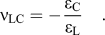 $${\rm{\nu }}_{{\rm{LC}}} = - {{{\rm{\varepsilon }}_{\rm{C}} } \over {{\rm{\varepsilon }}_{\rm{L}} }}\quad .$$
The thickness ratio is still defined as d. The moduli ratio n is replaced with two ratios given in Eq. (15)
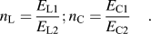 $$n_{\rm{L}} = {{E_{{\rm{L1}}} } \over {E_{{\rm{L2}}} }};n_{\rm{C}} = {{E_{{\rm{C1}}} } \over {E_{{\rm{C2}}} }}\quad .$$
The anisotropic solution for overall thermal expansion is given by Eq. (16). By replacing all anisotropic properties with isotropic ones, Eq. (16) reduces to the isotropic form given by Eq. (10)
 $${\rm{\alpha }}_{{\rm{struct}}} = \,\,{\rm{\alpha }}_{{\rm{L1}}} + {{{\rm{\nu }}_{{\rm{LC1}}} E_{{\rm{C1}}} \left( {{\rm{\alpha }}_{{\rm{C1}}} - {\rm{\alpha }}_{{\rm{C2}}} } \right)} \over {E_{{\rm{L1}}} \left( {{\rm{1}} + n_{\rm{C}} d} \right)}} + \left[ {{\rm{1}} - {{{\rm{\nu }}_{{\rm{LC1}}} \left( {{\rm{\nu }}_{{\rm{LC1}}} + {\rm{\nu }}_{{\rm{LC2}}} n_{\rm{C}} d} \right)} \over {{\rm{1}} + n_{\rm{C}} d}}} \right] \left[ {{{\left( {{\rm{\alpha }}_{{\rm{L2}}} - {\rm{\alpha }}_{{\rm{L1}}} } \right)\left( {{\rm{1}} + n_{\rm{C}} d} \right) + {{E_{{\rm{C1}}} } \over {E_{{\rm{L1}}} }}\left( {{\rm{\alpha }}_{{\rm{C2}}} - {\rm{\alpha }}_{{\rm{C1}}} } \right)\left( {{\rm{\nu }}_{{\rm{LC1}}} + {\rm{\nu }}_{{\rm{LC2}}} n_{\rm{L}} d} \right)} \over {\left( {{\rm{1}} + n_{\rm{C}} d} \right)\left( {{\rm{1}} + n_{\rm{L}} d} \right) - \left( {{\rm{\nu }}_{{\rm{LC1}}} + {\rm{\nu }}_{{\rm{LC2}}} n_{\rm{L}} d} \right)\left( {{\rm{\nu }}_{{\rm{CL1}}} + {\rm{\nu }}_{{\rm{CL2}}} n_{\rm{C}} d} \right)}}} \right]\quad . \cr}$$
Two anisotropic materials were considered in attempting to achieve zero thermal expansion: the first material considered is a unidirectional graphite-epoxy fiber composite, whereas the second is a unidirectional Kevlar-epoxy fiber composite. Both materials are paired with Invar, which has a small CTE. The Kevlar-epoxy composite is notable for having a negative thermal expansion in the longitudinal direction. For each material, two fiber orientations are considered: axially oriented and circumferentially oriented fibers. Graphite fiber epoxy and Invar do not allow for zero structural thermal expansion, regardless of the fiber orientation. The end result is a weighted average of the two material CTEs. By using Kevlar-epoxy with the fibers oriented along the axis of the tube, zero expansion is attainable due to the negative thermal expansion of the Kevlar-epoxy composite. The thickness ratio of Invar to Kevlar composite is 1.88, corresponding to a tube that is 65.3% by volume Invar.
C. Results for tube with decoupled layers
It is possible to achieve zero expansion of nested tubes made of positive expansion materials if the axial deformation of the layers is decoupled. One way is to provide a layer of lubricant between the layers so that a radial constraint is imposed but longitudinal deformation of each layer is free to occur. Another way is to segment one layer into rings or wire wrap. In that vein, a configuration specified by the Baird patent describes an Invar tube for material one and a steel wire wrapped helically for material two.Reference Baird12 Using a steel wire as opposed to a solid wall steel tube reduces the contact area between the two materials. Reducing the contact also reduces the strain in the longitudinal direction as a result of the larger CTE material pulling on the smaller CTE material. This allows for effectively zero thermal expansion and zero stiffness contribution of the steel in the longitudinal direction, while still providing adequate stiffness in the circumferential direction. The structure is analyzed with similar methods, as before, but accounting for variable contact area and assuming perfect slip conditions. This means that the longitudinal stiffness of material two (the outer material) is treated as zero and its thermal expansion in the longitudinal direction is also neglected. In addition, stress concentrations are neglected and loads are distributed evenly over contact surfaces. These assumptions are considered to be consistent with both methods of decoupling axial deformation and are recognized to be idealized conditions.
An anisotropic analysis was performed allowing for materials one and two to differ in length. The analysis defines a new ratio, l, which is equal to the total length of material two divided by the total length of material one. The derivation relies on the assumption that the axial stress and strain of the two materials are independent and are allowed to slide relative to one another. This assumption is best approximated for small l values. Equation (17) provides the overall CTE for the anisotropic case allowing for different material lengths
 $${\rm{\alpha }}_{{\rm{struct}}} = {\rm{\alpha }}_{{\rm{L1}}} + {{{\rm{\nu }}_{{\rm{CL1}}} \left( {{\rm{\alpha }}_{{\rm{C1}}} - {\rm{\alpha }}_{{\rm{C2}}} } \right)} \over {{\rm{1}} + {{n_{\rm{C}} d} \over l}}}\quad .$$
For the isotropic case, the above relationship reduces to Eq. (18)
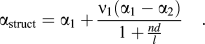 $${\rm{\alpha }}_{{\rm{struct}}} = {\rm{\alpha }}_{\rm{1}} + {{{\rm{\nu }}_{\rm{1}} \left( {{\rm{\alpha }}_{\rm{1}} - {\rm{\alpha }}_{\rm{2}} } \right)} \over {{\rm{1}} + {\textstyle{{nd} \over l}}}}\quad .$$
By cutting the structure along its lengthwise direction, the cross-sectional area of each material is equal to its length times twice its thickness, thus  ${{A_{\rm{1}} } \over {A_{\rm{2}} }} = {d \over l}$ where A 1 and A 2 are the cross-sectional areas for materials one and two. Using this relationship and setting, the overall expansion coefficient equal to zero in Eq. (18) and Eq. (19) is obtained
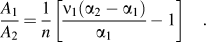 $${{A_{\rm{1}} } \over {A_{\rm{2}} }} = {{\rm{1}} \over n}\left[ {{{{\rm{\nu }}_{\rm{1}} \left( {{\rm{\alpha }}_{\rm{2}} - {\rm{\alpha }}_{\rm{1}} } \right)} \over {{\rm{\alpha }}_{\rm{1}} }} - {\rm{1}}} \right]\quad .$$
Equation (19) is equivalent to the formula given by Baird.Reference Baird7 A similar relationship for the anisotropic case can be derived. Equation (20) provides a formula for calculating the required area ratio from material properties to achieve zero thermal expansion
 $${{A_{\rm{1}} } \over {A_{\rm{2}} }} = {{\rm{1}} \over {n_{\rm{C}} }}\left[ {{{{\rm{\nu }}_{{\rm{CL1}}} \left( {{\rm{\alpha }}_{{\rm{C2}}} - {\rm{\alpha }}_{{\rm{C1}}} } \right)} \over {{\rm{\alpha }}_{{\rm{L1}}} }} - {\rm{1}}} \right]\quad .$$
Making use of the above equations, it is possible to compare different material combinations. The area ratio is equivalent to the material volume ratio due to the radial symmetry of the structure and thin wall assumption.
IV. 2D TRIANGULAR HONEYCOMB LATTICE STIFFNESS ANALYSIS
Zero expansion lattices are envisaged based on these nested tube elements as lattice ribs. For example, to optimize stiffness, while maintaining low or zero thermal expansion, the tubular elements can be arranged in a 2D triangular honeycomb lattice, as shown in Fig. 1. Poisson contraction neutralizes the thermal expansion of each element, which neutralizes expansion of the lattice as a whole. The in-plane stiffness of the honeycomb lattice (E h) composed of zero expansion tubes can be analytically determined by following the approach used by Hunt.Reference Hunt13 This analysis assumes that the elements are pin connected, that is joints can rotate freely, and all loads are carried axially, bending moments are neglected. Additionally, the mass of material two is assumed to not participate structurally. All forces are carried by the tubular element composed of material one. The honeycomb structural stiffness is given by Eq. (21)
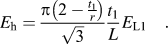 $$E_{\rm{h}} = {{{\rm{\pi }}\left( {{\rm{2}} - {{t_{\rm{1}} } \over r}} \right)} \over {\sqrt {\rm{3}} }}{{t_{\rm{1}} } \over L}E_{{\rm{L1}}} \quad .$$
The thickness of material one is given as t 1 and the length of the tubular element is L while the radius of the tube element is r. To compare this stiffness to that previously obtained, zero expansion lattices in a meaningful way, it is necessary to normalize the honeycomb stiffness by the stiffness (E s) of a solid made of equal proportions of material one and two as the zero expansion lattice. The solid stiffness is considered as that of a Voigt composite and is given by Eq. (22)
 $$E_{\rm{s}} = {{E_{{\rm{L2}}} \left[ {n_{\rm{L}} \nu _{{\rm{CL1}}} \left( {{\rm{\alpha }}_{{\rm{C2}}} - {\rm{\alpha }}_{{\rm{C1}}} } \right) + {\rm{\alpha }}_{{\rm{L1}}} \left( {n_{\rm{C}} - n_{\rm{L}} } \right)} \right]} \over {{\rm{\nu }}_{{\rm{CL1}}} \left( {{\rm{\alpha }}_{{\rm{C2}}} - {\rm{\alpha }}_{{\rm{C1}}} } \right) + {\rm{\alpha }}_{{\rm{L1}}} \left( {n_{\rm{C}} - {\rm{1}}} \right)}}\quad .$$
The relative density must also be determined to allow for an accurate comparison between lattices. To compute relative densities, material located at the nodes is ignored. This approximation works well for length to radius (aspect) ratios that are sufficiently large. This analysis only considers slender aspect ratios equal to and greater than eight. Equation (23) provides the relative density ratio for tubular, triangular honeycomb lattices with zero thermal expansion
 $${{{\rm{\rho }}^{\rm{*}} } \over {{\rm{\rho }}_{\rm{s}} }} = \sqrt 3 {\rm{\pi }}{{t_1 } \over L}\left( {2 - {{t_1 } \over r}} \right)\left( {1 + {{{\rm{\alpha }}_{{\rm{L1}}} n_{\rm{C}} } \over {{\rm{\nu }}_{{\rm{CL1}}} \left( {{\rm{\alpha }}_{{\rm{C2}}} - {\rm{\alpha }}_{{\rm{C1}}} } \right) - {\rm{\alpha }}_{{\rm{L1}}} }}} \right)\quad .$$
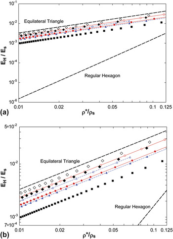
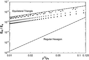
By plotting the honeycomb stiffness obtained from Eq. (21) divided by the solid stiffness of Eq. (22) versus the relative density of Eq. (23), a stiffness density plot is made which can compare the Poisson contraction of tubular lattices to the previously studied curved bi-material lattices. Figure 3 provides a stiffness density plot of both tubular honeycomb lattices and curved bi-material honeycomb lattices, which have previously been described.Reference Lehman and Lakes6 Each lattice, represented with symbols, is analytically tailored for zero thermal expansion. Thick dashed lines indicate triangular and regular hexagonal honeycomb lattices made of straight solid elements. These lattices are characterized after Gibson and AshbyReference Gibson, Ashby, Clarke, Suresh and Ward4 and do not have tailored zero thermal expansion. The triangular nonzero expansion lattice represents an optimally stiff two-dimensional lattice, whereas the regular hexagonal lattice is least optimal in terms of stiffness. The triangular lattice is optimally stiff as a result of its substructure distributing all applied loads axially. The hexagonal lattice substructure however is dominated by bendingReference Gibson, Ashby, Clarke, Suresh and Ward4; hence, hexagonal honeycombs are compliant for deformation in-plane. The node condition for hexagonal lattices differs from that of the triangular honeycombs; angles of ribs at nodes are fixed.
(a) Relative stiffness versus relative density for seven zero expansion lattices. All lattices, except where indicated, are composed of steel and Invar. Thick dashed lines indicate triangle and regular hexagonal honeycombs of nonzero thermal expansion. Squares indicate curved bi-material zero expansion lattices with square cross-sections optimally stiff with a 1/t = 46%. Closed and open triangles with dashed lines indicate optimally stiff zero expansion curved bi-material Tee-shaped lattices with j values of 5 and 20, respectively, and a 1/t values of 23% and 11%, respectively. Closed and open circles with solid lines indicate optimally stiff zero expansion curved bi-material I-shaped lattices with j values of 5 and 20, respectively, k 2 values of 0.28 and 0.17, k 1 values of 1, and a 1/t values of 23% and 11%, respectively. Solid diamonds indicate zero expansion Poisson contraction lattices composed of Invar tubes wrapped with steel wire and a t/r value of 1/20. Open diamonds indicate zero expansion Poisson contraction lattices composed of Invar tubes wrapped with aluminum wire and a t/r value of 1/20. (b) An identical plot as (a) with a restricted y-axis to enhance clarity.

Tubular triangular lattices that utilize Poisson contraction can analytically achieve zero thermal expansion while remaining optimally stiff. They suffer a slight penalty in relative stiffness for a given relative density due to the fact that the ancillary material does not participate structurally but still contributes to the overall weight of the lattice. The curved, bi-material, triangular honeycomb lattices shown in Fig. 3 have either square-shaped, Tee-shaped or I-shaped cross-sections and are composed of Invar and steel. The optimized parameters are provided in Fig. 3, and they fully characterize the shape of the element cross-section and follow the conventions previously described.Reference Lehman and Lakes6 An improvement in relative stiffness is obtained by redistributing the material area as a Tee-shaped section. This improvement is greater still for an I-shaped section. A zero expansion tubular lattice composed of steel and Invar approximately as relatively stiff as an I-section with a j ratio of 20. When the Invar tube is wrapped with aluminum, a further enhancement is observed. Although aluminum is less stiff than steel, it has a larger thermal expansion and lower density, which make it a more desirable material choice.
Figure 4 provides the same relative stiffness versus relative density comparison but only looks at tubular Poisson contraction lattices composed of varying materials. Anisotropic materials are considered, including fibrous composites such as graphite epoxy and Kevlar epoxy. All lattices depicted with symbols in Fig. 4 are geometrically constrained to have zero lattice thermal expansion, by calculating relative density with the use of Eq. (23). This means that the perfect slip material interface assumption is used.
Several zero expansion, tubular, triangular Poisson contraction honeycomb lattices composed of various material and geometry configurations. Thick dashed lines indicate triangle and regular hexagonal honeycombs of nonzero thermal expansion. All plotted zero expansion lattices are tubular and have a t/r ratio of 1/20. Solid triangles indicate Invar tube wrapped with graphite-epoxy, inverted open triangles indicate Invar tube wrapped with Kevlar-epoxy, solid diamonds indicate Invar tube wrapped with steel, open diamonds indicate Invar tube wrapped with aluminum, open squares indicate graphite-epoxy tube wrapped with aluminum, and solid squares indicate graphite-epoxy tubes wrapped with Kevlar-epoxy. All fiber composites have fibers oriented in the axial direction.

The material combinations shown in Fig. 4 represent all the configurations that can be tailored to achieve zero expansion, with the assumption of perfect slip interfaces. It should be noted that for negative expansion material constituents such as Kevlar-epoxy, zero expansion can be achieved by fully bonding the materials together. To gain insight into why some material combinations have better relative stiffness’s for a given relative density, two cases are considered. The first case is that of a Kevlar-epoxy tube wrapped with Invar, with the fibers oriented axially. For a small increase in temperature, the Kevlar-epoxy tube alone will shorten axially and expand circumferentially. The Invar will expand circumferentially but not as much as the Kevlar-epoxy. The constrictive load applied by the Invar causes a Poisson effect that will lengthen the Kevlar-epoxy tube. This would seemingly indicate that zero expansion can be obtained with this configuration. However, because of the large degree of anisotropy inherent to the unidirectional Kevlar-epoxy composite, a large circumferential deformation is required to achieve a meaningful axial deformation as a result of the Poisson effect. For these two materials, zero expansion is not possible. A second characteristic material combination is to have a graphite-epoxy tube wrapped with Invar, with the fibers oriented axially. For a small increase in temperature, the graphite-epoxy tube will lengthen and expand circumferentially. The Invar, which has a smaller CTE than graphite-epoxy in the transverse direction, will act to constrict the graphite-epoxy tube. This constriction leads to an increase in length due to the Poisson effect. Even though graphite-epoxy has a small CTE in the axial direction, Invar will only act to increase the CTE.
Graphite-epoxy tubes wrapped with Kevlar-epoxy provide the highest relative stiffness for a given relative density. Invar tubes wrapped with aluminum provide the next best alternative, with only a slightly lower relative stiffness. Material combinations that cannot be tailored to achieve zero thermal expansion can be identified by solving Eq. (20). If the area ratio of material one to material two is negative, an unphysical condition, then it is not possible to achieve zero thermal expansion.
V. 3D OCTET-TRUSS LATTICE STIFFNESS ANALYSIS
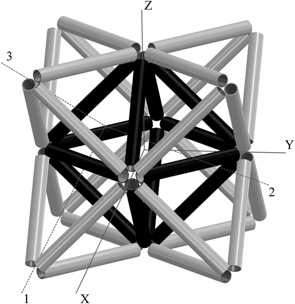
The zero expansion elements can also be used to create three-dimensional lattices. One three-dimensional lattice configuration that is known for its stiffness properties is the octet-truss lattice. The octet-truss lattice cell consists of an octahedron and eight tetrahedrons. Figure 5 depicts an isometric view of an octet-truss unit cell. The structure is stretch dominated, and thus, analogous to the two-dimensional triangular lattice is a good choice for structural stiffness. The mechanical properties of the octet-truss lattice are described in the literature.Reference Deshpande, Fleck and Ashby14 It is possible to modify the basic properties described previously and apply them to the zero thermal expansion tube elements described here. This analysis treats the element connections as pin connected, allowing joint angles to freely rotate. The relative density of a zero expansion octet-truss lattice composed of bi-material wire wrapped tubes is given by Eq. (24)
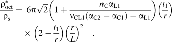 $${{{\rm{\rho }}_{{\rm{oct}}}^{\rm{*}} } \over {{\rm{\rho }}_{\rm{s}} }} = \,\,\,6{\rm{\pi }}\sqrt 2 \left( {1 + {{n_{\rm{C}} {\rm{\alpha }}_{{\rm{L1}}} } \over {{\rm{\nu }}_{{\rm{CL1}}} \left( {{\rm{\alpha }}_{{\rm{C2}}} - {\rm{\alpha }}_{{\rm{C1}}} } \right) - {\rm{\alpha }}_{{\rm{L1}}} }}} \right)\left( {{{t_1 } \over r}} \right)\left( {2 - {{t_1 } \over r}} \right)\left( {{r \over L}} \right)^2 \quad .$$
An octet-truss lattice constructed of bi-material nested tube elements. Each element is identical; the black and white colors are used to provide visual contrast between the center octahedron and surrounding tetrahedra. The two coordinate axis used in the analysis are depicted. Axis 123 is centered with respect to a surrounding tetrahedron, whereas the XYZ axis is centered with respect to the center octahedron.
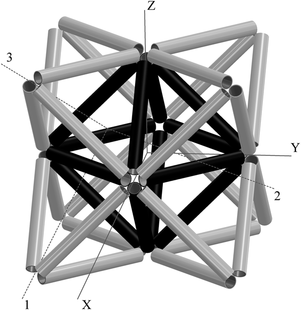
The octet-truss has different Young’s moduli in its three principle directions, but these differences are slight, so this analysis only considers the stiffest principle direction, along the 33 axis. The mechanical stiffness for a nested tube lattice can be obtained by modifying the existing Young’s moduli equations for an octet-truss lattice.Reference Deshpande, Fleck and Ashby14 This formulationReference Deshpande, Fleck and Ashby14 treats the elements as solid rods. To modify these results to the current analysis, the stiffness of the solid rod is taken as that of a tube element. This stiffness is simply a Voigt composite of material one and the void space created by the hollow section of the tube. Material two is neglected in the stiffness analysis, making this result applicable to elements where axial deformation coupling has been mitigated. The octet-truss Young’s moduli is given by Eq. (25)
 $$E_{33} = {6 \over 5}{\rm{\pi }}\sqrt 2 \left( {{r \over L}} \right)^2 \left( {{{t_1 } \over r}} \right)\left( {2 - {{t_1 } \over r}} \right)E_{{\rm{L1}}} \quad .$$
To calculate the relative stiffness for the octet-truss lattice, the same value for E s given by Eq. (22) can be used because the material composition required to achieve zero expansion remains unchanged. The solid stiffness is the same because the same volume ratio is required to achieve zero thermal expansion for both lattices.
VI. BUCKLING STRENGTH ANALYSIS—TWO-DIMENSIONAL LATTICE
In addition to the mechanical stiffness of the honeycomb, it is important to consider its strength. It is necessary to know at what point the zero CTE material will fail to carry any additional load. Creating lattice elements out of tubes can significantly increase the critical buckling load of the element and thus the overall strength of the lattice structure. Three buckling modes were considered. Each mode’s critical lattice stress was computed in terms of lattice parameters. Euler buckling, symmetric buckling, and asymmetric buckling modes were analyzed as described by Timoshenko and Gere.Reference Timoshenko and Gere15
The critical stress applied to the lattice and acting on a surface area equal to twice the radius times the height of an equilateral triangle, which will cause buckling is calculated for each of the three buckling modes. The tube buckling stress is then normalized by the critical buckling stress of an identical lattice, if the cross-sectional area was distributed as a solid cylindrical element. Assumptions made for this analysis include that the tubes are pin connected at lattice nodes, allowing joints to freely rotate, the lower thermal expansion material is isotropic, and the higher thermal expansion material does not participate structurally. It should be noted that this strength analysis accounts for thin- and thick-walled tubes, where the thermal expansion analysis and consequently the relative density of zero thermal expansion tubular lattices require thin-walled tubes. Equations (26)–(28) provide normalized critical stresses for Euler, symmetric, and asymmetric buckling modes, respectively
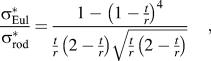 $${{{\rm{\sigma }}_{{\rm{Eul}}}^{\rm{*}} } \over {{\rm{\sigma }}_{{\rm{rod}}}^{\rm{*}} }} = {{1 - \left( {1 - {t \over r}} \right)^4 } \over {{t \over r}\left( {2 - {t \over r}} \right)\sqrt {{t \over r}\left( {2 - {t \over r}} \right)} }}\quad ,$$
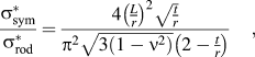 $${{{\rm{\sigma }}_{{\rm{sym}}}^{\rm{*}} } \over {{\rm{\sigma }}_{{\rm{rod}}}^{\rm{*}} }} = {{4\left( {{L \over r}} \right)^2 \sqrt {{t \over r}} } \over {{\rm{\pi }}^2 \sqrt {3\left( {1 - {\rm{\nu }}^2 } \right)} \left( {2 - {t \over r}} \right)}}\quad ,$$
 $${{{\rm{\sigma }}_{{\rm{asym}}}^{\rm{*}} } \over {{\rm{\sigma }}_{{\rm{rod}}}^{\rm{*}} }} = {{12\left( {{L \over r}} \right)^2 \left( {{t \over r}} \right)^2 } \over {5{\rm{\pi }}^2 \left( {1 - {\rm{\nu }}^2 } \right)\sqrt {{t \over r}\left( {2 - {t \over r}} \right)} }}\left( {{2 \over 3}\left( {{L \over r}} \right)^2 + 1 - {\rm{\nu }}} \right)\quad .$$
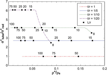
The length, radius, and wall thickness of material one are given by L, r, and t, respectively. The overall critical stress of the lattice is considered to be the smallest of the three buckling modes described by Eqs. (26)–(28). Figure 6 plots the critical buckling stress of zero expansion tube lattices, normalized by a solid rod area configuration versus the relative density determined by Eq. (23). The curves are generated by specifying a thickness ratio (t/r) and then varying the aspect ratio (L/r). All three critical stress values are calculated, although only the minimum value buckling mode is plotted. All curves shown are for Invar tubes wrapped with steel wire and use a Poisson’s ratio of 0.28. Euler critical loads are indicated by horizontal curves and are dominant for slender elements with large L/r ratios. For tubes with thin walls and smaller aspect ratios, symmetric buckling becomes the critical mode. For even thinner walls and yet smaller aspect ratios, asymmetric buckling becomes the critical mode. For the geometries chosen, asymmetric buckling does not become the critical mode. Distributing the area of the elements as a thin-walled tube provides a substantial increase in strength, provided that Euler buckling is the critical mode. For higher density lattices with lower aspect ratios, it may be desirable to utilize a more solid area distribution (thicker wall tubes).
The critical tube buckling stress normalized by the critical stress of an identical lattice with the cross-sectional area redistributed as a solid rod (t/r = 1).

VII. BUCKLING STRENGTH—THREE-DIMENSIONAL LATTICE
The octet-truss lattice has multiple collapse modes. These modes are described in depth by prior studies.Reference Deshpande, Fleck and Ashby14 This analysis only studies the elastic buckling mode for the geometry of zero expansion bi-material tube elements. To modify the relationships described in the literature,Reference Deshpande, Fleck and Ashby14 the formula for the solid rod octet-truss lattice is rewritten in terms of the area moment of inertia and material Young’s modulus, as opposed to lattice geometry parameters and material yield strength. Equation (29) provides the modified relationship for Euler buckling, in the ZZ direction in terms of area moment of inertia (I) and Young’s modulus (E)
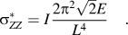 $${\rm{\sigma }}_{ZZ}^* = I{{2{\rm{\pi }}^2 \sqrt 2 E} \over {L^4 }}\quad .$$
From Eq. (29), it can be seen that the critical stress does not depend on cross-sectional area properties other than the area moment of inertia. This differs from the two-dimensional lattice, where the area to which the critical stress was applied depended on the radius of the constituent elements. By replacing the area moment of inertia in Eq. (29) with the lattice parameters for a tubular geometry, Eq. (30) can be written
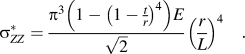 $${\rm{\sigma }}_{ZZ}^* = {{{\rm{\pi }}^3 \left( {1 - \left( {1 - {t \over r}} \right)^4 } \right)E} \over {\sqrt 2 }}\left( {{r \over L}} \right)^4 \quad .$$
It is noted that for a thickness over radius ratio of one, representing solid rod geometry, Eq. (30) will reduce to the original, unmodified Equation.Reference Deshpande, Fleck and Ashby14 To quantify the expected improvement of elastic buckling strength, Eq. (30) is normalized by the critical stress of a lattice composed of solid rod elements of equal cross-sectional area. This also is just simply the ratio of the area moments of inertia for the two geometries. Equation (31) provides the general ratio in terms of lattice parameters
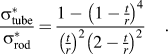 $${{{\rm{\sigma }}_{{\rm{tube}}}^{\rm{*}} } \over {{\rm{\sigma }}_{{\rm{rod}}}^{\rm{*}} }} = {{1 - \left( {1 - {t \over r}} \right)^4 } \over {\left( {{t \over r}} \right)^2 \left( {2 - {t \over r}} \right)^2 }}\quad .$$
Specifying a tube-shaped geometry as opposed to a solid rod element provides a considerable resistance to Euler buckling, e.g., tubes with t/r = 0.1 give a strength enhancement of a factor of about 9.5 compared with solid rods. As the critical Euler buckling stress of the lattice increases, the structure becomes more susceptible to other modes of failure, some of which are described for solid rod geometries.Reference Deshpande, Fleck and Ashby14
VIII. CONCLUSION
The thermal expansion coefficient of a porous material can be tailored as desired. Specifically stiff zero-expansion lattices are designed using Poisson contraction in nested tubular ribs. This technique requires two materials with differing thermal expansion. If both materials have positive expansion, interface stress must be controlled by providing a slip or via a ring or wire wrap geometry for one material. Graphite-epoxy tubes wrapped with Kevlar-epoxy provide the best relative stiffness for a given relative density. Use of Invar wrapped with aluminum provides a nearly identical relative stiffness to density ratio. The advantage is that Invar and aluminum are fairly commonly used structural materials and are advantageous from a manufacturing perspective. In addition to providing stiff zero expansion lattices, utilizing a tubular rib geometry has the benefit of increasing the materials resistance to buckling, thus substantially increasing the materials strength. It is also possible, using the methods presented here, to find other more desirable material pairs that can be tailored to obtain zero thermal expansion.
ACKNOWLEDGMENT
Support from DARPA-LLNL under the aegis of Dr. Judah Goldwasser is gratefully acknowledged.