1. Introduction
Based on kinematic architecture, industrial robots can be categorized into three primary groups: serial, parallel, and hybrid manipulators. While serial manipulators have open-loop kinematic chains including a series of links connected to each other by actuated joints, parallel manipulators have closed-loop kinematic chains that contain more than one serial kinematic chain connected to a moving platform. Hybrid manipulators are combinations of serial and parallel manipulators. Independent of the type of robot, robots achieving high accelerations can encounter deviations from the planned path. This deviation is related to the robot’s repeatability, positioning accuracy, and stiffness properties.
According to [Reference Patel and George1], parallel robots have more advantages than serial robots in terms of stiffness, high load/weight ratios, and low inertia. Additionally, parallel robots have superior positioning accuracy since joint errors are shared rather than accumulating as they do in serial robots [Reference Briot and Bonev2]. Furthermore, there are over-constrained robots that do not satisfy the Grübler–Kutzbach mobility formula [Reference Waldron3] and have more DoF than calculated by this formula. In other words, they are robot manipulators including redundant constraints. As a result of these redundant constraints causing internal stresses that decrease the joint clearances, over-constrained robots display better stiffness characteristics, and repeatability performance relative to the normal-constrained robots that are kinematically equivalent [Reference Paksoy4]. The effect of the gravity and internal stresses on the positioning accuracy can be compensated via the kinematic calibration processes described in [Reference Kiper, Dede, Uzunoğlu and Mastar5] using standards for testing such as VDI/DGQ 3441 – Statistical Testing of the Operational and Positional Accuracy of Machine Tools; Basis.
When the aforementioned considerations to improve the trajectory-tracking performance of high-acceleration robots are addressed during the design and calibration processes, the effect of the compliant behavior of the robot gains precedence. Enhancing the trajectory-tracking accuracy of robots has been well investigated in the literature. For example; (i) using nonlinear control theory such as model predictive control (MPC) as in [Reference Faulwasser, Weber, Zometa and Findeisen6], (ii) a combination of deep neural networks (NNs) and MPC, in [Reference Nubert, Köhler, Berenz, Allgöwer and Trimpe7], (iii) compliant robot control [Reference Dong, Ren, Wu and Chen8], and (iv) vibration control by input shaping [Reference Singhose and Chuang9]. This paper is focused on addressing this issue by considering the stiffness properties. We aim to enhance the trajectory-tracking of robots operating at high accelerations by predicting their compliance characteristics and implementing these estimations in a trajectory updating algorithm.
In the literature, there are numerical, analytical, semi-analytical, and experimental analysis techniques for modeling the stiffness characteristics of the robot. As a numerical analysis method, finite element analysis (FEA) is the most precise one to calculate the stiffness matrix of a mechanism but has a high computational cost. For this reason, it is not suitable for real-time trajectory correction operations and is generally used for verification and optimization of model parameters [Reference Klimchik, Pashkevich and Chablat10]. Analytical stiffness modeling methods that are commonly used in the literature are (i) Virtual Joint Method (VJM) and (ii) Matrix Structural Analysis (MSA). VJM is the simplest and fastest method to calculate the stiffness model of the robot where the rigid-body kinematic model of the robot is extended by adding virtual joints at the end of links, joints, and actuators in order to take into account their elastic deformations. The idea of the VJM has been originated from Salisbury and Craig [Reference Salisbury and Craig11]. Then, it is extended for parallel robots [Reference Gosselin12] and over-constrained robots [Reference Pashkevich, Chablat and Wenger13]. A recent study outlined in [Reference Görgülü, Carbone and Dede14] explains how VJM can be used to calculate the stiffness model in a time-efficient manner, resulting in a 2 kHz computation rate. MSA results in better modeling precision, but longer computation time when compared to VJM. The details of stiffness modeling with MSA are presented in [Reference Klimchik, Pashkevich and Chablat15]. Analytical models require a parameter identification procedure and some examples can be given as follows: (i) a VJM-based stiffness model of the robot can be constructed with unknown model parameters and then, these unknown parameters can be identified by using the simulation and/or experimental results [Reference Klimchik, Furet, Caro and Pashkevich16]. (ii) Deep NNs or genetic algorithm-based models can be developed to identify the parameters of the defined models [Reference Chen, Zhang and Sun17]. To obtain the stiffness properties of a robot using experimental methods, two elements are required. These elements are given as follows: (i) the source of external forcing and (ii) a measurement method for the compliant displacements. Examples of the test setups for investigating the stiffness behavior of the mechanisms: (i) in [Reference Ceccarelli and Carbone18], a combination of linear variable differential transformer (LVDT) sensors and a different set of calibrated masses, (ii) in [Reference Taner and Dede19], a camera-based computer vision system and calibrated masses, (iii) in [Reference Görgülü, Dede and Carbone20], a laser range sensor and a pulley-guided system, and (iv) in [Reference Alici and Shirinzadeh21], a laser tracker and pulley-cable system that includes a force sensor are used as the compliant displacement measurement system and force exerting system, respectively.
A trajectory correction technique that adjusts the motion input by feeding back the compliant displacements of the end-effector has been developed for robotic-based machining operations. These compliant displacements are calculated by using a nonlinear stiffness model and a reduced elastodynamic model of the robot. Physical contact forces are measured with a force/torque sensor at the interaction point, and the experiments are executed by KUKA KR270 serial robot to show that the proposed algorithm works [Reference Klimchik, Bondarenko, Pashkevich, Briot and Furet22]. In another work, the idea of using the Lagrangian dynamics of the robot system is proposed for the calculation of the compliant displacements related to the forces/moments measured by a sensor at the end-effector. Also, they proposed using the Quantum Monte Carlo technique, after the compliant displacements are calculated, in order to minimize the action of motion that is needed for the correction of trajectory [Reference Dautov and Klimchik23]. However, using a force/torque sensor generally calls for the use of a low-pass filter and since a numerical method is implemented, this procedure has a high computational cost for online correction of the trajectory. In [Reference Olabi, Damak, Bearee, Gibaru and Leleu24], the stiffness model of each joint of a 6-DoF serial robot is identified by performing experiments. Then, this information is used in an offline trajectory correction procedure. The validation experiments are conducted by tracking a smooth spiral path at low speeds and accelerations in order to create a quasi-static condition. In this way, all dynamic effects on the compliant behavior of the robot are neglected.
In our case, the physical interaction of the robot with its environment is not considered as it was in [Reference Klimchik, Bondarenko, Pashkevich, Briot and Furet22, Reference Dautov and Klimchik23]. The main reason for the compliant displacements is the dynamic forcing due to the high-acceleration operation (up to 5 g) of the robot. To calculate dynamic forces in terms of D’Alembert’s forces, an accelerometer can be used that is placed on the moving platform by neglecting the contributions of the links’ inertial properties, or measured joint motion can be mapped to end-effector motion via rigid-body kinematics by undermining changes in kinematic parameters due to compliant displacements of the links and joints. Generally, sensory feedback from an accelerometer contains noise that must be filtered out with a low-pass filter in order to get accurate measurements. This filtering process causes a decrease in the bandwidth and the operation speed. Since any sensor feedback comes with the drawback of computation time, it may conflict with the need for the high-frequency trajectory correction process of the high-acceleration robots.
Therefore, as novelties of this study: (i) it is proposed to correct the trajectory by considering the compliant displacements which are computed using D’Alembert’s forces that are calculated based on desired motion inputs, and (ii) it is proposed that the compliance information obtained from the stiffness tests performed in the static condition can be used in this trajectory correction process. Here, the static condition tests are the experiments carried out at various fixed (actuators are locked) configurations of the robot throughout its workspace. In these tests, the compliant displacements of the tip point of the end-effector are measured with respect to the applied external forcing that simulates the D’Alembert’s forces occurring during the high-acceleration dynamic operation of the robot.
The proposed trajectory correction idea is implemented on an over-constrained and a normal-constrained parallel robot that have the same kinematic equations. In this way, it is aimed to show that the proposed algorithm is efficient in both types of mechanisms. Since D’Alembert forces act on the CoM of a rigid body, the effect of the relocation of the CoM of the end-effector on the trajectory correction algorithm is investigated in this paper.
In Section 2, compliance modeling of robots with high acceleration and high payloads is formulated by assuming dominant D’Alembert’s forces occurring at the end-effector. In Section 3, the proposed generalized methodology for enhancing trajectory-tracking accuracy is explained, and the steps for the implementation of the trajectory correction algorithm are presented. In Section 4, the implementation of the proposed methodology for a case study is given by formulating the compliance model of the mechanism. In Section 5, test setup, procedure, and evaluation methodology for trajectory-tracking performance for the case study are presented. In Section 6, test results are evaluated and interpreted by illustrating the results with plots and graphs. In Section 7, significance of the paper is stated. In Section 8, the efficiency of the proposed algorithm is discussed, the implementation insights are given, and future studies are addressed.
2. Compliance modeling for lightweight robots with high payload and no physical contact
In theory, the end-effector position vector of the mechanism derived from the rigid-body forward kinematics maps the joint space positions to the end-effector position (
 $\bar{\kappa }_{FW}$
). However, in practice, the end-effector’s position depends on some parameters in addition to the forward kinematics which assumes rigid links. The dominant parameters that affect the accuracy of the mechanism can be represented by mainly three parameters which are positional change because of the gravity (
 $\bar{\kappa }_G$
), positional change due to the internal stresses that occur due to the assembly of the mechanism (
 $\bar{\kappa }_I$
), and joint clearances (
 $\bar{\kappa }_J$
). If the mechanism is subjected to an external forcing vector
 $\bar{F}_{ext}$
that contains both external forces and moments, an extra term related to the compliance model
 $\boldsymbol{\hat{C}}$
of the mechanism plays an important role while determining the end-effector location of the mechanism. As a result of that, the end-effector location of the mechanism
 $\bar{\kappa }_{E}$
can be expressed as follows:
 \begin{align} \bar{\kappa }_{E}=\bar{\kappa }_{FW}+\bar{\kappa }_G+\bar{\kappa }_I+\bar{\kappa }_J+ \boldsymbol{\hat{C}}\bar{F}_{ext} \end{align}
Position level forward kinematics (
 $\bar{\kappa }_{FW}$
) of the mechanism can be calculated via rigid-body assumption when essential kinematic parameters of the robot are known. The effect of the gravity (
 $\bar{\kappa }_G$
) and internal stresses (
 $\bar{\kappa }_I$
) can be calculated by a kinematic calibration technique as aforementioned. As the nature of the over-constrained kinematic structure, the effect of joint clearances reduces the uncertainties to a level that these effects can be neglected. As a result of that,
 $\Delta \bar{\kappa }_{E}$
amount of change in the end-effector position is given as follows:
 \begin{align} \Delta \bar{\kappa }_{E}=\boldsymbol{\hat{C}}\bar{F}_{ext}=\bar{\kappa }_{E}-\bar{\kappa }_{cal}-\bar{\kappa }_{neg} \end{align}
where the term
 $\boldsymbol{\hat{C}}\bar{F}_{ext}$
contains the compliant displacements of the mechanism with respect to the subjected external forcing, the terms
 $\bar{\kappa }_{FW}$
,
 $\bar{\kappa }_G$
, and
 $\bar{\kappa }_I$
are compiled in a term
 $\bar{\kappa }_{cal}$
, and the term
 $\bar{\kappa }_J$
is represented as a neglected parameter
 $\bar{\kappa }_{neg}$
. Up to now, the equations given above are valid for static conditions. Under dynamic conditions, there will be no external forcing when there is no physical interaction with the environment. However, lightweight mechanisms that operate at high accelerations with a relatively large end-effector mass will result in compliant displacements because of the dynamic forces.
Since the end-effector of the lightweight robot carries a high payload, the inertia of the links can be neglected and only the inertia of the end-effector can be considered.
Adopting these assumptions, a lightweight robot with a relatively large payload can be simplified to a mass
 $m_{E}$
and an inertia matrix
 $\hat{J}_{E}$
calculated at the CoM of the end-effector. It is assumed that the external forcing
 $\bar{F}_{ext}$
only acts at and about the CoM of the end-effector, and therefore they are abbreviated as
 $\bar{F}_{E}$
that contains the net forces
 $\bar{F}_{net}$
and net moments
 $\bar{M}_{net}$
. When a lightweight robot that can control the position and orientation of the end-effector is considered, equations of motion are formulated as follows:
 \begin{align} \bar{F}_{net}&=m_{E}\bar{a}_{E} \nonumber \\[3pt] \bar{M}_{net}&=\hat{J}_{E}\bar{\alpha }_{E}+\tilde{\omega }_{E}\hat{J}_{E}\bar{\omega }_{E} \end{align}
where the end-effector’s motion is defined with an angular velocity vector of
 $\bar{\omega }_{E}$
, a linear acceleration vector
 $\bar{a}_{E}$
, an angular acceleration vector of
 $\bar{\alpha }_{E}$
and
 $\tilde{\omega }_{E}$
cross-product matrix derived from
 $\bar{\omega }_{E}$
. The matrix equation in Equation 3 for Newton’s equation is obtained by using the inertial frame resolution and Euler’s equation is obtained by using the body-fixed frame resolution to facilitate the representation. Let’s consider a robot that can only control the position of the end-effector. In Equation 4, by using D’Alembert’s principle of inertial forces, an accelerating body can be analyzed as a system in static equilibrium subjected to inertial forces (D’Alembert’s forces)
 $\bar{F}_{D}$
. For clarity, D’Alembert’s moments are not considered in this case. If there is a case where the end-effector has both translational and rotational motion, then both D’Alembert’s forces and moments can be taken into consideration:
 \begin{align} \bar{F}_{net}+ \bar{F}_{D}=0 \end{align}
D’Alembert’s forces (
 $\bar{F}_{D}$
) acting at the CoM location of the end-effector can be represented by the following equation:
 \begin{align} \bar{F}_{D}=-m_{E}\bar{a}_{E} \end{align}
where the D’Alembert’s forces are equals to
 $-\bar{F}_{net}$
. Therefore, the compliant displacements of the CoM point of the end-effector
 $\Delta \bar{\kappa }_{E}$
can be assumed to be the result of D’Alembert’s forces acting on this point. By considering these D’Alembert’s forces as external forces for lightweight robots with large-end-effector mass operating at high-acceleration motion, Equation 2 can be updated as follows:
 \begin{align} \Delta \bar{\kappa }_{E}=\boldsymbol{\hat{C}}\bar{F}_{D} \end{align}
This formulation based on the aforementioned assumption is a novel approach presented in this paper.
3. Proposed generalized methodology for enhancing trajectory-tracking accuracy
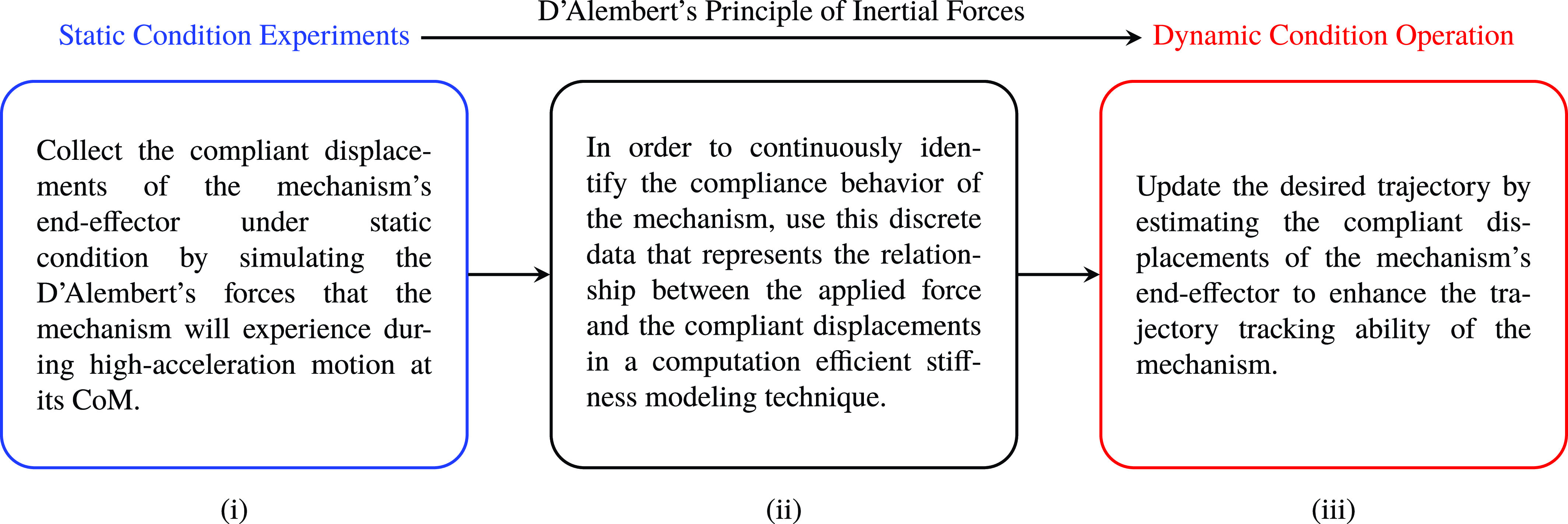
Building on the idea of using D’Alembert’s force as external forces applied on the end-effector for calculating compliant displacements of a lightweight robot with a large payload, Figure 1 indicates the necessary steps in developing a trajectory correction algorithm. Here, the essential notion is the assumption of D’Alembert’s forces as external forces applied in a static condition. Therefore, a compliance model of the robot can be obtained assuming static conditions. The updates on the trajectory can be issued to compensate for the compliant displacements that are calculated with this compliance model using D’Alembert’s forces. The steps of this algorithm are summarized as follows: (i) discrete data collection that represents the relationship between applied force and compliant displacement of the end-effector, (ii) a mathematical tool to identify the compliance characteristics of the end-effector in the continuous domain, and (iii) trajectory update procedure by using the compliant displacement information. These steps are explained in detail in Sections 3.1, 3.2, and 3.3.
Methodology for enhancing trajectory-tracking accuracy of high-acceleration robots.

3.1 Compliant displacement acquisition in static conditions
The compliance behavior of the mechanism can be identified by using a numerical analysis method such as FEA. In some special mechanical designs of the links or joints, mechanisms may include materials that are not possible to be modeled perfectly. Therefore, in general, experimental methodology becomes compulsory to model the compliance characteristics of the mechanism more accurately.
To determine the compliance matrix of the mechanism
 $\boldsymbol{\hat{C}}$
in static condition by using an experimental technique, we generally need a setup that consists of two elements; one of them is the displacement measurement sensor to measure the compliant displacements of end-effector
 $\Delta \bar{\kappa }_{E}$
and the other one is a system for exerting different set of forces
 $\bar{F}_{E}$
at the CoM of the end-effector. The range of the external forces
 $\bar{F}_{E}$
to be applied in such an experimental setup is determined based on D’Alembert’s forces
 $\bar{F}_{D}$
calculated with respect to the desired accelerations of the end-effector. As a consequence of applying these forces to the CoM of the end-effector in a designated workspace, a set of discrete data that includes the information of the applied force
 $\bar{F}_{E}$
and compliant displacements
 $\Delta \bar{\kappa }_{E}$
related to these applied forces are gathered.
3.2 Identification of the compliance model from experimental results
In this step, discrete data relating the applied force
 $\bar{F}_{E}$
to the compliant displacements of the robot’s end-effector
 $\Delta \bar{\kappa }_{E}$
gathered in Section 3.1 is used with a mathematical tool or a function to define the compliance behavior of the robot. The tool or the function to be used can be determined by investigating the complexity of the relationship between the applied force and compliant displacements. This relationship can be a rather simple linear relationship or may exhibit highly nonlinear characteristics. By considering the data and the dynamics of the system a simple polynomial fit or a complex deep neural net (NN) can be used to identify the relationship throughout the robot’s workspace. Also, interpolation techniques such as bilinear and bicubic interpolations can be used to extend the continuous relationship throughout the robot’s workspace. Although the bicubic interpolation set smoother relationships with respect to the bilinear interpolation, it is relatively computationally inefficient, complex, and requires more data.
3.3 Trajectory update procedure
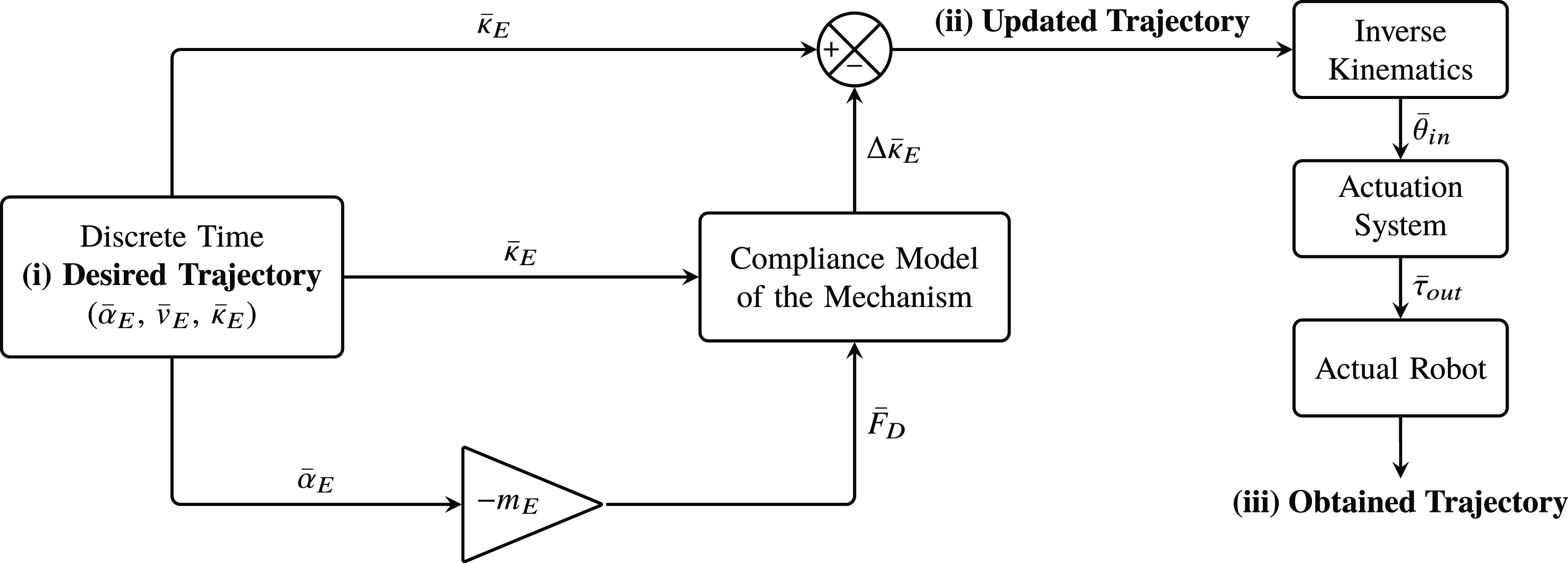
This section explains how the robot’s compliance model can be utilized to increase trajectory-tracking accuracy. In Figure 2, the flowchart diagram for updating the trajectory can be seen. The ”Desired Trajectory” for the end-effector is determined by using an acceleration profile
 $\bar{\alpha }_{E}$
in the motion planning step. As a result of the motion planning, velocity profile
 $\bar{v}_{E}$
and end-effector position
 $\bar{\kappa }_{E}$
are available. D’Alembert’s forces are calculated using this
 $\bar{\alpha }_{E}$
. In practice, the actual end-effector accelerations will be different than
 $\bar{\alpha }_{E}$
because of the compliance of the mechanism. The algorithm accounts for the first and highest-amplitude peaks of the compliant displacements which are calculated at a high frequency. Therefore, this high-frequency computation of compliant displacements imposes an iteration procedure to capture the vibrational behavior of the system. If the trajectory correction algorithm works at high frequencies and the actuators have sufficient performance for the requested motion, then the ”Obtained Trajectory” of the end-effector will be close to the ”Desired Trajectory.” It should be noted that the assumption for neglecting the influence of the links must hold to calculate the inertial forces used in this algorithm. This condition is discussed in detail in Section 4.1 on a case study.
After estimating D’Alembert’s forces, these forces and end-effector position are fed to the compliance model of the mechanism. As a result of that, the end-effector’s compliant displacements are predicted and the trajectory is updated. The ”Updated Trajectory” is issued as input in the inverse kinematics equations of the mechanism and the corresponding joint angles
 $\bar{\theta }_{in}$
are calculated. These joint angles are transmitted to the actuation systems that drive the mechanism. As a result of the force/torque output of the actuation system
 $\bar{\tau }_{out}$
, the manipulator moves and the end-effector follows a trajectory which is noted as ”Obtained Trajectory” in Figure 2.
Flowchart diagram for trajectory updating process.

4. Case study: 2-DoF over-constrained and normal-constrained mechanism
In this section, 2-DoF planar over-constrained mechanism and normal-constrained mechanism are mentioned by illustrating kinematic sketches of mechanisms, references for the calculation of rigid-body kinematics are given, and a solid model of the over-constrained mechanism is given by presenting its components and mass properties. Then, the general methodology to enhance the trajectory-tracking accuracy is explained for our case related to 6R over- and normal-constrained mechanisms. Finally, the necessary calculations for compliance modeling are given.
4.1 2-DoF planar over-constrained mechanism and normal-constrained mechanism
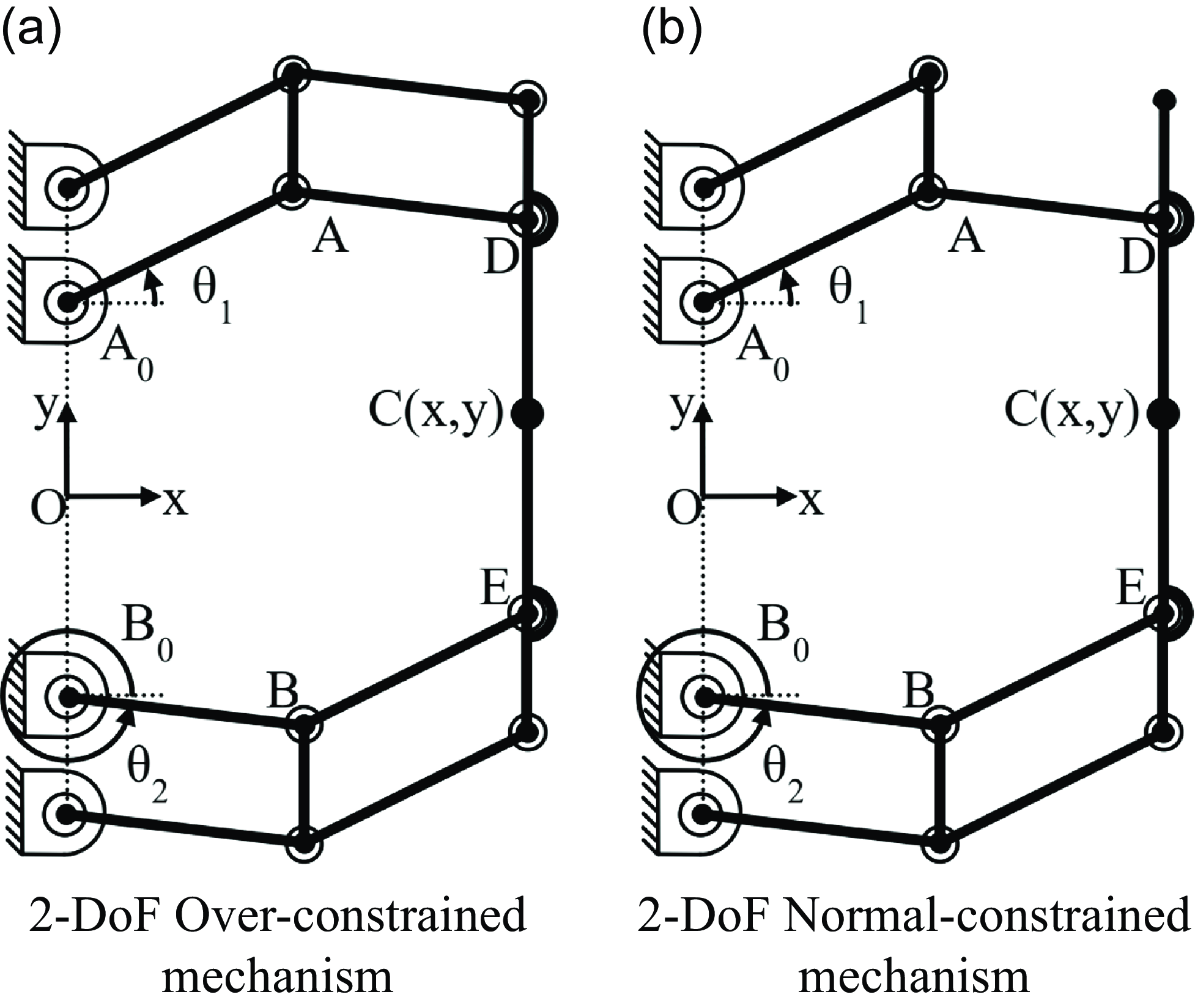
Figure 3 shows kinematic sketches of two robot manipulators that are used in the case study. In Figure 3a, there is a 2-DoF over-constrained mechanism. For the over-constrained mechanism, the calculated DoF from the Grübler–Kutzbach mobility formula is 1, while in practice, this mechanism has a 2-DoF translational motion on xy plane. In Figure 3b, a 2-DoF normal-constrained mechanism is configured by removing one of the links of the parallelograms that constrains the end-effector’s rotation. For this mechanism, both the Grübler–Kutzbach mobility formula outcome and practical operation indicate 2-DoF translational motion.
Robot manipulators for the case study.

Analytical inverse kinematics solution is not possible for the 2-DoF over-constrained mechanism with arbitrary link lengths and that is its major disadvantage. Considering the positioning task of Point C, the mechanisms presented in Figures 3a and 3b are kinematically equivalent when the corresponding link lengths are equal to each other. Therefore, the kinematic calculations of the 2-DoF over-constrained and normal-constrained mechanisms can be executed by using the hidden robot concept. A description of this kinematic equivalence and calibration via the hidden robot concept is presented in [Reference Kiper, Dede, Uzunoğlu and Mastar5] and rigid-body kinematics are presented in [Reference Özkahya25]. To give an insight related to the kinematic model of the robots, the link lengths of the robot
 $\|\mathrm{\mathbf{A_0A}}\|$
,
 $|\mathrm{\mathbf{AD}}|$
,
 $|\mathrm{\mathbf{B_0B}}|$
,
 $|\mathrm{\mathbf{BE}}|$
and the links parallel to these set of links are all designed to be 150 mm. The dimensions of
 $|\mathrm{\mathbf{A_0 O}}|$
,
 $|\mathrm{\mathbf{B_0 O}}|$
,
 $|\mathrm{\mathbf{DC}}|$
, and
 $|\mathrm{\mathbf{EC}}|$
are set as 90 mm. Since these types of constrained mechanisms shows higher repeatability and load capacity, it can be used in applications where the precise operation is needed in a relatively small workspace (150 mm x 100 mm) and/or high-acceleration capacity is required. In this paper, the investigations are carried out for the path following applications that require high acceleration and precision at the same time. One of the examples of this type of an application is laser cutting operations. In [Reference Uzunoğlu, Tatlicioğlu and Dede26–Reference Leibinger, Rauser and Zeygerman30], similar mechanisms are used as the micro-robot in macro-micro manipulation. In these works, although a micro-manipulator is used, there is no information on the use of a trajectory update algorithm to enhance their precision during high-acceleration motion profiles.
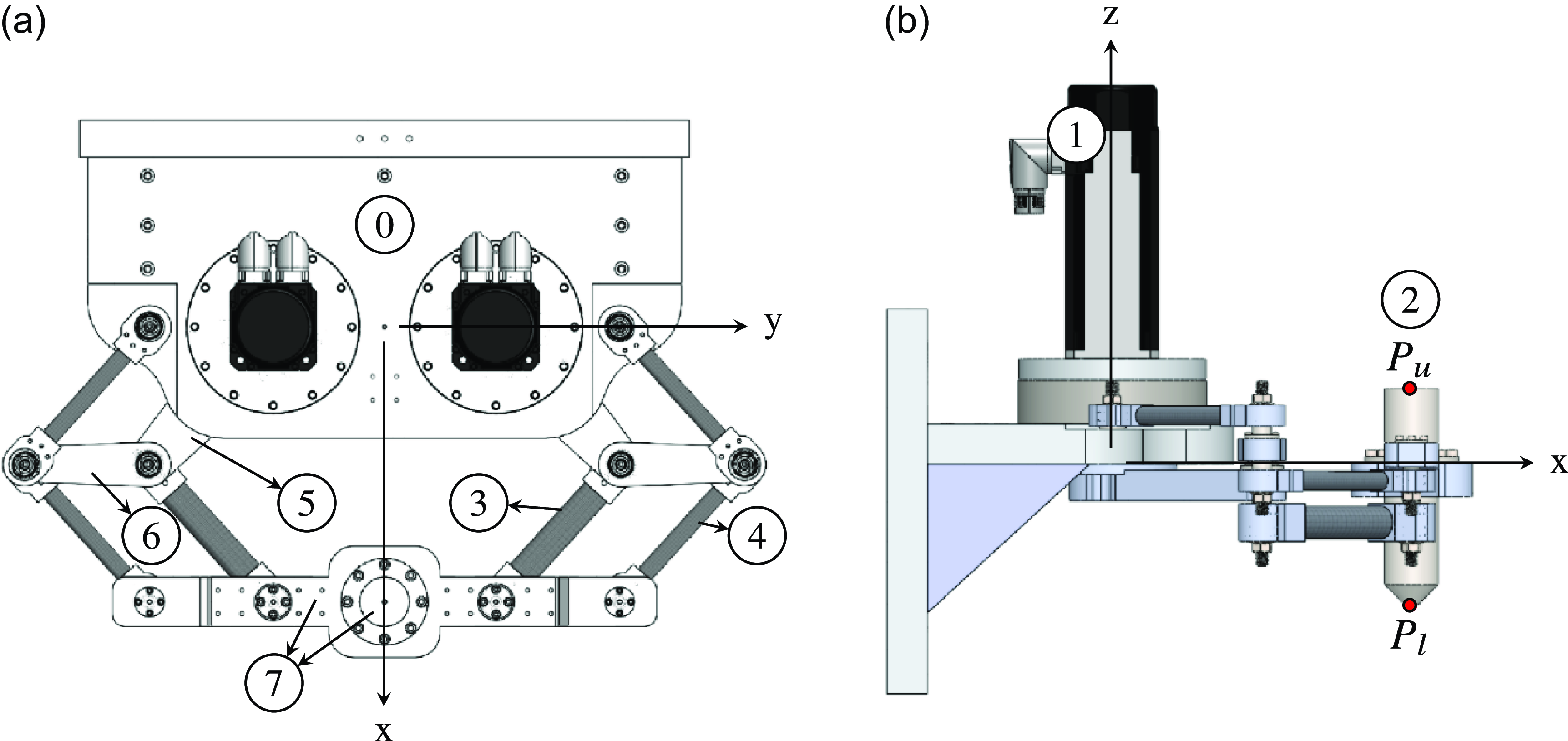
a) Top view of the 3D model, b) right-view of the 3D model; 0: base platform, 1: motor and reducers, 2: replica of the laser head end-effector (
 $P_u$
and
 $P_l$
are upper and lower measurement points for the static condition tests, respectively.), 3: thick distal link (219.4 gr), 4: thin link (123.6 gr), 5: actuated links, 6: intermediate platforms (251.2 gr), 7: moving platform including end-effector (3.6 kg) [Reference Paksoy, Dede and Kiper31].

In Figure 4, the solid model of the 2-DoF planar over-constrained mechanism is shown. The top and side view of the robot are illustrated in order to show the design of the mechanism along with its important components. To minimize the energy consumption of the manipulator that operates at high accelerations of up to 5 g, links composed of carbon fiber tubes and aluminum (links 3 and 4) are selected in the design process. The aluminum and carbon fiber parts of these links are connected to each other with an adhesion material (in general, a type of glue). The aluminum part is used for the kinematic pair structure to compose revolute joints with a connected link. The actuated links (link 5), the intermediate platforms (link 6), and the moving platform (link 7) are manufactured from aluminum for improving the relative rigidity of these components with respect to the others. Part 2 identifies a replica of the end-effector, and it is rigidly connected to the moving platform. The abbreviation of CoM denotes the center of mass of both of these components. Part 1 denotes the two servomotors with gearheads used as the actuation system that is located at the base platform.
Since the actuated links are connected to a base platform and have relatively higher rigidity with respect to the other links, the mass of the actuated links is not reported, and they are assumed as rigid bodies. For the thick distal links and all thin links, the aluminum part composes 85% and 90% of the total mass of the links, respectively. That means, these links can be considered as a lumped mass system where the masses are lumped around the revolute joints located approximately at the center of the aluminum parts. Therefore, half of the masses of the two thick and two thin links which are connected to the moving platform are considered as a part of the moving platform which results in a 3.6 kg of total moving platform mass. Half of the masses of the two thin links located near to the base platform can be neglected since these links are connected to the base platform via the revolute joint structure, and thus, have negligible motion during the operation.
As a result of the aforementioned assumptions, the ratio of the total mass of the links to the mass of the moving platform is approximately 0.26. Furthermore, the acceleration levels of the links are roughly half of the platform’s acceleration. Therefore, the ratio for D’Alembert’s forces resulting from the link masses to the moving platform mass is approximately 0.13. Accordingly, neglecting the inertial forces of the links can be concluded as a reasonable assumption for our case. Additionally, the mass of the moving platform (3.6 kg) is a tunable parameter that can be adjusted during the implementation phase. Consequently, it should be noted that there is a trade-off between the accurate estimation of D’Alembert’s forces and the computation time of the trajectory correction algorithm. By accepting a minimal error in the calculation of D’Alembert’s forces, the aim is to show that the proposed methodology can be implemented in a high-frequency trajectory correction algorithm.
4.2 Implementation of the methodology for the specific case study
In this section, the implementation of the methodology for enhancing trajectory-tracking accuracy given in Section 3 is presented for our case study.
4.2.1. Compliant displacement acquisition in static conditions
In our case, an experimental methodology to acquire the compliant displacements of the mechanisms is preferred. The reasons to choose the compliance modeling of the mechanism by an experimental method are given as follows: (i) the aluminum and carbon fiber tubes can be analytically modeled, but the effect of the glue between the aluminum and carbon composite tube is hard to represent because the mechanical properties of the glue and the imperfections in its application are not known, (ii) even though the stiffness characteristics of the links are determined, due to the internal stresses that occur during the assembly, mechanisms can show different compliance characteristics at different locations of their workspace. These can only be revealed when the whole mechanism is tested experimentally for compliance modeling. Detailed manufacturing and assembly processes of the mechanisms are given in Section 4.1 and also can be found in [Reference Özkahya25].
To carry out the experiments, a portable coordinate measurement system Faro Prime Measuring Arm 1.2 is used to measure the compliant displacement of the end-effector, and a pulley-guided system with calibrated masses is used to exert forces at the CoM of the end-effector to simulate the D’Alembert’s forces. The 2-DoF over-constrained and normal-constrained mechanisms operate with up to 5 g accelerations and carry a total payload of 3.6 kg. Accordingly, the external forces are applied in x- and y-directions at uniformly spaced 15 separate end-effector locations by gradually increasing the applied forces with increments of 5 kgf (
 $\approx$
49.05 N) load up to 25 kgf (
 $\approx$
245.25 N) covering the range of possible D’Alembert’s forces during the operation. After each increment of the applied forces, the coordinates of the two specified points (
 $P_u$
and
 $P_l$
in Figure 4) on the end-effector are measured to derive information about both translational and angular compliant displacements of the end-effector. Since there are two measurement points on the end-effector, a vector between these measurement points can be drawn. Based on this vector, compliant displacement of any point along the laser beam axis (specific interest for this work is the point where this axis intersects the plane of cut). The detailed information about the compliant displacement acquisition in static conditions for our case is explained thoroughly in [Reference Paksoy, Dede and Kiper31].
4.2.2. Identification of the compliance model from experimental results
After the complaint displacements of the mechanisms are acquired, it is observed that at each fixed configuration of the robot, there is an almost linear relationship between the varying applied forces and the subsequent compliant displacements of the robot. Therefore, we assigned a first-order polynomial to each fixed configuration to define a continuous relationship between the applied force and compliant displacements at that configuration. After that, the bilinear interpolation technique is implemented among the fixed configurations to estimate the compliant displacements for the whole workspace.
4.2.3. Trajectory update procedure
The “Desired Trajectory” for the end-effector is determined by using a trapezoidal acceleration profile
 $\bar{\alpha }_{E}$
in the motion planning step by limiting velocity, acceleration, and jerk profiles. The update frequency of
 $\bar \theta _{in}$
sent to the servo-system is chosen as 2 kHz to operate the mechanism close to the rigid-body kinematics by applying a fast trajectory correction algorithm. The rest of the methodology is kept the same to update the trajectory.
4.3 Compliance modeling for the 2-DoF planar robots in the case study
Since the considered mechanisms operate on a plane and are used for the positioning task of the end-effector, the compliant displacement vector of the end-effector
 $\Delta \bar{\kappa }_{E}$
and the external force vector
 $\bar{F}_{E}$
are defined as follows:
 \begin{align} \Delta \bar{\kappa }_{E}={\begin{bmatrix} \Delta{x}\\[3pt] \Delta{y} \end{bmatrix}} \; \bar{F}_{E}={\begin{bmatrix} F_{x}\\[3pt]F_{y} \end{bmatrix}} \end{align}
where
 $x$
and
 $y$
are task space coordinate axes that are shown in Figure 4. The compliance matrix of a robot is a function of the mechanism’s configuration, the mechanical properties, and the dimensions of the links. This compliance information is gathered experimentally at measurement points within the workspace of the manipulator. A force along an axis can affect the compliant displacement along the other axis, since the eigenvectors of the compliance matrix of the mechanism do not necessarily coincide with the external force vectors. Within the workspace of this robot, the only case of external force vector coinciding with the eigenvector of the compliance matrix is when the force vector is along the x-direction and the end-effector is located on
 $y=0$
condition. Consequently,
 $\Delta{x}$
and
 $\Delta{y}$
compliant displacements are modeled as follows:
 \begin{align} \Delta{x}&=\Delta{x}_{F_{x}}+\Delta{x}_{F_{y}}=f_{1}(x,y,F_x)+f_{2}(x,y,F_y) \nonumber \\[3pt] \Delta{y}&=\Delta{y}_{F_{x}}+\Delta{y}_{F_{y}}=g_{1}(x,y,F_x)+g_{2}(x,y,F_y) \end{align}
where these compliant displacements have occurred as a result of the external forces along the x-axis
 $F_x$
and/or y-axis
 $F_y$
as represented. For instance, in Equation 8,
 $\Delta{x}_{F_{x}}$
is the compliant displacement of end-effector along
 $x$
-direction because of
 $F_{x}$
.
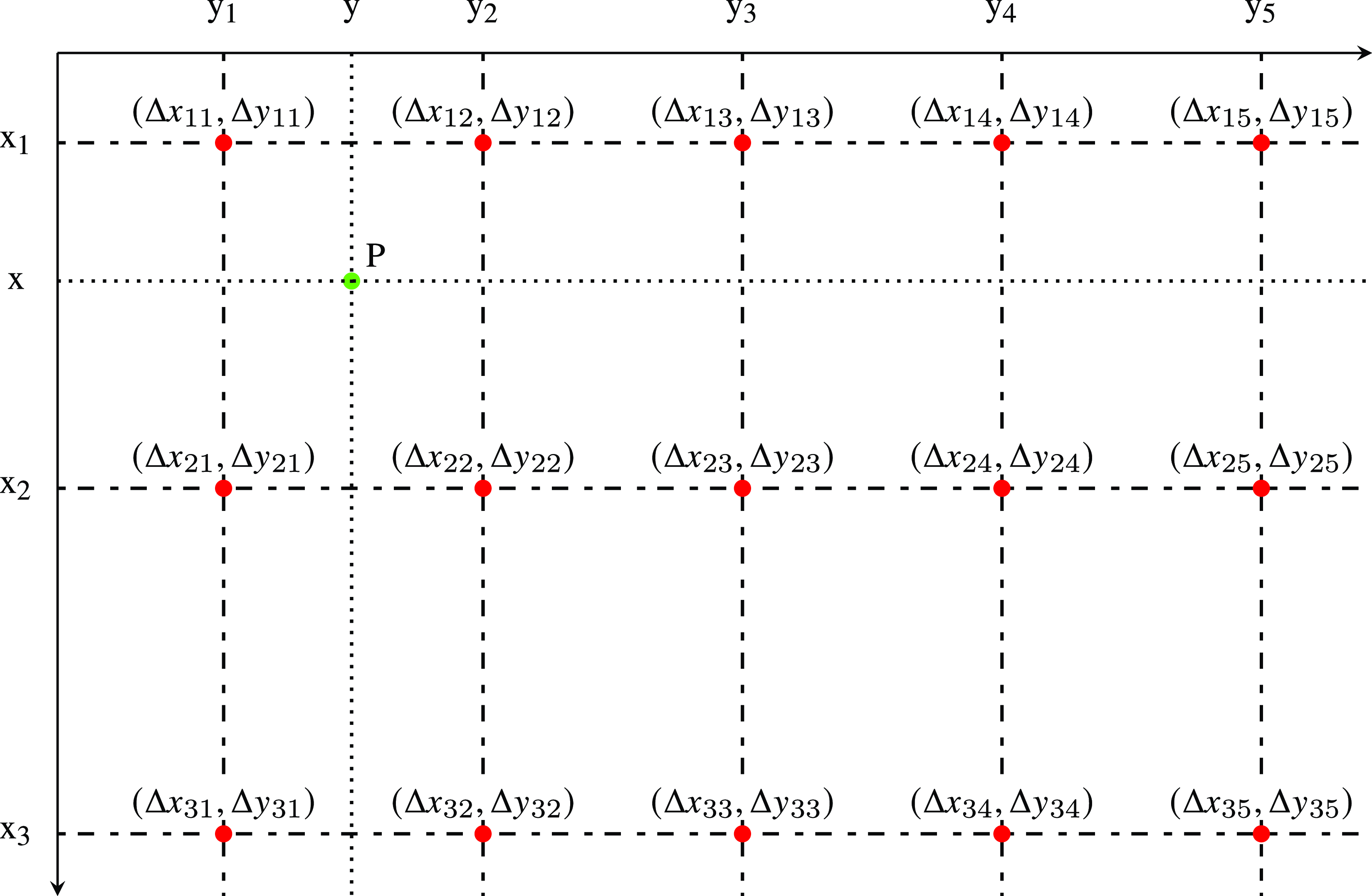
Considering a specified measurement point (
 $x_i,y_j$
), Equation 8 is modified as follows:
 \begin{align} \Delta{x}_{ij}=\Delta{x}_{ijF_{x}}+\Delta{x}_{ijF_{y}}=f_{1}(x_{i},y_{j},F_x)+f_{2}(x_{i},y_{j},F_y) \nonumber \\[3pt] \Delta{y}_{ij}=\Delta{y}_{ijF_{x}}+\Delta{y}_{ijF_{y}}=g_{1}(x_{i},y_{j},F_x)+g_{2}(x_{i},y_{j},F_y) \end{align}
where the indices
 $ij$
indicate the end-effector location for measurement points as shown in Figure 5. For instance,
 $\Delta{x}_{11}$
specifies the total compliant displacement at the
 $x$
-direction of the top-left end-effector position
 $(x_{1},y_{1})$
and
 $\Delta{x}_{11F_{x}}$
is the compliant displacement along the
 $x$
-direction because of the external force
 $F_{x}$
applied at that measurement point. It is observed during the stiffness measurement tests in the static conditions that there is almost a linear relationship between the increasing external forces and increasing compliant displacements at each specified measurement point [Reference Paksoy, Dede and Kiper31]. However, because of the different internal stress conditions in different locations of the workspace when there is no forcing on the mechanism, different compliant displacements can occur in these conditions. Considering this bias term in compliant displacement due to internal stress of the mechanism, a total of four linear functions are fitted to represent compliant displacements
 $\Delta{x}_{ij}$
and
 $\Delta{y}_{ij}$
at each measurement point:
 \begin{align} \Delta{x}_{ijF_{x}}&=m_{ij}F_x+n_{ij} \nonumber \\[3pt] \Delta{x}_{ijF_{y}}&= o_{ij}F_y+p_{ij} \nonumber \\[3pt] \Delta{y}_{ijF_{x}}&= s_{ij}F_x+u_{ij} \nonumber \\[3pt] \Delta{y}_{ijF_{y}}&= v_{ij}F_y+w_{ij} \end{align}
External forces along
 $x$
and
 $y$
are applied in an increasing order step by step represented by
 $F_k$
for the
 $k^{\text{th}}$
step. The array of applied forces is
 $F=[5\; 10\; 15\; 20 \;25]^T$
kgf (where the forces are approximately 10 times higher in newtons) for
 $k=1, \ldots, 5$
. Accordingly, Equation 10 is rewritten in the matrix form as follows:
 \begin{align}{\underbrace{\begin{bmatrix} \Delta{x}_{ijF_{kx}}\\[3pt]\Delta{x}_{ijF_{ky}}\\[3pt]\Delta{y}_{ijF_{kx}}\\[3pt]\Delta{y}_{ijF_{ky}} \end{bmatrix}}_{\bar{\Delta }_{F_k}}}^T = \left[\begin{array}{l@{\quad}l} F_{k} & 1 \end{array}\right] \left[\begin{array}{l@{\quad}l@{\quad}l@{\quad}l} m_{ij}&o_{ij}&s_{ij}&v_{ij}\\[3pt]n_{ij}&p_{ij}&u_{ij}&w_{ij} \end{array} \right] \end{align}
Open form of Equation 11 for
 $k=1, 2, \ldots, 5$
is given as follows:
 \begin{align} \underbrace{ \begin{bmatrix}{\bar{\Delta }_{F_1}^T}\\[3pt] \vdots \\[3pt]{\bar{\Delta }_{F_5}}^T \end{bmatrix}}_{\hat{B}}=\underbrace{\begin{bmatrix} F_{1}&1\\[3pt] \vdots \\[3pt] F_{5}&1 \end{bmatrix}}_{\hat{A}} \underbrace{ \left[\begin{array} {l@{\quad}l@{\quad}l@{\quad}l} m_{ij}&o_{ij}&s_{ij}&v_{ij}\\[3pt]n_{ij}&p_{ij}&u_{ij}&w_{ij} \end{array} \right]}_{\hat{Q}} \end{align}
where the first row and second row of the
 $\hat{Q}$
matrix represents the linear parts and offset parts of the polynomial functions, respectively.
 $\hat{Q}$
can be solved by using the least squares solutions for over-determined systems as follows:
 \begin{align} \hat{Q}=(\hat{A}^{T}\hat{A})^{-1}\hat{A}^{T}\hat{B} \end{align}
where it corresponds to one set of coefficients of linear functions at that
 $ij$
measurement point (a fixed configuration where the actuators are locked). That means, 15 sets of coefficients of linear functions are computed in total for all measurement points. These coefficients are tabulated in Appendix A.
Bilinear interpolation between the predicted compliant displacements
 $(\Delta{x_{ij}},\Delta{y_{ij}})$
(
 $x_i=122.132+50(i)$
and
 $y_j=-112.5+37.5(j)$
for i = 1:3 and j = 1:5).

After obtaining the coefficients of first-order polynomial functions,
 $\Delta{x}_{ij}$
and
 $\Delta{y}_{ij}$
can be predicted by using Equations 10 and 9, respectively, for any
 $F_x$
and
 $F_y$
external force at that measurement point.
In order to find the compliant displacement values
 $\Delta{x}$
and
 $\Delta{y}$
for
 $F_x$
and
 $F_y$
external forces at any end-effector location (
 $x,y$
), bilinear interpolation is carried out by using the compliant displacements measured at four neighboring measurement points. The measurement points are indicated in Figure 5. An example bilinear interpolation formulation is given as follows:
 \begin{align} \Delta{x_P}=\dfrac{\begin{bmatrix}{x_2-x}& \quad{x-x_1} \end{bmatrix} \left[\begin{array}{l@{\quad}l}\Delta{x_{11}}&\Delta{x_{12}}\\[3pt] \Delta{x_{21}}&\Delta{x_{22}} \end{array}\right] \begin{bmatrix}{y_2-y}\\[3pt]{y-y_1}\end{bmatrix}}{(x_2-x_1)(y_2-y_1)} \nonumber \\[3pt] \Delta{y_P}=\dfrac{\begin{bmatrix}{x_2-x}& \quad{x-x_1} \end{bmatrix} \left[\begin{array}{l@{\quad}l} \Delta{y_{11}}&\Delta{y_{12}}\\[3pt]\Delta{y_{21}}&\Delta{y_{22}} \end{array}\right]\begin{bmatrix}{y_2-y}\\[3pt]{y-y_1} \end{bmatrix}}{(x_2-x_1)(y_2-y_1)} \end{align}
where it estimates the compliant displacements for the point
 $P$
.
5. Test setup, procedure, and evaluation methodology for trajectory-tracking performance
This section introduces the test setup and procedure to compare the trajectory-tracking performance of 2-DoF over- and normal-constrained mechanisms. The importance of the CoM location of the moving platform is discussed by illustrating D’Alembert’s forces on a sketch drawing. Implementation of an image processing algorithm to evaluate end-effector trajectories is given, and the results are interpreted and reported.
5.1 Test setup and procedure
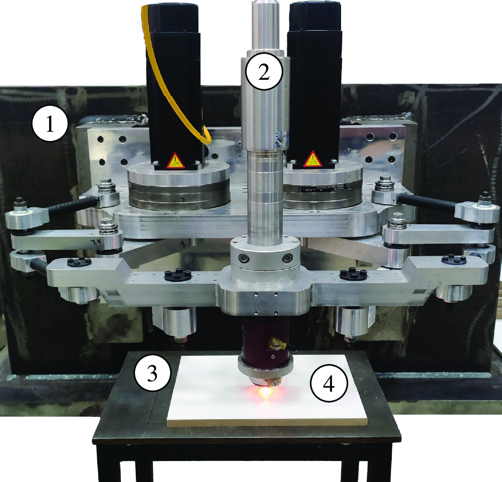
2-DoF planar over-constrained mechanism: 1:Base, 2: PHF-25 laser process head, 3: adjustable work table, 4: coated chipboard for laser marking.

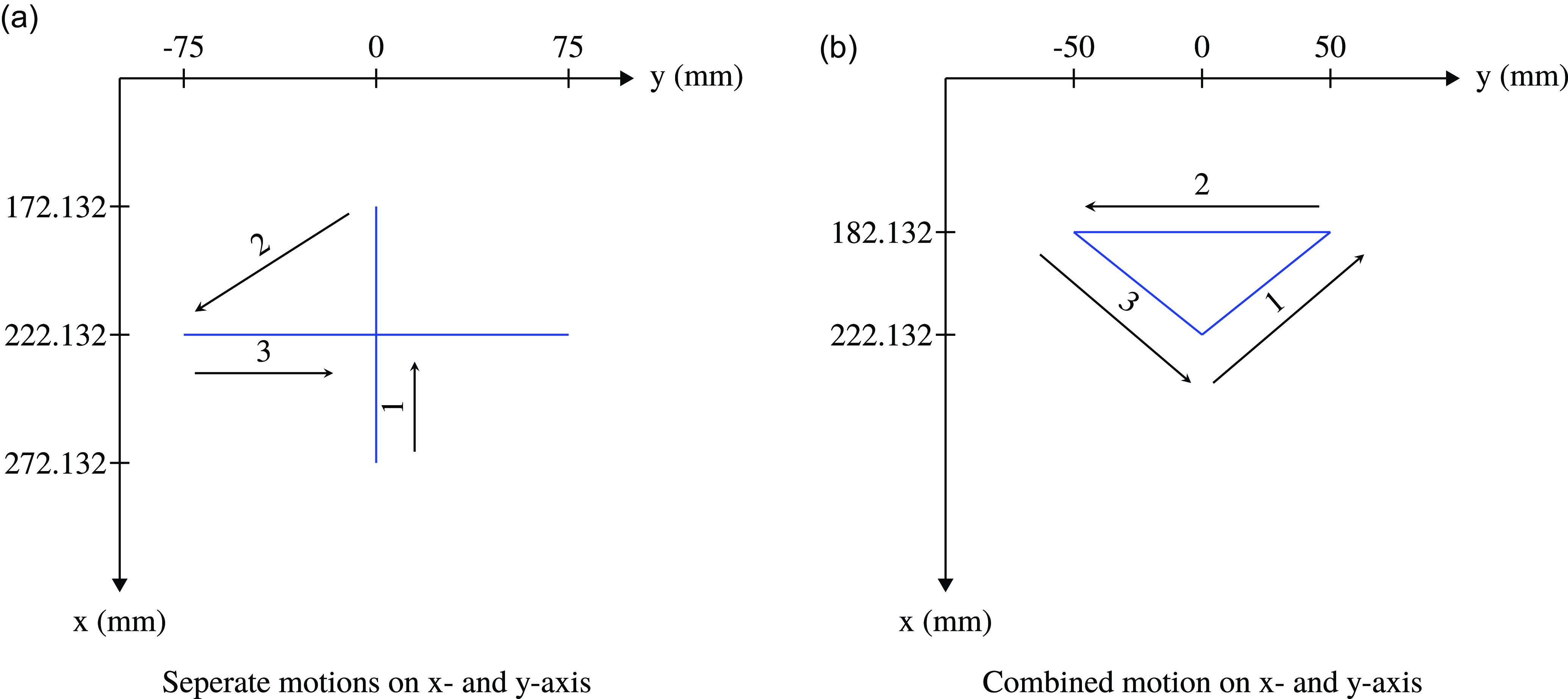
To compare the trajectory-tracking performances of the 2-DoF planar mechanisms, the experimental test setup and procedure are given. The laser head assembled mechanism with an adjustable work table and coated chipboard can be seen in Figure 6. The detailed electromechanical system that is used to conduct the tests is presented in Appendix B. To observe the end-effector path of the mechanism, the mechanism with the laser marker, a work table with adjustable height and orientation, and coated chipboard to be marked with the laser are used. For the evaluation of the dynamic performance of the mechanisms, the resultant paths that are marked with the laser are recorded digitally by using image processing algorithms. In this way, key features of resultant paths are obtained (Figure 7).
The dynamic performance tests are executed for eight different configurations. There are two structurally different mechanisms which are 2-DoF over-constrained and normal-constrained mechanisms (see Figure 3), two different laser head positions introduced as upper laser head position
 $G_{U}$
and lower laser head position
 $G_{L}$
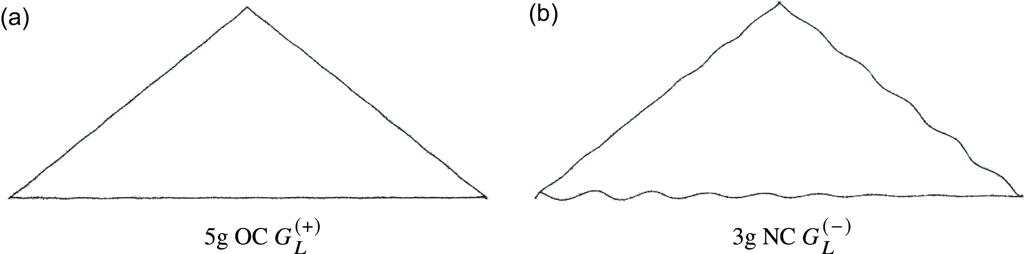
(See Figure 8), and mechanisms with compliance model algorithm and without compliance model algorithm. These eight different configurations are subjected to dynamic performance tests that measure the trajectory-tracking ability up to 5 g accelerations. Three different motions of the laser head are assigned for these tests which are x-axis motion, y-axis motion, and combined motion. The x-axis motion durations for motions with 1, 2, 3, 4, and 5 g accelerations are approximately 288, 272, 262, 255, and 253 ms, with corresponding acceleration/deceleration times of 56, 37, 26, 21, and 18 ms, respectively. The y-axis motion durations for motions with 1, 2, 3, 4, and 5 g accelerations are approximately 408, 391, 382, 377, and 375 ms, respectively, and the acceleration/deceleration times are the same with the x-axis motion. Similar motion profiles are designed for the combined motion where the motion durations for each side of the isosceles are 206, 188, 177, 172, and 169 ms for motions with 1, 2, 3, 4, and 5 g accelerations, respectively, and acceleration/deceleration times are the same with the x-axis motion profile. In Figure 7, these defined paths can be seen. The path in Figure 7a is defined for separate end-effector motions along the x- and y-axes, and its dimensions are limited with the measurement points defined in Figure 5. The path in Figure 7b is defined for combined end-effector motion, and its dimensions are defined so that a triangular path is tracked within the measurement point defined in Figure 5. The arrows with the numbers sketched in Figure 7 define the end-effector motion sequence. While executing the dynamic performance tests for the cases where the trajectory updating algorithm is enabled, the trajectory update procedure given in Figure 2 is used. In this flowchart diagram, there is a gain
 $m_{E}$
that represents the mass of the end-effector which is multiplied by the end-effector accelerations
 $\bar{\alpha }_{E}$
to compute the D’Alembert’s forces
 $\bar{F}_{D}$
. The actual mass of the moving platform including the end-effector is approximately 3.6 kg. However, since the masses of the links are neglected, mass parameter
 ${m_E}^*$
can be selected higher than 3.6, and this may result in better compensation for the trajectory-tracking error. Therefore, preliminary tests are carried out to find a more suitable mass value to minimize the tracking error. It must be noted that a suitable parameter is an assumption neglecting the different motion characteristics of the links which are not the same as the moving platform. Therefore, a varying error performance is expected at different locations of the workspace. However, since the manipulator is lightweight with a relatively large payload, these variations are expected to be small. As a result of this mass parameter search, the mass parameter
 ${m_E}^*$
is tuned as 5 kg during the pre-evaluation tests. This chosen mass parameter is used for all experiments to maintain consistency.
Defined paths for dynamic performance evaluation.

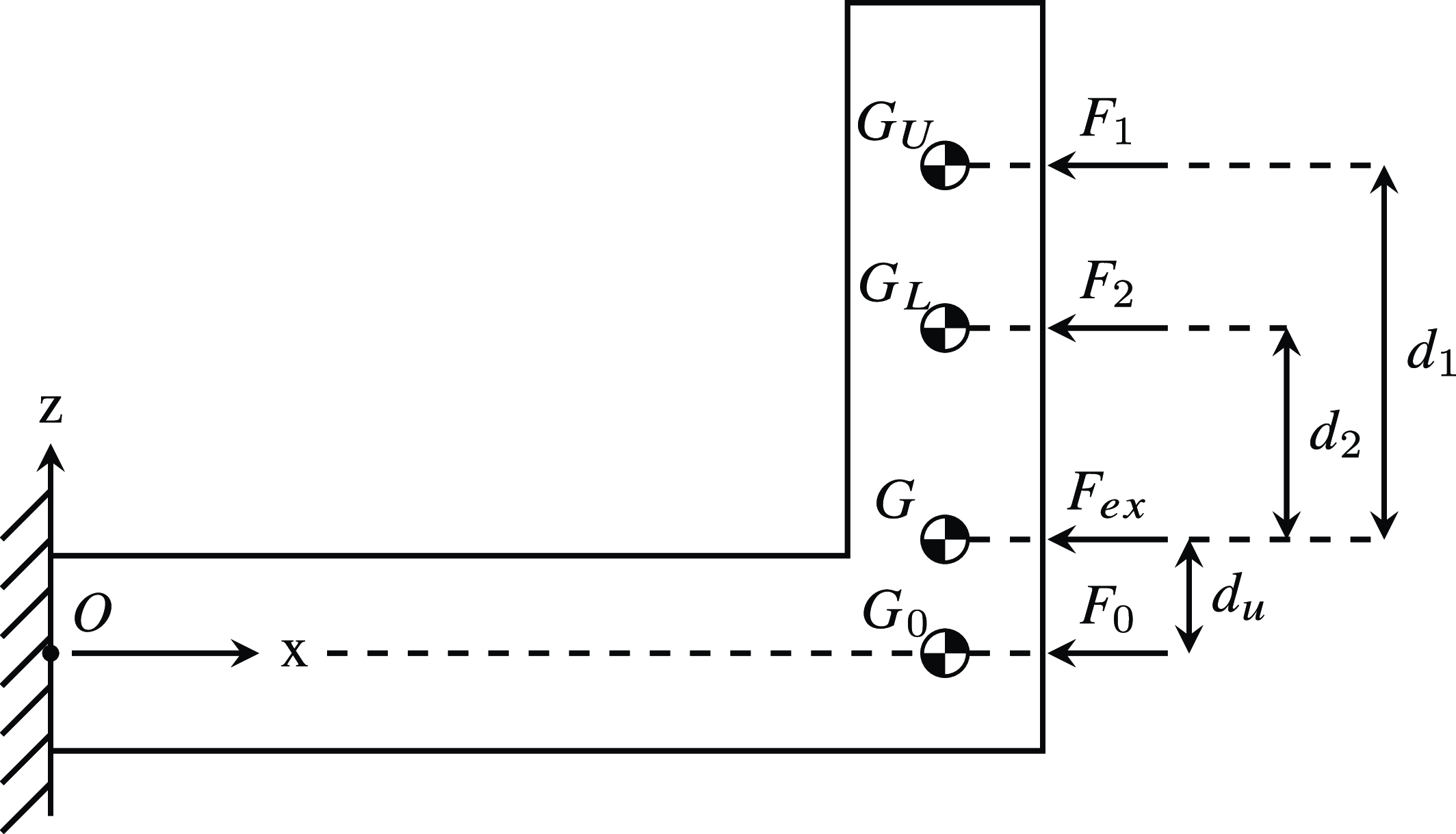
Forces acting on the robot with their CoM locations.

5.2 Importance of the end-effector’s center of mass (CoM) location
The laser head’s mass accounts for roughly half of the platform’s mass. Therefore, the location of the laser head along the vertical axis is important for arranging the CoM position of the moving platform, which also determines the location of D’Alembert’s forces under dynamic conditions. In Figure 8, the side view of the mechanism presented in Figure 4b is represented as an L-shaped body that is fixed at the point
 $O$
to the ground. In this figure, there are three D’Alembert’s forces
 $F_{0}$
,
 $F_{1}$
, and
 $F_{2}$
that have the same magnitude (obtained for the same motion) acting at three centers of mass locations
 $G_0$
,
 $G_U$
, and
 $G_L$
, respectively. These locations of CoM are obtained from the CAD model of the mechanism. Points
 $G_U$
and
 $G_L$
are the CoM of the moving platform where the laser head is mounted in relatively higher and lower positions along the z-axis, respectively. Point
 $G$
is the CoM of the moving platform including the replica of the laser head where the external forces
 $F_{ex}$
are applied during the static condition tests to collect the compliant displacements of the mechanisms. Due to their different vertical positions of application, these forces will create a different amount of moments that will result in different amounts of bendings. These moments are about point
 $O$
given as follows:
 \begin{align} \overrightarrow{M_{1}^O}&=(\overrightarrow{d_{1}}+\overrightarrow{d_{u}})\times \overrightarrow{F_1} \nonumber \\[3pt] \overrightarrow{M_{2}^O}&=(\overrightarrow{d_{2}}+\overrightarrow{d_{u}})\times \overrightarrow{F_2}\nonumber \\[3pt] \overrightarrow{F_0}&=\overrightarrow{F_1}=\overrightarrow{F_2} \end{align}
where the magnitudes of all applied forces are equal. If the line of action of the exerted force passes through the fixed point
 $O$
, there will be no moment on the body due to this force. This is the case for the exerted force
 $F_{0}$
acting at point
 $G_{0}$
and the body will be exposed to deformation only along the axial direction. Point
 $G_{0}$
is located slightly below point
 $G$
at an undetermined distance
 $d_{u}$
. This distance
 $d_{u}$
cannot be determined since the mechanism is connected to the fixed platform at four different locations at two different levels in the vertical direction making the system statically indeterminate. The dimensions
 $\left \lvert \overrightarrow{G_{U}G}\right \rvert$
and
 $\left \lvert \overrightarrow{G_{L}G}\right \rvert$
are given as follows:
 \begin{align}{d_{1}}&=\left \lvert \overrightarrow{G_{U}G}\right \rvert = 35.9mm \nonumber \\[3pt]{d_{2}}&=\left \lvert \overrightarrow{G_{L}G}\right \rvert = 5.3mm \end{align}
where they are denoted as
 $d_{1}$
and
 $d_{2}$
, respectively.
In this case, during the trajectory-tracking experiments, there are two different CoM conditions of the moving platform and thus, two different conditions for the occurrence of D’Alembert’s forces.
 $G_{L}$
slightly deviates from the point
 $G$
along the vertical direction, while
 $G_{U}$
is located roughly seven times further away from
 $G$
along the z-direction with respect to the
 $G_{L}$
. The experiments are designed to observe the effect of the different heights of the end-effector on the compliant displacements of the robot, and the information of the CoM of the end-effector is not accounted for in calculation of the compliance matrix.
5.3 Evaluation methodology for trajectory-tracking performance: image processing algorithm
In this section, to gather information from the laser-marked chipboards containing end-effector paths, an image processing methodology is developed. The image processing algorithm takes place in six steps;
-
(i) By using a 1200 dpi scanner, marked paths on the chipboard are scanned .
-
(ii) Filtering process is performed on the captured data to filter out the noisy data.
-
(iii) Coordinates of pixels that are related to the marked path are specified.
-
(iv) Spline and line fitting processes are executed for these pixels by using the fit and polyfit functions in MATLAB, respectively.
-
(v) Pixel coordinates information is transformed to SI units in terms of mm by using the dpi information of the scanner.
-
(vi) Key features of total path distance and the total area between the designated path and the marked path are calculated.
Detailed procedure for the image processing algorithm for the extraction of the key features is presented in Appendix C.
6. Test Results
During the tests, three different motion profiles (
 $x$
- motion,
 $y$
-motion, and combined motion) are used as explained in Figure 7. The distance covered during the marking process of motion is measured between the start and end point of the trajectories. In order to express the deviation from linearity, the total area has been measured as the area between the fitted line and fitted spline.
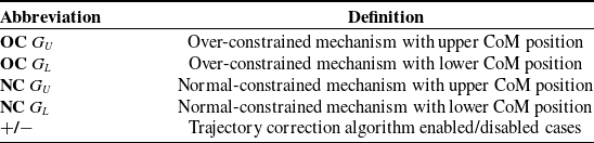
Among these motion profiles, the triangular motion has a distinctive characteristic since the marking along one direction motion starts where the marking of the previous motion along a different direction ends. As a result of compliant displacements due to high dynamic forces in these instances, the corners are not obtained at their desired locations. Hence, the image processing algorithm results in fitted lines that do not exactly pass through the corners. Consequently, each side of the triangle is processed as a single-line path. In fact, the reason to have triangular path tests is not to test if the perfect triangle is obtained but to test for a combined motion. Hence, the data along the y-axis motion (baseline of the triangle) is excluded since this type of motion results are covered in the previous tests. The total area of path-tracking error for the triangular path is calculated by summing up the areas obtained for the isosceles sides of the triangle. Additionally, the distance covered along each direction could not be calculated uniquely during the triangular motion, since the marking process is not halted during the change of direction and the next motion starts where the previous one ends. Therefore, the distances covered along the sides of the triangle are not reported. In Table I, the abbreviations to explain the mechanism configurations for the performance tests are given. For NC
 $G_{L}$
configurations, the maximum acceleration reached during the tests is up to 3 g. The main reason for this limitation is that at 3 g accelerations during triangular path tests with NC
 $G_{L}^{(-)}$
configuration, there was unexpected noise from the mechanism which might indicate damage to the mechanism if further tests with this configuration are continued. As a result, with the exception of this mechanism configuration (NC
 $G_{L}$
), the tests for both trajectories with all other mechanism configurations are performed at 5 g.
Abbreviations for different mechanism configurations.

6.1 Test results for y-axis motion
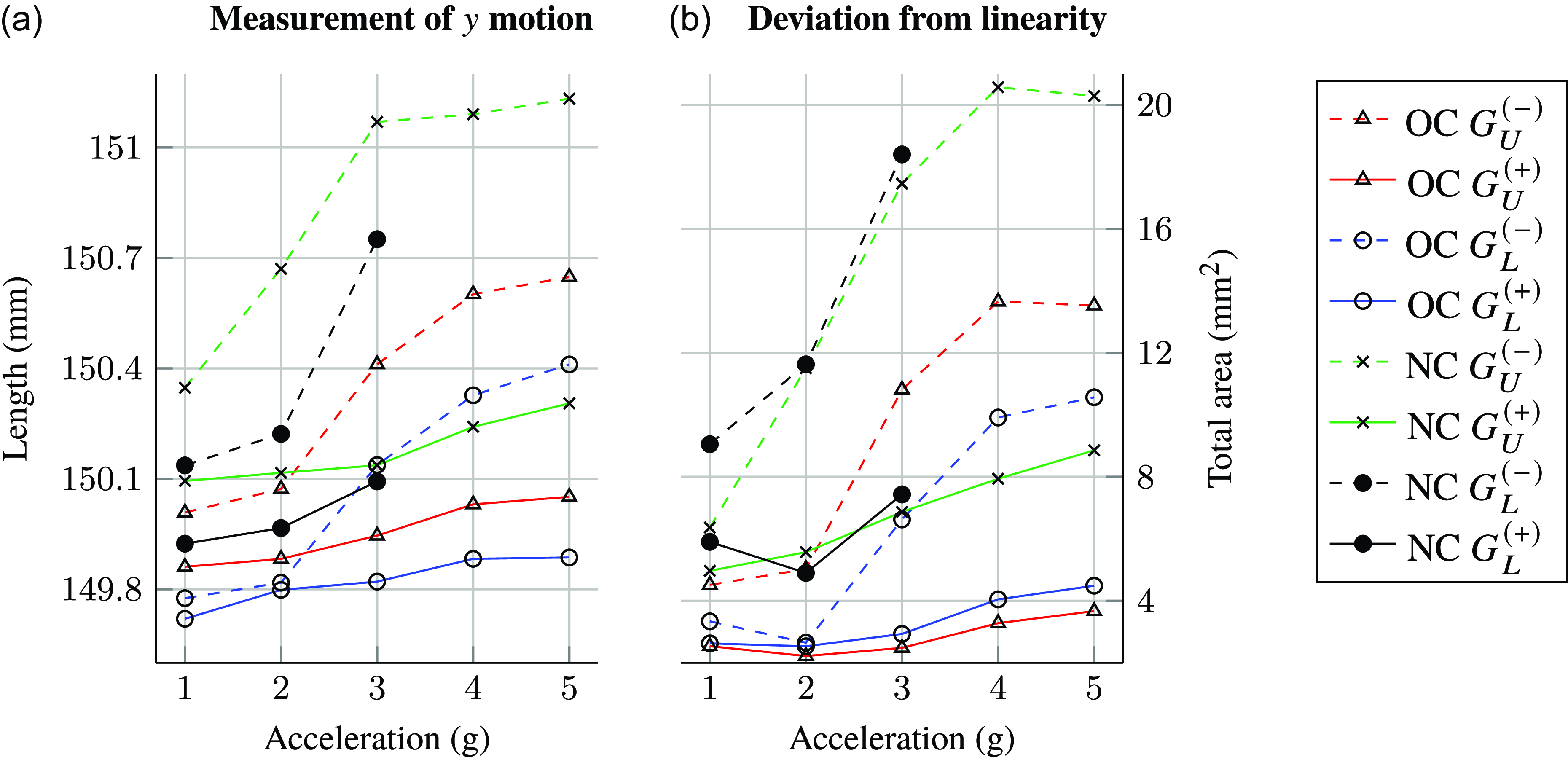
In Figure 9, the trajectory following performances along the
 $y$
-axis motion are given. The designated motion is defined as 150 mm straight line along the
 $y$
-axis.
Trajectory following performance along the
 $y$
-axis.

In Figure 9a, the distance covered from the start until the end of motion with respect to the increasing accelerations from 1 g to 5 g is plotted. Static calibration of the mechanism is executed at the OC
 $G_{U}^{(-)}$
configuration. For that condition, the length of the straight line
 $y$
motion is measured to be around 150 mm at 1 g acceleration. As the maximum acceleration of the motion reaches 5 g, line length measurement values go up to 150.7 mm due to the compliance of the mechanism.
The obtained results indicate different line lengths even at 1 g acceleration. This is mainly due to the static calibration configuration OC
 $G_{U}^{(-)}$
. Therefore, the results presented in Figure 9a should be compared based on how the line length changes when the acceleration is increased for each test configuration.
To clearly visualize the difference in the performance when the correction algorithm is enabled and disabled for the same conditions in terms of the type of constraint and placement of the end-effector, the same color and marking type are used. It can be seen in Figure 9 that for all mechanism configurations, the range of the length measurement along
 $y$
- motion is decreased to a smaller length when the correction algorithm is activated.
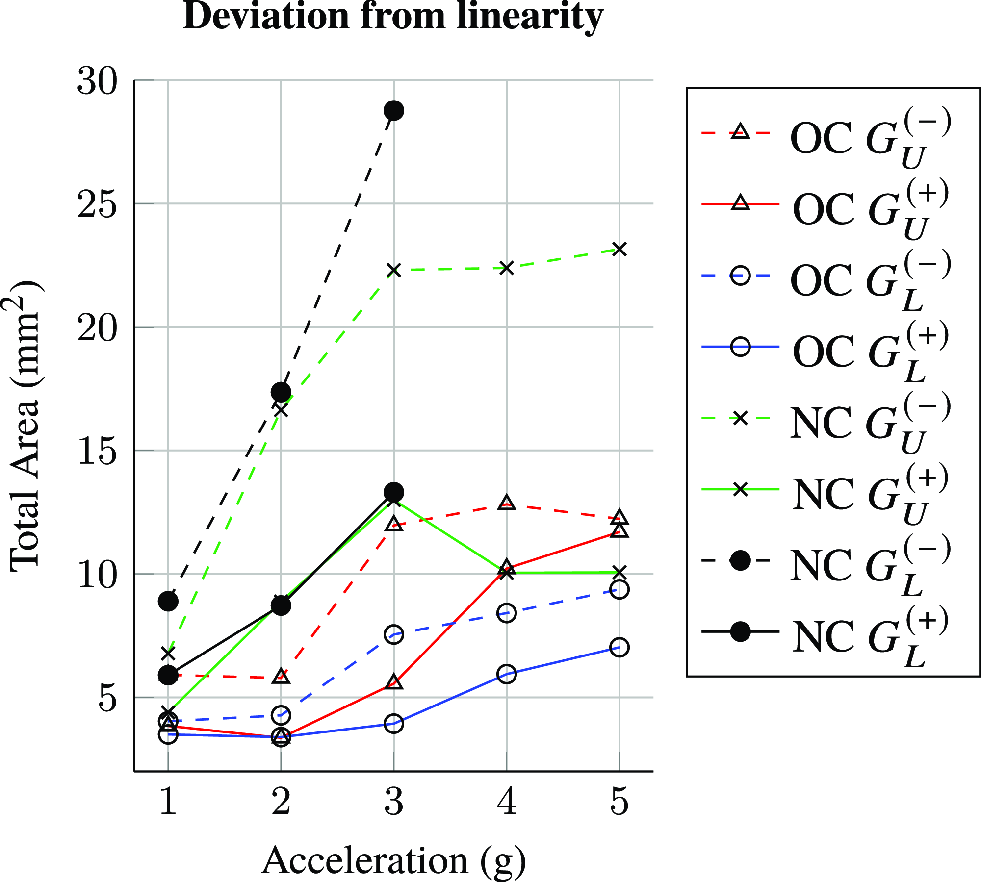
In Figure 9b, deviation from linearity is defined as the total area of path-tracking error and given for increasing accelerations from 1 g to 5 g. The results presented in Figure 9b are independent of the calibration configuration. The deviation from linearity obtained for each test configuration provides information about the magnitudes of vibrations during achieving the desired motion.
To easily compare the test results, for the line length measurement, a new term
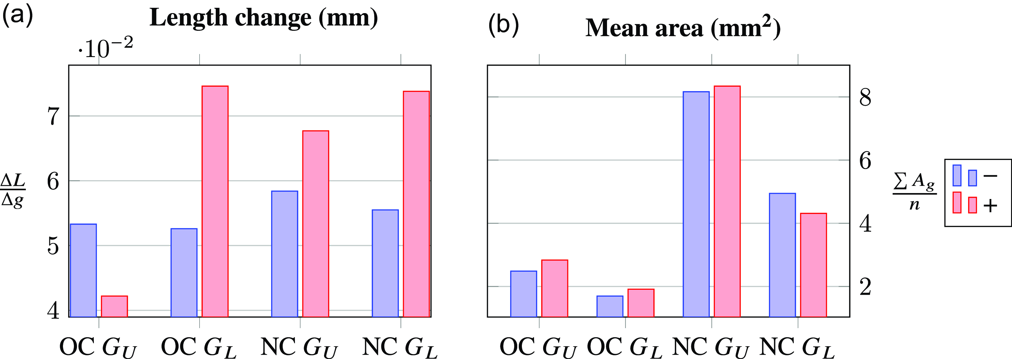
 $\frac{\Delta{L}}{\Delta{g}}$
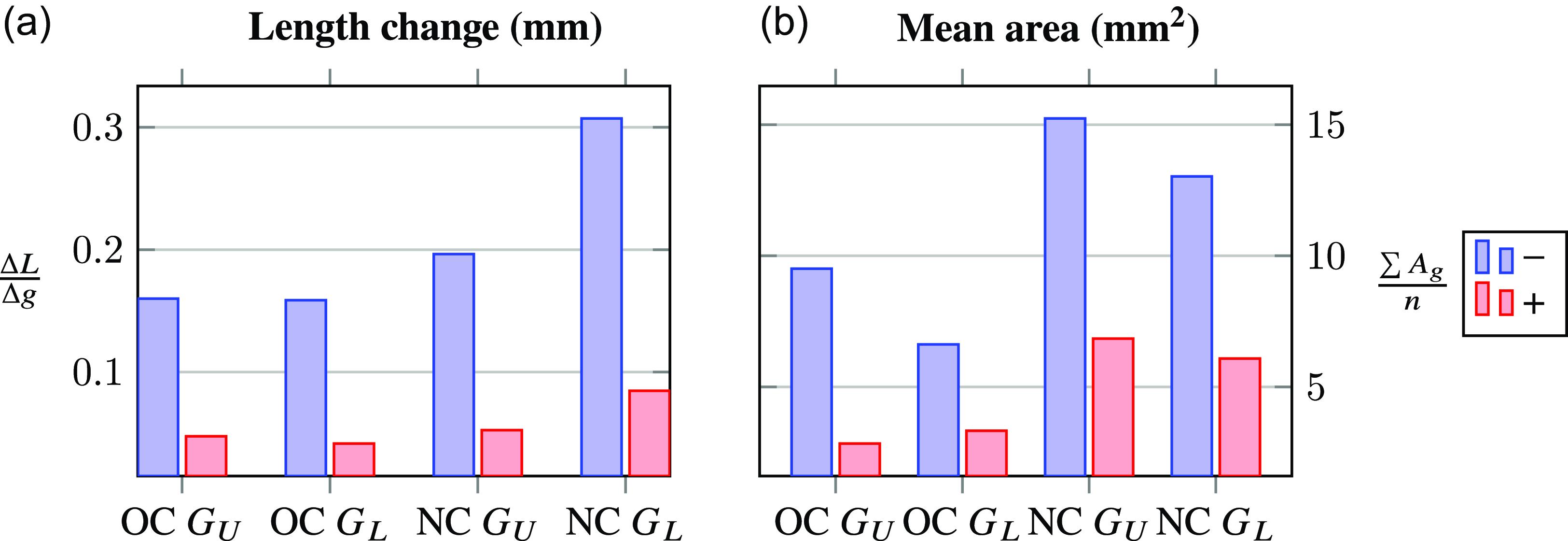
is defined. It presents the deviations from the desired line length with respect to the increasing accelerations. To indicate the deviations from linearity, the total areas of path-tracking errors for all accelerations are summed
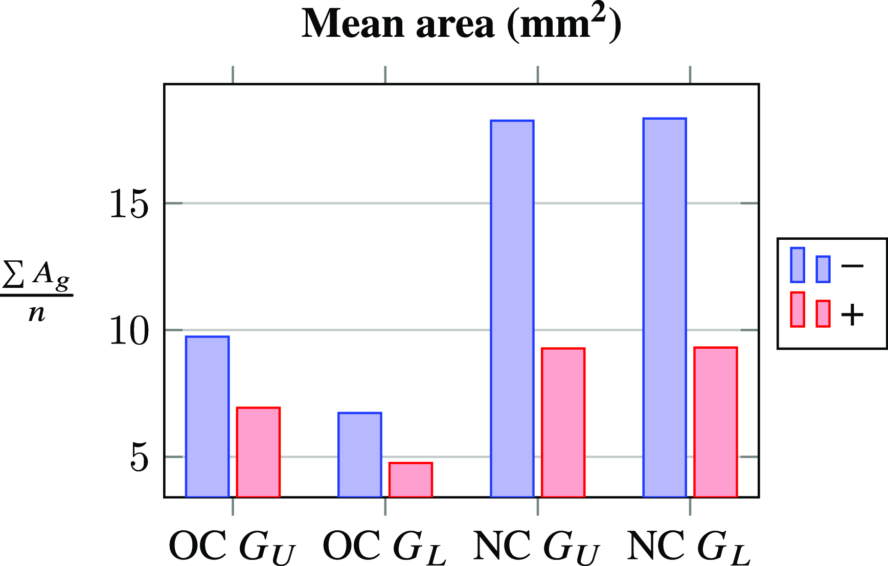
 $\frac{\sum{A_g}}{n}$
and divided by the number of acceleration conditions
 $n$
where
 $g=1, \ldots, n$
. The total number of acceleration conditions
 $n$
is 3 for NC
 $G_{L}$
configurations, whereas the other configurations have 5.
In Figure 10a, the trajectory-tracking performances in terms of deviations from the desired line length for each configuration are depicted. It can be observed in Figure 10a that enabling the correction algorithm decreases the deviations in the obtained line length as the accelerations increase and line length deviations obtained for the over-constrained mechanism configurations are smaller with respect to the one obtained for the normal-constrained mechanism configurations.
In Figure 10b, the mean of the total areas of path-tracking errors of all accelerations with respect to each configuration is presented for the motion along the y-axis. As observed in Figure 10b, it can be said that enabling the correction algorithm decreased the vibrations for all cases. For the cases without the correction algorithm, lower laser head position (
 $G_{L}$
) conditions for both OC and NC mechanism configurations indicate lower vibrations relative to the upper laser head position conditions. However, since the NC
 $G_{L}^{(-)}$
configuration tests are up to 3 g accelerations, it is fair to only consider OC results for this discussion.
Considering the OC configurations, when the correction algorithm is enabled, the range of vibrations got slightly smaller with the upper end-effector condition relative to the lower end-effector condition. This may have originated from the selection of the mechanism’s configuration as OC
 $G_U$
when the mass parameter
 ${m_E}^*$
indicated in Figure 2 is arranged. Therefore, the compliance data might fit better to this condition OC
 $G_U$
.
6.2 Test results for x-axis motion
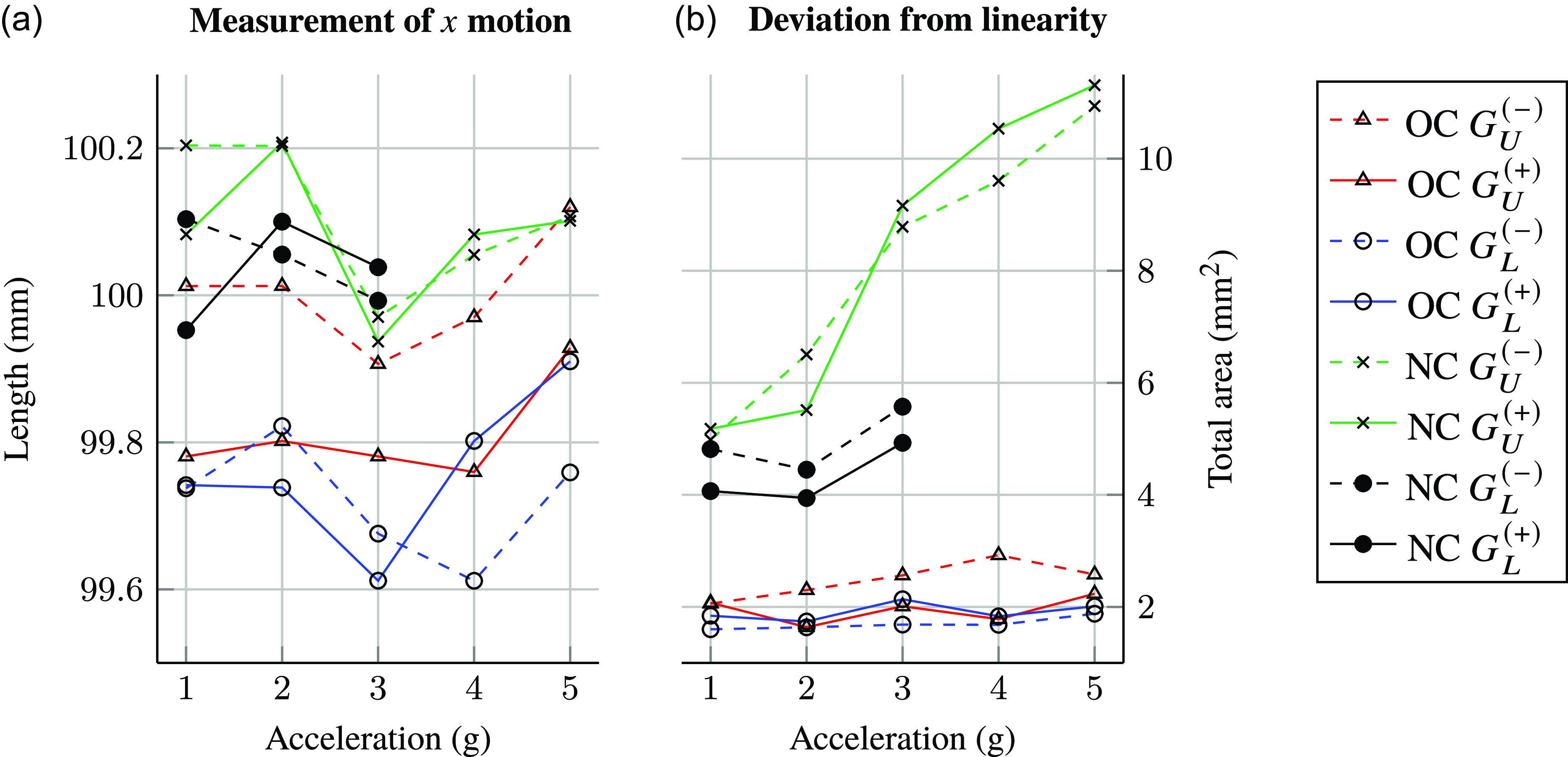
In Figure 11, trajectory-tracking performances along the
 $x$
- axis are given. The desired trajectory is 100 mm of a straight line along the x-axis when
 $y=0$
. When a motion is defined for the
 $y=0$
condition for this mechanism, the OC mechanism’s links on the left and right of the x-axis move symmetrically. Hence, the OC mechanism’s results are expected to have small deviations from linearity. In Figure 11a, the line length measurement obtained from the
 $x$
-axis motion tests is plotted. It should be noted that the change in the line length measurements for each configuration as the accelerations are increased is very small. Therefore, a confident deduction cannot be made for these test results.
Trajectory following performance along the
 $y$
-axis in terms of length change and mean area.

Trajectory following performance along the
 $x$
-axis.

In Figure 11b, deviations from linearity obtained from the
 $x$
-axis motion test can be seen. It is clear that OC configurations show better performance with respect to the NC configurations. Due to the symmetric nature of OC configuration, very small compliant displacements along the axis
 $y=0$
are expected. Deviations for the OC conditions are smaller throughout the motions with various accelerations in the range of
 $[1.6, 3]$
 $\text{mm}^{2}$
compared to the results obtained with the NC mechanisms:
 $[4, 12]$
 $\text{mm}^{2}$
. These results actually verify the aforementioned statement on compliant displacements along the y-axis for the OC mechanism.
Trajectory following performance along the
 $x$
-axis.

In Figure 12a, the trajectory-tracking performances in terms of deviations from the desired line length for each configuration are depicted. In Figure 12a, it can be seen that the length deviations are in the order of
 $10^{-2}$
mm/g. Therefore, it can be said that the results displayed in this table are around the accuracy range of the image processing algorithm. Although the deviations are in a small range for each configuration, only the mechanism configuration OC
 $G_U$
results in a smaller deviation of line length when the correction algorithm is enabled. Since the execution of static calibration is carried out in this configuration, the accurate behavior of the OC
 $G_U$
configuration after enabling the correction algorithm.
In Figure 12b, the mean of the total areas of path-tracking errors of all accelerations for each configuration is presented for the motion along the x-axis. In contrast to the results obtained for the y-axis motion, enabling the correction algorithm did not decrease the vibrations substantially in all cases. This result was expected due to the following investigations: (i) very small compliant displacements are expected during the motion along the x-axis where the mechanism is in a symmetrical configuration (motion when
 $y=0$
). (ii) However, during the static condition tests when
 $y=0$
and the force is applied along the x-axis, compliant displacements measured in the y-axis are in the order of measurement tolerances of the CMM (Coordinate Measuring Machine). (iii) Consequently, the output of the correction algorithm is not as reliable as it was for the tests carried out in other conditions where the compliant displacements measured are much larger than the tolerance of the CMM.
6.3 Test results for triangular motion
In Figure 13, the deviation from linearity in terms of the total area is given for the combined motion where the baseline image processing information is not included in the calculations. The highest deviation is observed for the case NC
 $G_{L}^{(-)}$
configuration at 3 g accelerations. Further tests with larger accelerations for this condition are not carried out due to the reasons explained previously. The vibration-related characteristics are similar to the ones obtained in
 $y$
-axis motion. However, for the combined motion, the best case in vibrations is clearly observed for OC
 $G_{L}^{(+)}$
case while for the
 $y$
-axis motion, OC
 $G_{U}^{(+)}$
shows slightly better performance. In Figure 14, the mean of the total areas of path-tracking errors of all accelerations for each configuration is presented for the combined motion. Since this combined motion captures a general characteristic of the mechanism throughout its workspace, the following deductions can be made in general: (i) it can be seen that the correction algorithm by estimating the compliant displacements of the end-effector compensates the deviations from the desired path, (ii) OC mechanism shows better performance with respect to the NC mechanism in terms of better trajectory-tracking performance with or without correction algorithm, (iii) especially for the OC mechanism, the lower laser head position resulted in smaller compliant displacements with respect to the upper laser head position condition.
Trajectory following performance for the combined motion.

Trajectory following performance along the
 $xy$
-axis (combined motion).

6.4 Illustrations of the best and worst cases
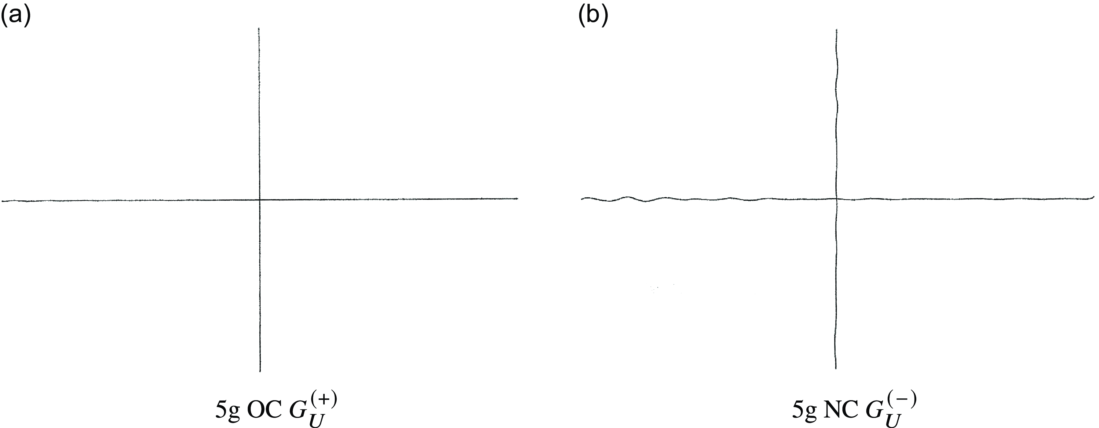
According to the total deviation from linearity results, the best and worst cases in terms of trajectory-tracking performance at the possible maximum accelerations are illustrated in Figures 15 and 16. In Figure 15, the cases for the
 $x$
and
 $y$
motions, and in Figure 16, the cases for the combined motion can be seen. Investigating the worst cases, it can be said that the vibrations start at the beginning of the motions and then dampens out (Figure 17, Figure 18). Even though it cannot be clearly observed in Figures 15 and 16, as the robot is close to the terminal position of the path, the tip point moves slightly away from the designated path as can be seen in Figure 19. This may be due to the release of the potential energy stored in the compliant bodies of the mechanism.
Illustrations of the best and worst cases for
 $x$
and
 $y$
motion for the possible maximum accelerations.

Illustrations of the best and worst cases for the combined motion for the possible maximum accelerations.

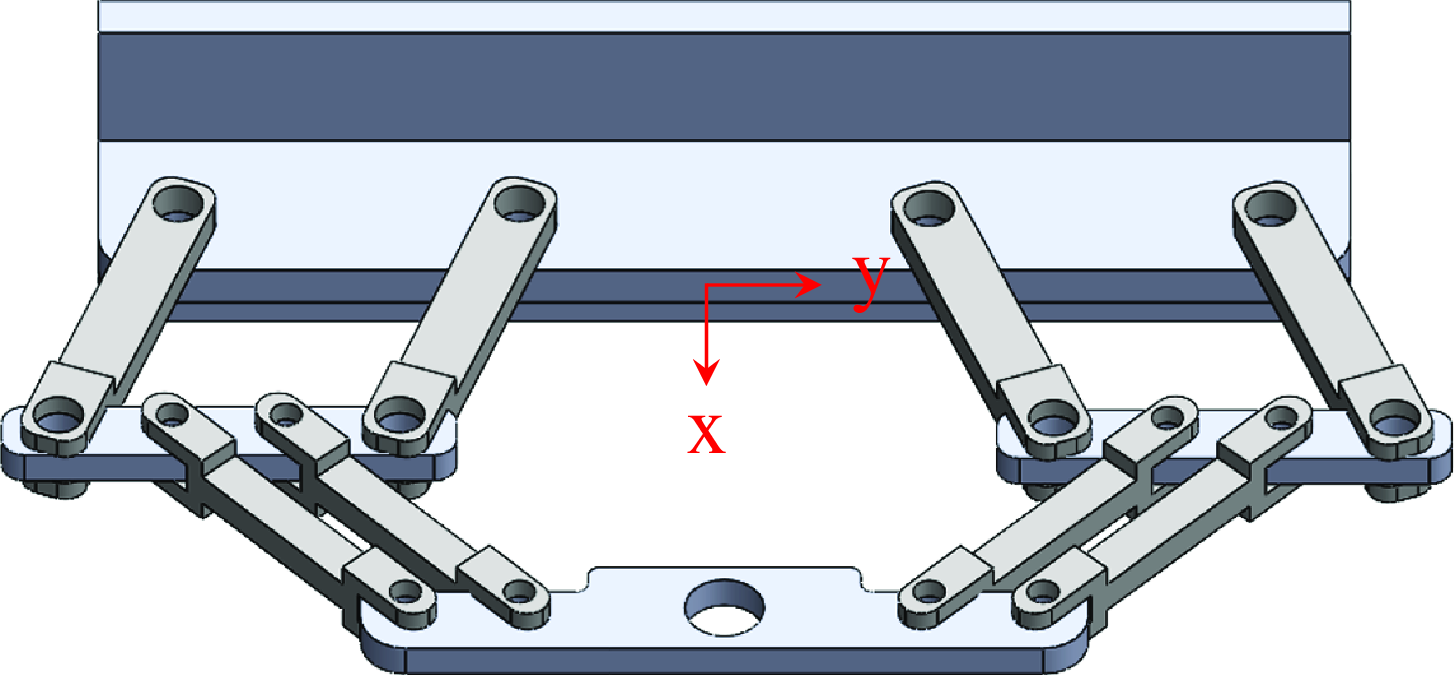
An alternative symmetrical design throughout an xy plane for the 2-DoF over-constrained mechanism where the optimal CoM point of the end-effector along the z-direction
 $G_{0z}$
is inherently defined to prevent the compliant displacements as a result of bending.

7. Discussion
The significance of this research lies in its innovative approach to addressing a critical challenge in high-acceleration robotic operations without the need for modifications to the existing controller. Nonlinear controllers have been employed to enhance trajectory-tracking accuracy in industrial systems [Reference Yin and Pan32]. However, in industrial robots, generally cascade PID controllers that are embedded into the servo drivers are used. Therefore, changing this controller with the nonlinear controller may result in lower sampling rates since the controller is designed externally (outside the servo driver). This situation can cause a loss of accuracy and stability problems in the control of high-acceleration robots. These conditions have limited the use of nonlinear controllers in industrial robot applications. This work has shown that by avoiding the necessity to alter controllers, the proposed approach can enhance the trajectory-tracking accuracy of high-accelerated parallel robots by ensuring compatibility with existing industrial setups, as exemplified in Figure 18 where the AKD-Kollmorgen servo drivers are used as controllers.
Although this novel approach is applied to a specific case where the robot is a planar one and the end-effector of the robot has 2-DoF, it can be extended to a high DoF robot case. In that situation, gravitational forces that varies with respect to the position of the end-effector will get involved to compliant displacement calculation during the operation and also, not only D’Alambert forces but also D’Alambert moments will play a role which is mentioned in Equation 3.
It should be noted that there are some limitations of our novel approach presented in this paper. The trajectory-tracking updating algorithm is based on a compliance model that is generated with the force and compliant displacement data gathered from measurements conducted at static condition. This data is collected once at specific environment circumstances, for example, a specific temperature. The compliance behavior of the links can be changed under different environmental circumstances. Even when the environment circumstances are the same, after a certain period of use, the compliance behavior of the robot can change due to wear of components. Therefore, calibration of the compliance model may be needed by performing the static test measurements periodically and environmental condition related parameters can be included in the model.
Another limitation is the lightweight and high-payload robot assumption that allows us to consider the whole moving components of the mechanism as a point mass. The formulation based on this assumption is given in Section 2. If considering a mechanism as a lightweight and a high-payload robot is not reasonable and will result with the unacceptable errors, then physical properties of the moving links (i.e., mass center, mass, and inertia) can be included to formulation. Therefore, there will be increased amount of calculations to predict the compliant displacements at the end-effector that will increase the computation time. Moreover, to enhance the estimation of compliant displacements, D’Alambert forces/moments can be calculated by using the measured accelerations from an inertial measurement unit. However, the used of this sensor has some drawbacks that are explained in
 $6^{\text{th}}$
paragraph of Section 1.
8. Conclusions
In this study, a trajectory correction algorithm is proposed for high-acceleration machinery using D’Alembert’s forces for dynamic loading. This algorithm is tested on a 2-DoF planar mechanism and its versions. The mechanism is reconfigured to be over-constrained in one of the versions. The placement of the end-effector along the normal of the plane of motion is changed to upper and lower conditions. Consequently, four configurations are tested with and without the trajectory correction algorithm. The findings and outcomes of the paper are presented as follows:
-
(i) OC mechanism presents better trajectory-tracking performance than NC mechanism even at high-acceleration motion.
-
(ii) It is shown that the CoM of the end-effector affects the trajectory-tracking accuracy of the mechanism.
-
(iii) The proposed trajectory correction algorithm significantly enhances the trajectory-tracking accuracy of the mechanisms.
The combined motion and y-axis motion do not have a special condition such as symmetry of the mechanism during its motion. Therefore, it was possible to evaluate the effect of the end-effector’s placement in a just way through the results of these tests. The mass center of the end-effector along the normal of the plane of motion in the lower laser head condition
 $G_{L}$
is closer to the optimal mass center
 $G_0$
with respect to the mass center at
 $G_{U}$
. Accordingly, the vibrations induced due to the moment arm formed between the actual mass center and the optimal one is smaller in the
 $G_{L}$
conditions. Hence, considering the vibration characteristics that can be observed from Figures 10b and 14, the lower condition exhibits better performance as expected.
One condition that contradicts the (iii) statement is the motion along the x-axis when
 $y=0$
. This motion has a special characteristic in which the mechanism moves symmetrically with respect to the
 $y=0$
line. In this condition, the vibrations along the y-axis are expected to be zero ideally. Accordingly, the deviations from the trajectory measured in all conditions with this motion profile are close to the tolerance level of the measurement system as can be seen in Figure 12b. Consequently, the improvement in trajectory-tracking when the algorithm is enabled could not be observed clearly. For future studies, the following can be taken into consideration to enhance the trajectory-tracking performance of the mechanism even more:
(i) The location of the optimal CoM of the end-effector
 $G_{0}=[G_{0x}\; G_{0y}\; G_{0z}]$
can be found by an experimental method. Another way is to redesign 2-DoF over-constrained mechanism so that there are no offsets along the z-axis. An example design is shown in Figure 17 where ternary joints are decomposed into binary joints to prevent the link offsets along the z-direction.
As a conclusion, the ability to enhance trajectory-tracking accuracy in high-acceleration scenarios without the need for controller modifications aligns with the constraints often encountered in industrial setups. This makes the proposed approach a valuable contribution to the field of control of high-acceleration industrial robots.
Author contributions
EP formulated the procedure presented in this paper, and he was in charge of conducting the tests and writing the draft paper; CD developed the idea of using the compliance model in trajectory enhancement, reviewed the test results, and contributed to the article writing process; GK was in charge of the whole study and contributed to the article writing process.
Financial support
The study is supported in part by The Scientific and Technological Research Council of Turkey via grant number 116M272.
Competing interests
The authors declare no conflicts of interest exist.
Ethical approval
Not applicable.
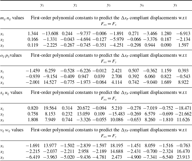
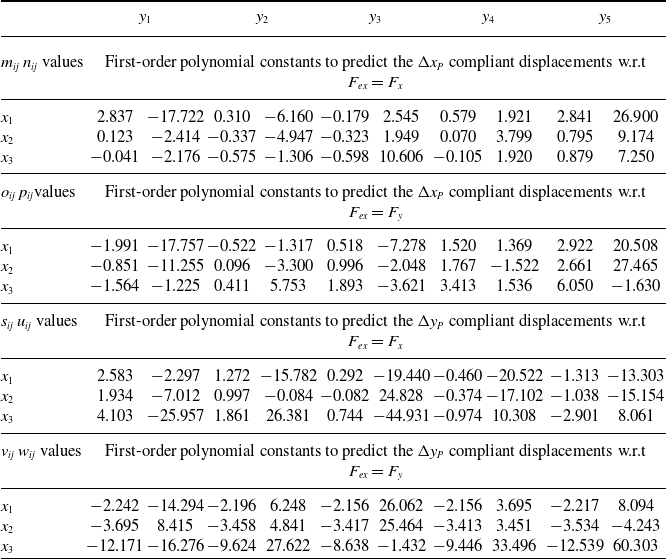
Appendix A. Polynomial constants for the relation between compliant displacements and forces
Polynomial constants for the 2-DoF over-constrained mechanism (actual constant
 $=$
given constant
 $x$
 $10^{-3}$
).

The compliance model parameters
 $m_{ij}$
,
 $n_{ij}$
,
 $o_{ij}$
,
 $p_{ij}$
,
 $s_{ij}$
,
 $u_{ij}$
,
 $v_{ij}$
, and
 $w_{ij}$
of the
 $\hat{Q}$
matrix given in Equation 12 are presented in Tables II and III for 2-DoF OC and NC mechanisms, respectively. Here, (
 $x_i, y_j$
) are the test locations defined for the tip point of the end-effector given in Figure 5. For each test location, there is a corresponding row matrix that includes two columns where the first column represents the linear part value and, the second represents the offset part value for the model parameters that are stated in the top-left corner of the sub-table, respectively. Since laser cutting is a noncontact operation, the measured path is not exactly the path of the tip point of the end-effector. There is a small offset (2.5 mm) between the tip point of the end-effector and the coated chipboards. The compliant displacements at the bottom and the top of the end-effector along its vertical axis are measured as explained in [Reference Paksoy, Dede and Kiper31]. With rigid-body assumption, the compliant displacements of the extended tip point, after 2.5 mm from the bottom of the end-effector along the axial axis, were calculated. Therefore, the corresponding compliance model parameters are derived from the compliant displacements of the extended tip point of the end-effector where the laser beam virtually contacts the coated chipboard. In Figure 5, the compliance model parameters
 $\hat{Q}$
are displayed with their
 $10^3$
amplified versions to be easily readable. The term ”w.r.t” is used for the abbreviation of ”with respect to” in Tables II and III.
Polynomial constants for the 2-DoF normal-constrained mechanism (actual constant
 $=$
given constant
 $x$
 $10^{-3}$
).

Appendix B. Electromechanical system
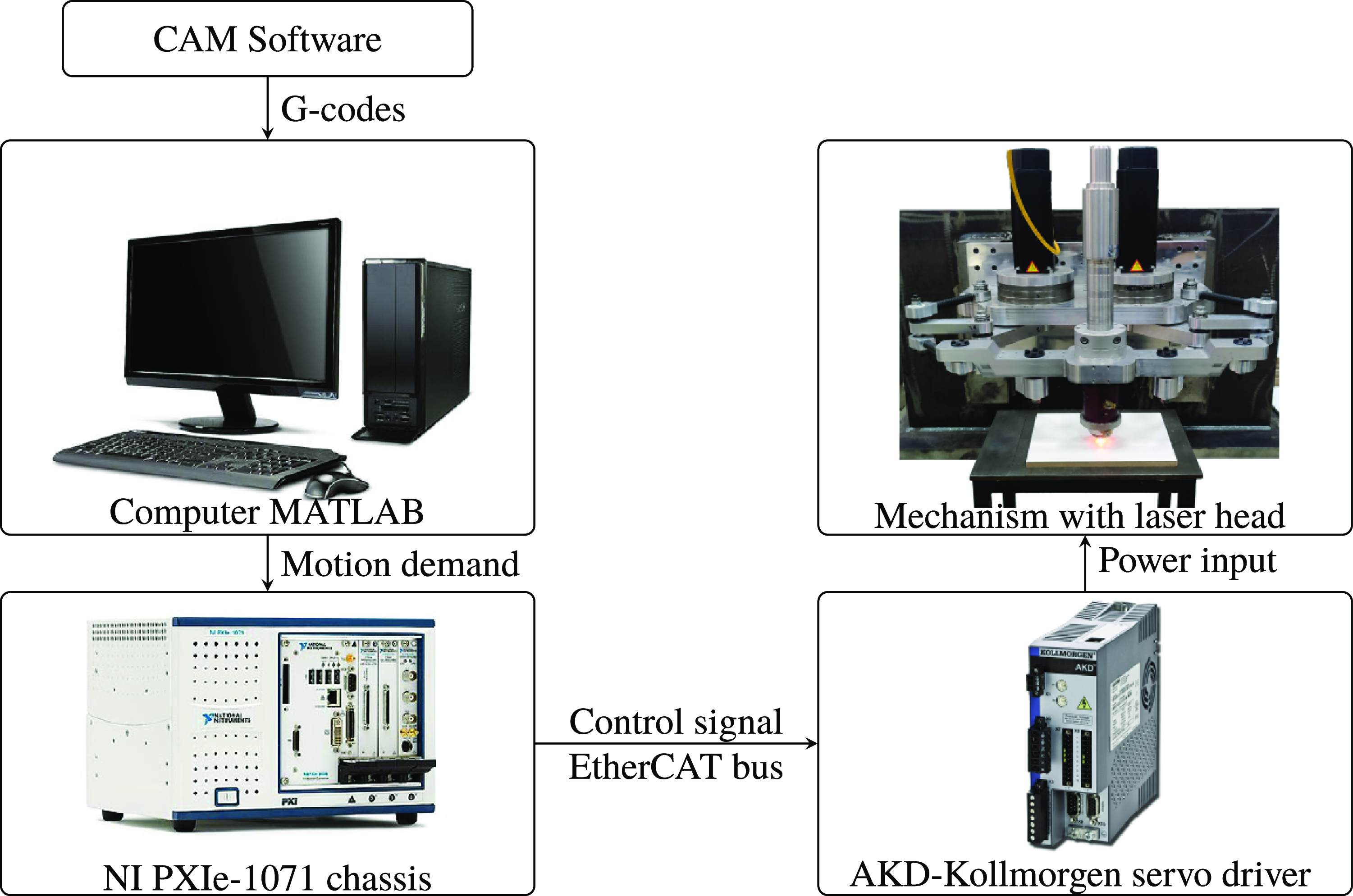
In Figure 18, the electromechanical system including the prototype of the 2-DoF over-constrained mechanisms with the laser marker head is depicted. The working principle of the mechanism is explained as follows: (i) by using a computer-aided manufacturing (CAM) software, defined paths are converted to G-codes, and these G-codes are transferred to the MATLAB software, (ii) according to the motion planning algorithm and kinematic equations, these G-codes are converted to the motion demands in terms of time-series data and sent to the National Instrument data acquisition (DAQ) system. (iii) By using the EtherCAT bus communication protocol, the motion demand for the actuators is converted to the control signal data and fed to the AKD-Kollmorgen servo drivers, (iv) as a result, the power input for the actuators is generated and transmitted. The laser marker system is operated by signals sent from the DAQ system. These laser marker-related signals are generated from the algorithm defined in MATLAB software.
Electromechanical system: hardware and software setup.

Appendix C. Detailed image processing algorithm for feature extraction
The image processing algorithm mainly calculates two features: the length between the start and end points of the marked paths to observe the deviation from the target distance, and the total area between the spline fitted to the captured path and the line fitted by minimizing the deviation of the captured path along the direction perpendicular to the fitted line to evaluate the captured path’s deviations from linearity.
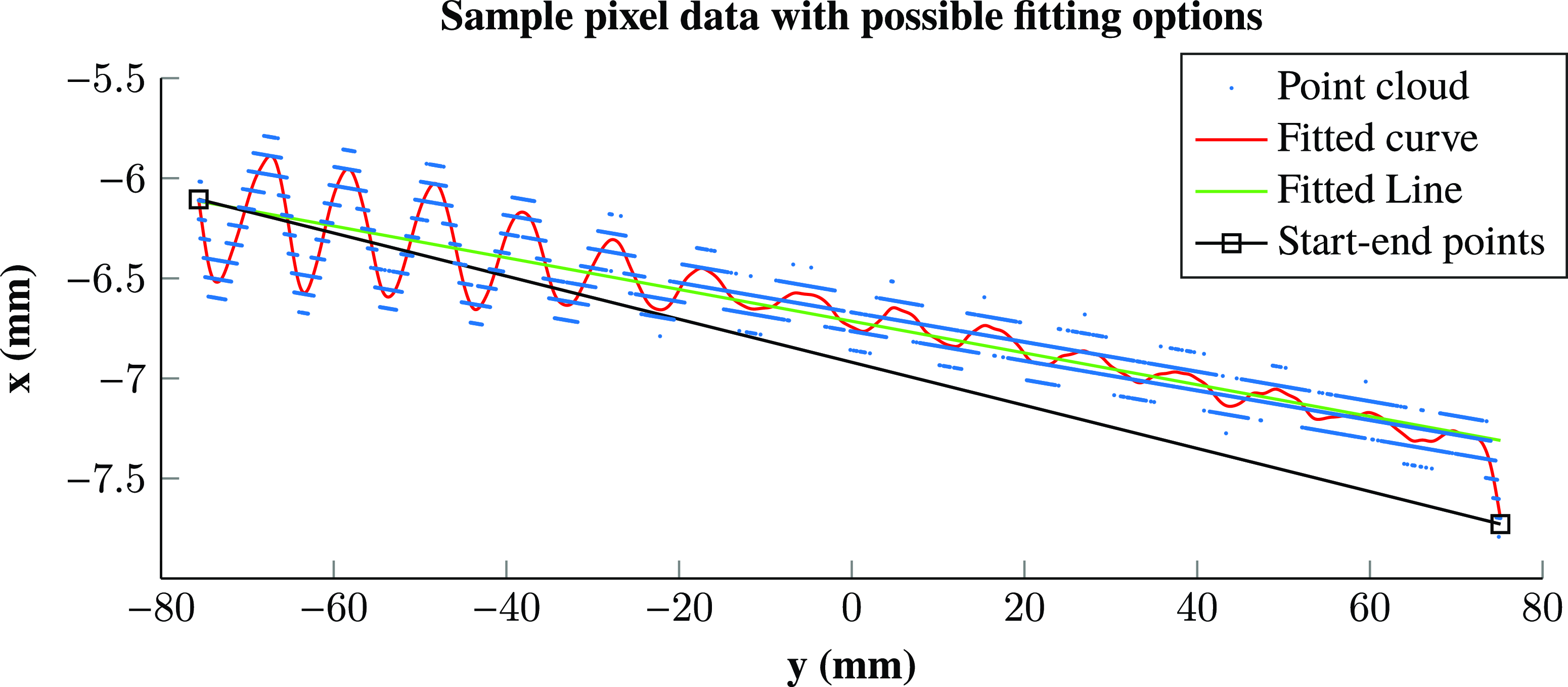
An example of the outcome of the aforementioned process which is explained in Section 5.3 until step (vi) for a test conducted at 5 g is shown in Figure 19. In step (iv), fitting a line or spline to the data is a minimization of the total error problem where the smoothing spline
 $s(x)$
is constructed by minimizing the following equation:
 \begin{align} p\sum _{j}^{}w_{j}(y_j-s(x_j))^2+(1-p)\int (\frac{d^2s}{dx^2})^2dx \end{align}
where
 $j=i, \ldots, f$
is pixel counter from initial pixel to final pixel,
 $p$
is smoothing parameter, and
 $w_j$
are specified weights.
For the fitted line,
 $p=0$
and
 $w_j=1$
are selected. When the smoothing parameter is
 $p=0$
, it produces a line of best fit which is a straight line that is the best approximation of the filtered path data. For the fitted curve (spline),
 $p=0.01$
and
 $w_j=1$
are selected. The smoothing parameter is chosen close to 0 because the marked path has minimal fluctuations along a straight line. The weights are specified as
 $w_j=1$
for both cases, which enforces that all of the data points are equally significant.
Image processing algorithm output.

As the first part of step (vi), the distance (
 $mm$
) between the start and end points of the path is calculated as the Euclidean distance
 $L$
as follows:
 \begin{align} L=\sqrt{(x_{f}-x_{i})^2 + (y_{f}-y_{i})^2}, \end{align}
where
 $(x_{i},y_{i})$
and
 $(x_{f},y_{f})$
specify the initial and final pixels of the filtered path, respectively (Equation C2). The values
 $y_{i}$
and
 $y_{f}$
are calculated by substituting the values of
 $x_{i}$
and
 $x_{f}$
to the fitted spline (curve) function as
 $y_i=s(x_i)$
and
 $y_f=s(x_f)$
, respectively. In the second part of step (vi), the total area (
 $mm^2$
) between the fitted line and the fitted curve is calculated to represent the amount of deviation from the designated path. For the total area calculation, let the fitted line equation be represented as
 $y=f(x)$
, and the fitted spline formula is given above as
 $y=s(x)$
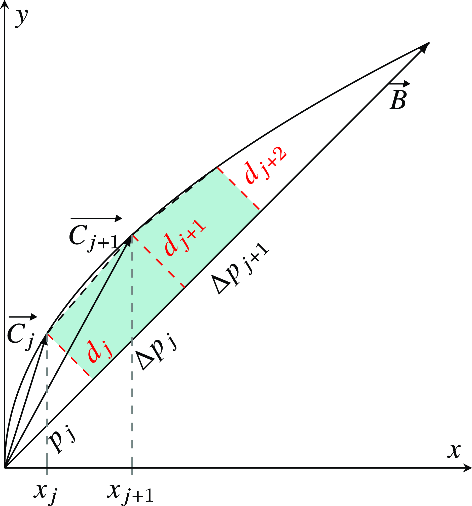
. Then, to specify the fitted line as a vector, a vector
 $\overrightarrow{B}=(x_{f}-x_{i})\boldsymbol{\hat{i}}+(f(x_f)-f(x_i))\boldsymbol{\hat{j}}$
is constructed. Then, a vector
 $\overrightarrow{C_j}=(x_{j}-x_{i})\boldsymbol{\hat{i}}+(s(x_j)-f(x_i))\boldsymbol{\hat{j}}$
is constructed to identify positions on the fitted spline corresponding to the equally spaced data points on the x-axis. The term
 $j$
is counter to represent the step size where the x-coordinates of the data points on the spline are equally spaced and
 $x_j$
corresponding to monotonically increasing x-coordinate values by equal increments while the counter
 $j$
is increasing.
As a next step, a perpendicular distance
 $d_j$
from a point
 $(x_j, s(x_j))$
on the spline to the fitted line is calculated as follows:
 \begin{align} d_j=\frac{\left \lvert \overrightarrow{B}\times \overrightarrow{C_j}\right \rvert }{\lvert \overrightarrow{B}\rvert }=\left \lvert \overrightarrow{C_j}\right \rvert sin{\alpha _j} \end{align}
where
 $\alpha _j$
corresponds to the angle between the vectors
 $\overrightarrow{B}$
and
 $\overrightarrow{C_j}$
. Correspondingly, the magnitude of the projection
 $p_j$
of the vector
 $\overrightarrow{C_j}$
on to the fitted line vector
 $\overrightarrow{B}$
can be calculated as follows:
 \begin{align} p_j=\frac{\overrightarrow{B}\cdot \overrightarrow{C_j}}{\lvert \overrightarrow{B}\rvert }=\left \lvert \overrightarrow{C_j}\right \rvert cos{\alpha _j} \end{align}
Representation of total area calculation.

The relative distance
 $\Delta{p_j}$
along the
 $\overrightarrow{B}$
vector which is defined between the perpendicular distances of
 $d_j$
and
 $d_{j+1}$
can be calculated as follows:
 \begin{align} \Delta{p_j}=p_{j+1}-p_{j} \end{align}
The total area of path-tracking error
 $A$
between the fitted curve
 $s(x)$
and fitted line
 $f(x)$
can be approximated as follows:
 \begin{align} A=\sum _{j=1}^{N-1}\frac{(d_j+d_{j+1})\Delta{p_j}}{2} \end{align}
where this calculation can be visualized as summing up the areas of the right trapeziums illustrated in Figure 20. The value of the
 $N$
is determined as
 $N=B_x/\rho$
where
 $B_x$
is the x-component of the
 $\overrightarrow{B}$
vector along the x-axis and
 $\rho$
is approximately 21.17
 $\mu m$
which is the pixel pitch of the 1200 dpi scanner. In order to verify the image processing algorithm, defined paths along the x- and y-axes (Figure 7a) are used. 100 mm length of
 $x$
motion and 150 mm length of
 $y$
motion are calculated as 99.98 mm and 150.08 mm, respectively.