1. Introduction
Unmanned aerial vehicles (UAVs) are used to perform numerous missions in areas like military, surveillance, patrolling, monitoring, agriculture, search and rescue, and delivery of essentials because of their low cost, high reliability, and better flight performance compared to manned aircraft [Reference Locascio, Levy, Ravikumar, German, Briceno and Mavris1–Reference Bhandari, Bettadapura, Dadian, Patel, Dayton and Gan4]. Furthermore, UAVs are a better alternative in scenarios deemed dangerous for manned aircraft like military operations in conflict-ridden environments as they do not endanger human life. This has led to an increased airspace demand which requires improved methods for assisting decision-makers and increasing operational efficiency in managing congestion. With UAV traffic expected to increase exponentially in the future [Reference Tsach, Peled, Penn, Keshales and Guedj5], deconfliction processes need to be executed in real time to minimize conflicts and assist airspace managers in optimizing airspace utilization.
Several studies have been conducted, and many methodologies concerning collision avoidance (CA) have been developed. Hoy et al. [Reference Hoy, Matveev and Savkin6] presented a survey of the various approaches regarding CA for mobile robots in complex environments. Diankov and Kuffner [Reference Diankov and Kuffner7] presented a randomized statistical path planning approach based on rapidly exploring random trees (RRTs) for efficiently controlling a robotic manipulator in a cluttered environment exploring the use of statistical learning methods on randomized path planning algorithms. Sanchez-Lopez et al. [Reference Sanchez-Lopez, Wang, Olivares-Mendez, Molina and Voos8] proposed a real-time path planning solution using an A* graph search algorithm to find a raw collision-free path. The use of graph-search algorithms provides good results but has significant limitations. This approach requires enough sampling space and a sufficient number of nodes before the start of the algorithm which makes it more suitable for initial path planning instead of real-time CA. Temizer et al. [Reference Temizer, Kochenderfer, Kaelbling, Lozano-Perez and Kuchar9] presented a CA model for unmanned aircraft based on partially observable Markov decision processes. The proposed approach can identify and generate new paths that are least deviated from the original flight plan and are free from collisions. It accommodates flight dynamics, intruder behavior, and sensor characteristics. Due to a large number of parameters, however, the state space is too large for many solvers, and therefore the solution is only presented for a two-dimensional (2D) model. Techniques based on geometric approaches are proposed by Strobel et al. [Reference Strobel and Schwarzbach10] and Park et al. [Reference Park, Oh and Tahk11]. One of the major issues with geometric techniques is that they depend on cooperation from intruder aircraft using sensors such as automatic-dependent surveillance-broadcast, and therefore they cannot work with non-cooperative obstacles. Furthermore, this makes them more susceptible to noise. Also, they do not offer good performance in the presence of multiple obstacles. Zhang et al. [Reference Zhang, Liniger and Borrelli12] demonstrated the use of optimization techniques to find the most suitable trajectory for CA models where the cost function is specified as the total distance traveled by the vehicle with no collision. One of the major issues with this approach is selecting the initial guess for optimization and the dependence of the final solution on these values leading to non-generalized solutions. Elmokadem and Savkin [Reference Elmokadem and Savkin13] proposed a trajectory planning method based on constrained multi-objective particle swarm optimization for robotic manipulators. However, optimization techniques are undesirable for real-time CA applications because of the high computational burden and therefore are generally preferred for trajectory pre-planning instead. Mehdi et al. [Reference Mehdi, Choe and Hovakimyan14] proposed piece-wise Bezier curves for avoiding collisions during multi-robot mission operations. Techniques such as this offer smoother trajectories but fail to satisfy assumptions and bounds on dynamic constraints such as position, velocity, and acceleration changes in some situations reducing the completeness of the approach.
Among several CA algorithms, the artificial potential field (APF) approach has been widely used for various autonomous systems. The concept of the APF was introduced by Khatib [Reference Khatib15] in which autonomous robots are attracted to the target location and repelled by the obstacles in their paths. This approach has been widely accepted and used for CA applications due to the simplicity of this idea. However, an agent based on the APF may be trapped in local minima situations and/or fail to reach the goal because of the algorithm’s limitations. In particular, the latter case is called the goal non-reachable with obstacles nearby (GNRON) problem. Plenty of studies have been performed for resolving these drawbacks. Some researchers proposed combining the APF with other algorithms. For example, the RRT is used as a global planner in the presence of only static obstacles to generate a path that does not encounter the local minima and GNRON, and then the APF is applied to the prior path [Reference Amiryan and Jamzad16]. Similarly, a bug algorithm [Reference Wang, Su, Tu and Lu17] is proposed to handle such issues for the APF in static obstacles’ existence environment. Park et al. [Reference Park, Kwak, Kang and Kim18] proposed an obstacle avoidance technique by combining the APF and fuzzy logic. While the attractive potential field used the existing form as it is, the repulsive potential field of the APF is replaced with the fuzzy inference system (FIS). However, this work mainly focuses on resolving one of the local minima issues. Others proposed modifying the attractive and/or repulsive potential functions in the APF. Some considered appending additional terms to potential functions. One of the examples is that rational and sinusoidal functions are added to the attractive and repulsive potential functions to resolve the GNRON and local minima issues, respectively [Reference Azzabi and Nouri19]. Also, additional functions by including signum functions are added to the repulsive potential function to resolve both issues [Reference Triharminto, Wahyunggoro, Adji, Cahyadi and Ardiyanto20]. These two studies considered static obstacles existence environment only. In other studies, the polynomial potential functions are replaced with the exponential functions [Reference Weerakoon, Ishii, Ali and Nassiraei21] and the Gaussian functions [Reference Cho, Pae, Lim and Kang22] in the presence of static and dynamic obstacles. Zhang et al. [Reference Zhang, Liu and Chang23] and Yang et al. [Reference Yang, Yang, Zhang, Chang, Chen and Zhang24] proposed the repulsive potential function multiplied by the relative distance between the agent and the goal as an additional term. To resolve the APF’s shortcomings, these papers considered static and non-cooperatively maneuvered dynamic obstacles. Pan et al. [Reference Pan, Li, Yang and Deng25] appended the relative distance between the agent and obstacles to the attractive and repulsive function for resolving the GNRON issue and an additional polynomial equation to the repulsive potential function that is designed to be activated in the local minima issue. In this case, only static obstacles are considered. Although avoiding collision among multi-robots for formation control in this research, it is different from the cooperative CA between an agent and dynamic obstacles. In addition to those studies, there is one more research that the concept of the APF is utilized for building FISs [Reference Sabo and Cohen26]. This study resolves the APF’s issues and shows that the proposed approach has better performance than the APF. However, this method does not guarantee better performance in the presence of dynamic obstacles. Vadakkepat et al. [Reference Vadakkepat, Lee and Xin27] proposed an evolutionary APF. The parameters of the APF are optimized with respect to the total path length using a multi-objective evolutionary algorithm. However, the parameters are optimized for only obstacles of equal size, and the simple environment with only one static or dynamic obstacle case is considered. Lee et al. [Reference Lee, Choi and Kim28] proposed a CA approach that combines the APF and motion primitives (MPs). When a collision checker detects collision risk on extracted sample points from the expected trajectory, replanned path candidates were generated. After rejecting unsafe route candidates, the APF to choose the best route among the remaining candidates was applied. Then, the MPs generated a locally optimal and dynamically feasible trajectory. Choi et al. [Reference Choi, Lee and Kim29] proposed an enhanced potential field (EPF) approach to resolve the local minima by introducing the concept of curl-free vector fields. This research focuses on generating smooth trajectories for dynamic obstacles compared to the APF rather than handling all the known issues of the APF. A critical factor that affects the performance of the APF and APF-based methods (e.g., path length, smoothness of the path, etc.) is the determination of the proper coefficients for designing the attractive and repulsive potential functions.
A fuzzy EPF (FEPF) system is proposed in this work to overcome the EPF’s drawbacks as the concept is intuitive and easy to realize. It comprises FISs that are used to determine the magnitudes of attractive and repulsive potential fields instead of using the potential function formulation in the EPF methodology. FISs allow for a scalable setup as the coefficients required for the magnitude determination for the potential fields in the conventional methods are not necessary anymore. The FISs are optimized to generate near-optimal trajectories for UAVs with a performance comparable to traditional methods. A genetic algorithm (GA) optimizes the parameters of the FISs as its meta-heuristic evolutionary nature makes it good at avoiding local optima and finding a near-optimal solution that minimizes the cost function. Combined, the genetic fuzzy system (GFS) is a method that provides results that are explainable when compared to traditional learning algorithms (e.g., neural networks and random forests) and outperforms the EPF approach. Furthermore, a FIS offers traceability in its approach providing a transparent workflow of the algorithm.
The main contributions of this work include the following:
-
• Resolve the GNRON and the local minima issues prevalent in traditional algorithms like EPF.
-
• Avoid the manual selection of coefficients in the EPF formulation for varying scenarios.
-
• Find a near-optimal trajectory for all UAVs in a specified region in the aspect of the travel distance.
-
• Offer a robust, scalable, and explainable learning approach that learns from a simple scenario and can handle complex environments.
This paper is organized as follows: Section 2 addresses the preliminaries defining the various concepts and techniques. Section 3 explains the methodology proposed. Section 4 defines the simulation scenarios and discusses the results. Conclusions are presented in Section 5.
2. Preliminaries
2.1. Problem statement
A set of simple and untraversable static obstacles defines a 2D environment spanning across an area of 300 m by 300 m. Other UAVs that travel through the region act as dynamic obstacles. The UAVs are not allowed to come within the thresholds of any of these obstacles. The safety threshold of these static and dynamic obstacles is defined in detail in Section 3.1.2. The environment outside the UAVs and obstacles is considered uniform and easy to traverse. Circular shapes of different radii represent the UAVs and static obstacles for simplicity. However, various-shaped static obstacles are considered for testing the proposed approach. Velocity limits are imposed for the UAVs to make the scenario more realistic. The optimality criterion for the GA is the distance traversed by the UAVs and is described in detail in Section 3.3.
2.2. Enhanced potential field
One of the most widely used algorithms for path planning and CA is the APF due to a simple principle and a smooth trajectory. The APF is composed of two potential fields: attractive and repulsive potential fields. While a goal attracts a UAV in the attractive potential field, obstacles repel the UAV in the repulsive potential field.
Since the EPF is designed based on the concept of APF, the attractive and repulsive potential functions are the same as APF and are defined as [Reference Khatib15,Reference Choi, Lee and Kim29–Reference Sun, Tang and Lao31]
 \begin{align} U_a({\bf q}) & = k_a d({\bf q},{\bf q}_g)^{n_a},\end{align}
 \begin{align} U_r({\bf q}) & = \begin{cases} k_r \left(\frac{1}{d\left({\bf q},{\bf q}_o\right)}- \frac{1}{{d}_o}\right)^{n_r}, & \ \ \text{if} \ \ d\left({\bf q},{\bf q}_o\right) \le d_o,\\ 0, &\ \ \text{if} \ \ d\left({\bf q},{\bf q}_o\right) > d_o, \end{cases}\end{align}
where
 $k_a$
and
 $k_r$
are the attractive and repulsive gain coefficients,
 $n_a$
and
 $n_r$
are the order of attractive and repulsive potential functions, q is the UAV’s current position vector,
 ${\bf q}_g$
is the goal position vector,
 ${\bf q}_o$
is the obstacle’s position vector,
 $d({\bf a}, {\bf b})$
is the relative distance between two arbitrary vectors a and b, and
 $d_o$
is the limit distance of the repulsive potential field influence.
The corresponding attractive and repulsive potential fields are obtained by computing the negative gradient of each potential function. Unlike the APF, the EPF introduces an additional variable, called a rotation matrix R, and the potential fields in the EPF are derived as follows [Reference Choi, Lee and Kim29]:
 \begin{align} {\bf f}_{a}({\bf q}) & = -\nabla U_a({\bf q}) = k_a n_a d({\bf q},{\bf q}_g)^{n_a -1} \frac{\partial d({\bf q},{\bf q}_g)}{\partial {\bf q}} , \end{align}
 \begin{align} {\bf f}_r({\bf q}) & = -\nabla U_r({\bf q}) = \begin{cases} -k_r n_r \left(\frac{1}{d\left({\bf q},{\bf q}_o\right)}- \frac{1}{{d}_o}\right)^{n_r -1}\frac{R}{d\left({\bf q},{\bf q}_o\right)^2} \frac{\partial d({\bf q},{\bf q}_o)}{\partial {\bf q}}, & \ \ \text{if} \ \ d\left({\bf q},{\bf q}_o\right) \le d_o,\\ 0, &\ \ \text{if} \ \ d\left({\bf q},{\bf q}_o\right) > d_o, \end{cases} \end{align}
where
 $\frac{\partial d({\bf q},{\bf q}_g)}{\partial {\bf q}}$
is the direction from the UAV to the goal location, and
 $\frac{\partial d({\bf q},{\bf q}_o)}{\partial {\bf q}}$
is the direction from the UAV to the obstacle. Since the repulsive potential field is generated for each obstacle, the total potential field for n obstacles is expressed as
 \begin{equation} {\bf f}_t = {\bf f}_a + \sum_i^n {\bf f}_{r_i}.\end{equation}
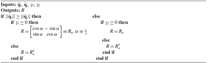
It is important to note that the direction of the repulsive potential field in the EPF is different from the one in the APF because of the rotation matrix. To determine the direction of the repulsive potential field, R is selected based on information of the speed (
 $||\dot{\bf q}||$
) of the UAV and the obstacle(s) and the relative angle (
 $\gamma$
) between the UAV and the obstacle(s). Note that obstacles can be either static (with zero speed like buildings) or dynamic (with certain speeds like UAVs). The direction of the repulsive potential field in the EPF is determined as described in Algorithm 1.
Direction determination algorithm

2.3. Genetic fuzzy system
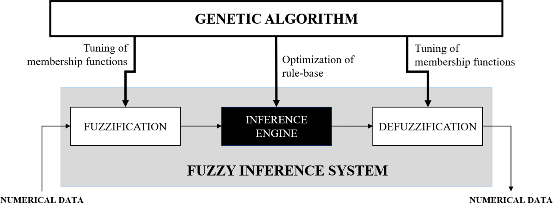
The GA is an evolutionary search algorithm inspired by Darwin’s theory of natural evolution [Reference Holland32], and a GFS utilizes the GA to optimize the parameters defining the FISs [Reference Goldberg33]. The GA aggressively searches throughout the specified search space for a near-optimal solution. A FIS is a system that maps the inputs to an output using the fuzzy set theory and a rule base [Reference Zadeh34]. The FISs used in this study are known as the Mamdani type of FISs [Reference Mamdani35], herein referred to as FIS. On feeding numerical inputs to the FIS, the FIS converts these values into fuzzy inputs by defining a degree of membership to each membership function (MF) for the numerical value. This process is known as fuzzification. The rule-based inference is then performed on these fuzzy inputs to obtain an output value that belongs to the output MFs with varying degrees of membership. After the inference, the fuzzy outputs are converted back into numerical values based on their membership value for each MF. Since the inputs may belong to multiple MFs, there can be more than one output with varying memberships. These are aggregated into a single fuzzy set by overlapping all the individual output fuzzy sets. The fuzzy output data then require defuzzification into numerical values to obtain proper values of the magnitudes of potential fields. The defuzzification method used in this study is called the centroid defuzzification method [Reference Ross36], and the numerical result is the centroid of the combined fuzzy set. However, the tuning of the FIS parameters using the GA is required, based on some pre-defined evaluation criteria, making the model more responsive to different kinds of situations that the individual UAV may encounter during a mission.
One of the primary advantages of this approach is that a FIS provides explainability in terms of linguistic description for the decision-making process. In addition to this, the aggressive search capability of the GA ensures that the solution is near-optimal. Fig. 1 represents a block diagram defining the basic process flow of a GFS. The tunable parameters of the FISs include the centers and edges of the MFs and the rule base.
Block diagram of a GFS.

3. Methodology
3.1. Fuzzy EPF model
3.1.1. Model definition
To adopt the FIS for CA, a new compact form of the potential fields that are composed of the magnitude and the direction is proposed:
 \begin{align} {\bf f}_a ({\bf q}) & = m_a \frac{\partial d({\bf q},{\bf q}_g)}{\partial {\bf q}},\end{align}
 \begin{align} {\bf f}_r ({\bf q}) & = m_r R \frac{\partial d({\bf q},{\bf q}_o)}{\partial {\bf q}}, \end{align}
where
 $m_a$
and
 $m_r$
are the magnitude of the attractive and repulsive potential fields, respectively. Equations (6) and (7) are used as new formulations of the FEPF, and the magnitude for each potential field is determined by fuzzy logic. Using these compact equations, the number of parameters to be determined is reduced from five (
 $k_a$
,
 $k_a$
,
 $n_a$
,
 $n_r$
, and
 $d_o$
) to two (
 $m_a$
and
 $m_r$
), and one can avoid trial and error to determine such parameters. Note that R is determined using the same criteria defined in Algorithm 1.
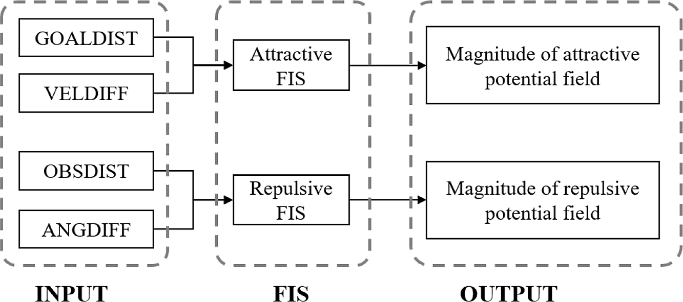
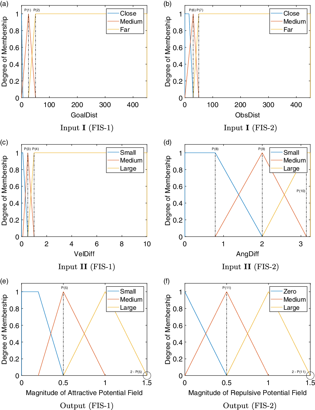
In this study, two sets of FISs are defined, and each FIS has two inputs and one output as shown in Fig. 2. To determine the magnitude of the attractive potential field, “GOALDIST” for the distance from the UAV to the goal location and “VELDIFF” for the velocity of the UAV relative to the goal location are used as inputs. In addition, “OBSDIST” for the distance from the obstacle to the UAV and “ANGDIFF” for the relative angle between the UAV and the obstacle are used as inputs to determine the magnitude of the repulsive potential field. When the number of obstacles is more than one, the repulsive potential field for a particular UAV is determined with respect to all the obstacles (see Eq. (5)). The goal distance is determined as the distance between the goal position and the center of the circular UAV minus the radius of the UAV since it has a fixed radius. The dynamic obstacles also have their own radii, and the obstacle distance is calculated as the distance between the centers of the UAV and the dynamic obstacle minus the radii of both the UAV and the dynamic obstacle. For each static obstacle, the nearest point on the obstacle from the UAV is selected to compute the obstacle distance. The velocity difference is determined as the relative velocity between the UAV and the goal, and the angle difference is defined as the absolute relative angle between the UAV’s velocity vector, and the relative position vector from the UAV’s position to the obstacle’s position. The range of all the inputs is defined in Fig. 3.
Structure of FISs.

MFs for FIS-1 (Attractive) and FIS-2 (Repulsive).

The inputs for the two FISs are chosen based on some knowledge of the existing EPF method. Figure 3 shows all the MFs for the inputs and outputs used in this work. The strength of the attractive potential field depends on the distance from the goal and the relative velocity difference, as the UAV must move towards the goal with maximum velocity and slow down as it approaches it. For the repulsive potential field, the ideal inputs are the relative distance and the relative angle to the obstacles allowing the UAVs to maneuver around the obstacles as they approach them. Furthermore, if the UAVs pass by the obstacles at a safe relative angle, they should maintain a safe distance. For simplicity, three MFs represent every input as the number of rules for a 2-input 1-output FIS is equal to
 $n \times m$
, where n and m are the numbers of MFs for each input. For three MFs representing both the inputs, there are nine rules. The purpose of a trapezoid MF (e.g., Far in Fig. 3b, Small in Fig. 3d, etc.) is primarily at the extreme ranges of the inputs and is generally defined using four parameters. A triangular MF (e.g., Medium in Fig. 3b, Medium in Fig. 3d, etc.) is more common in the non-extreme numerical range of an input/output, and three parameters represent such a MF. Note that fine-tuning some of the parameters that define these MFs (e.g., the centers and/or edges of each MF as shown in Fig. 3) is necessary to obtain better results. These parameters form the vector (
 $\bf P$
) used by the GA to find a near-optimal solution.
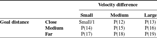
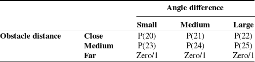
A matrix of if-then statements maps the respective inputs to the corresponding output forming the rule base of a FIS. Tables I and II show the rule matrices for both FISs. The rules can be represented linguistically in terms of the MFs using the examples given as follows:
-
• If GOALDIST is Close and VELDIFF is Small, then Magnitude of Attractive Potential is Small.
-
• If OBSDIST is Far and ANGDIFF is Large, then Magnitude of Repulsive Potential is Zero.
Rule matrix for FIS-1 (attractive).

Rule matrix for FIS-2 (repulsive).

Tables I and II contain the rule base of the two FISs. Although the rule base is composed of linguistic variables, such as Small, Medium, and Large, this work assigns numerical values to each linguistic variable for simplicity of the optimization process. The numbers 1, 2, and 3 represent the output MFs, that is, Small, Medium, and Large in the FIS-1 (Table I) and Zero, Medium, and Large in the FIS-2 (Table II), respectively. The vector P contains some of these rules alongside the MF parameters for the optimization process. The GA tunes the FISs by searching for the optimum value of the parameters in vector P within the defined search space (see Section 3.3). Figure 2 shows the structure of each FIS.
3.1.2. Uncertainties
Two kinds of uncertainties considered in this study are explained as follows. Using these measures of the uncertainties, thresholds are defined around the obstacles and UAVs which other UAVs may not enter. The threshold values are defined differently in both cases.
-
• Modeling Uncertainty: After training the model, there might be some scenarios where collisions may occur due to factors like non-optimal models and outliers. A probabilistic value in the range (0,1] represents the modeling uncertainty to compensate for such situations. In this study, a substantial stochastic value of 2/3 can accommodate most of the uncertainties. This value then defines the threshold (
 $\tau_1$
) as follows: (8)where the Max. Radius of UAV is set as 0.6 m.
\begin{align} \tau_1 = 2\times \text{Max. Radius of UAV} \times (1 + \text{Modeling Uncertainty}), \end{align}
-
• Environmental Uncertainty: After compensating the model for training uncertainties, there might still be a scenario with potential collisions due to environmental factors, such as unexpected gusts of strong winds and bad weather. The probabilistic value, in this case, is chosen to be 1 to compensate for worst-case scenarios. The threshold for this model (
$\tau_2$
) depends on both the environmental and modeling uncertainties as follows: (9)
\begin{align} \tau_2 = \tau_1 \times (1 + \text{Environmental Uncertainty}). \end{align}


From the above descriptions, the threshold values for the two models are 2 and 4 m, respectively, and the threshold values are applied to the proposed model in the training process.
3.2. Local minima problem caused by symmetric obstacle blocking
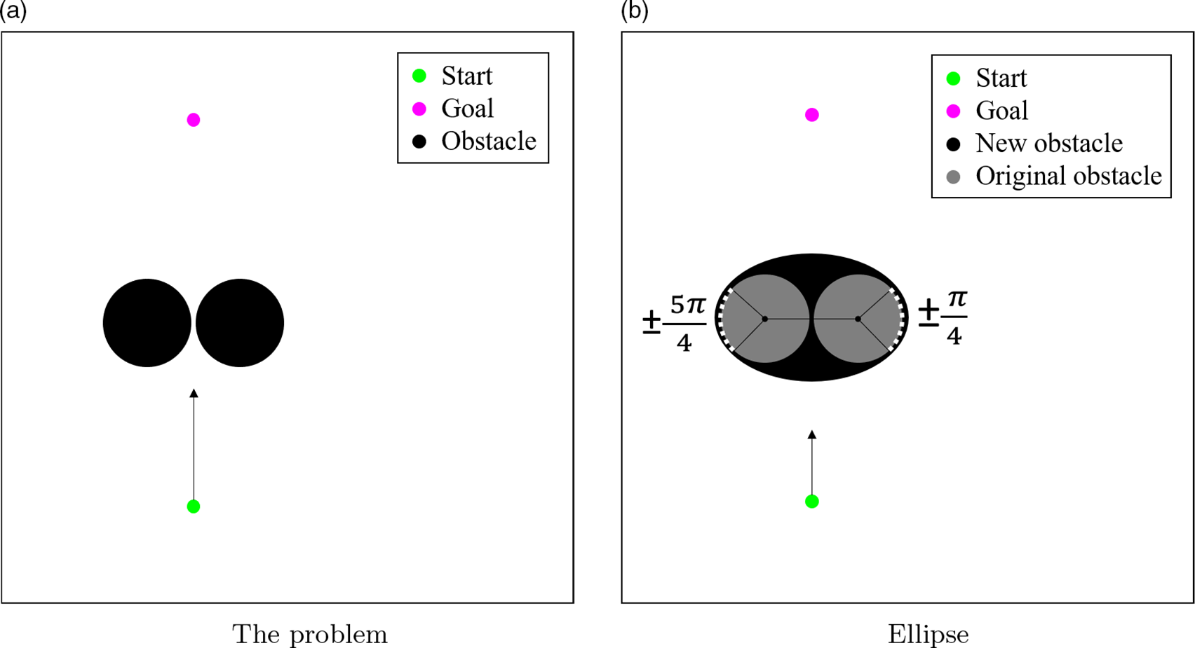
Consider a UAV is in a situation as depicted in Fig. 4a. It fails to find a trajectory around the obstacles as both obstacles have a different repulsive potential field pulling it close enough. In other words, the attractive potential field strength becomes equal to the net repulsive potential field strength, and they have opposite directions. Then, it eventually leads the UAV to get stuck. Although the FEPF can resolve this local minima issue, it is unfavorable in the aspect of the path length. For this reason, an algorithm to resolve such a situation is explained as follows:
-
• Get the enclosing points of the two obstacles as shown in Fig. 4b.
-
• Find the ellipse that fits those points using the least-squares estimation method [Reference Ohad37].
-
• Find an ellipse with slightly greater major and minor axes than the fitting ellipse to properly enclose the obstacles.
To obtain the set of enclosing points, a line is drawn between the centers of the two obstacles. The enclosing points are the points lying on the circular obstacles between
 $\pm\pi/4$
and
 $\pm5\pi/4$
angles, depending on the side. These angles are chosen concerning the connecting line as shown in Fig. 4b.
Solution to the local minima problem caused by symmetric blocking.

When the obstacles are close to the UAV, such that it cannot pass in between the obstacles, the UAV considers them a single obstacle. The shape of the new obstacle is the smallest ellipse that encloses both the circular obstacles. Figure 4b shows the result obtained using the suggested methodology.
3.3. Model optimization
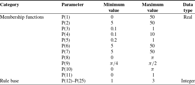
As mentioned in the previous sections, the GA is utilized to optimize the FISs in this work. The first step to implement the GA is to define the search space of the various parameters that are to be optimized. The GA heuristically then searches these spaces for optimal solutions. Table III contains the elements of P and their respective search regions.
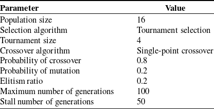
Table IV specifies the operational parameters for the GA. The GA terminates upon reaching the maximum generations or if the solution remains unchanged for a specified stall number. Here, the stall number is specified as half the maximum generations.
The evaluation criteria, or the fitness function for the GA, are defined as the total distance traveled by all the UAVs, and the GA aims to find a solution with the minimum fitness value. The fitness function (F) is formulated as
 \begin{equation} F = \sum_{i=1}^{n} d_i + \rho,\end{equation}
where
 $ d_i $
is the distance traveled by i-th UAV, and
 $ \rho $
is the penalty applied for undesired trajectories. The undesired trajectories include collisions between UAVs, collisions between a UAV and an obstacle, and the UAV traveling outside the specified region. Under such circumstances, large penalty values are applied to the fitness value.
Search space of the FIS parameters.

Operational parameters for the GA.

4. Simulation study
4.1. Simulation description
4.1.1. Training scenario
To tune the parameters of the proposed model, this work considers the following scenarios that are popular situations in the CA research field:
-
• Local Minima
-
• Aligned Obstacle - An obstacle presents exactly between the start position and the goal position of the UAV.
-
• Symmetric Blocking - Two obstacles symmetrically block the UAV’s path towards the goal location.
-
-
• GNRON - An obstacle presents really close to the goal location affecting the UAV’s ability to reach the goal.
-
• Dynamic Interaction - Multiple UAVs come from various directions and interact with each other in the presence of static obstacles, imitating a real-life interaction.
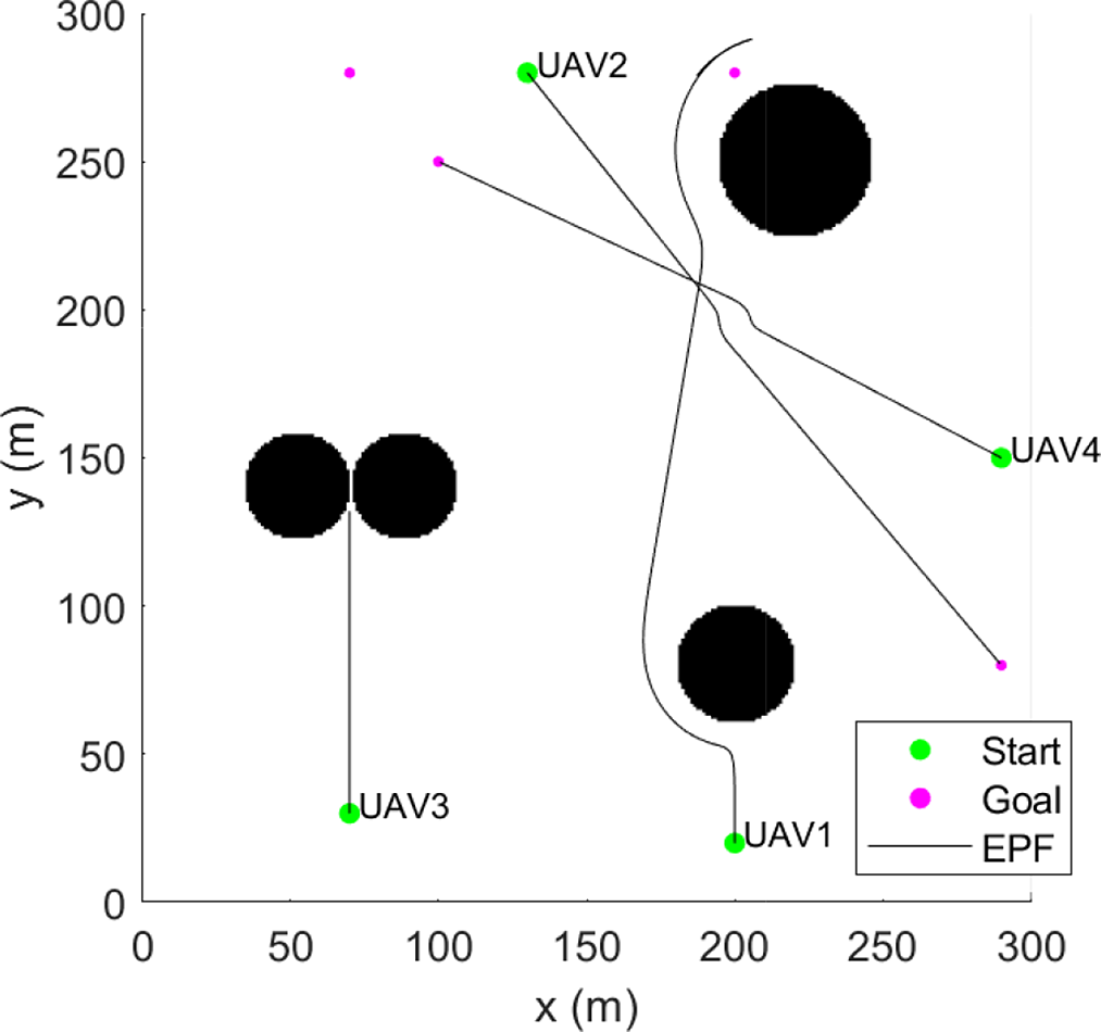
The above scenarios are modeled into a single training scenario with circular obstacles as shown in Fig. 5. UAV1 first encounters the aligned obstacle, one of the local minima cases, and then heads to the goal position that has the GNRON problem. UAV3 faces the symmetric blocking case, which is the other case of the local minima. Lastly, UAV2 and UAV4 interact with each other in the middle of their travels. To define the behavior for the UAVs, the speed and size of all UAVs are pre-defined as fixed values between some ranges. The radii of the UAVs are randomly selected within 0.2–0.6 m, and the average speed is also randomly chosen between 6.5 and 7.5 m/s. Note that the commercial drones’ specifications [38] are referred for determining the UAVs’ radii and average speed. For the information of the dynamic obstacles (the UAVs operating in the given airspace), the state information of other UAVs is known to the UAV because one assumes cooperative UAVs. In addition, this research assumes that the information of each static obstacle is known to the UAVs as a set of points about the outer edge of the obstacle, like a point cloud.
Training scenario with the resulting EPF trajectory.

The trajectories obtained using the EPF methodology are shown in Fig. 5. In this result, UAV1 escapes the local minima successfully. However, UAV3 and UAV1 fail to reach the goal location because of the limitations of the EPF. Due to such behavior, the training scenario consists of a combined model based on the above situations. For this scenario, the threshold values (
 $\tau_1$
and
 $\tau_2$
) are 2 and 4 m, as explained in Section 3.1.2, while the physical collision occurs at 1.2 m.
4.1.2. Testing scenarios
Using the optimized FEPF model, two types of testing simulation studies are defined. First, an environment with various shaped obstacles, such as triangular and U-shaped, is modeled for the UAVs to validate the robustness of the proposed approach.
The quick hull algorithm finds a convex hull of extreme points on the obstacle surface and forms polygons representing the U-shaped obstacles. The following steps define the process of the quickhull algorithm [Reference Barber, Dobkin and Huhdanpaa39]:
-
1. Find the points with minimum and maximum x coordinates and generate the line using two points to divide into two subsets of the given points.
-
2. Find the point with the maximum distance on one side of the line and make a triangle using the line and the point.
-
3. Repeat step 2 on the two lines formed by the triangle except for the initial line.
-
4. Repeat steps 2 and 3 until no more points are left.
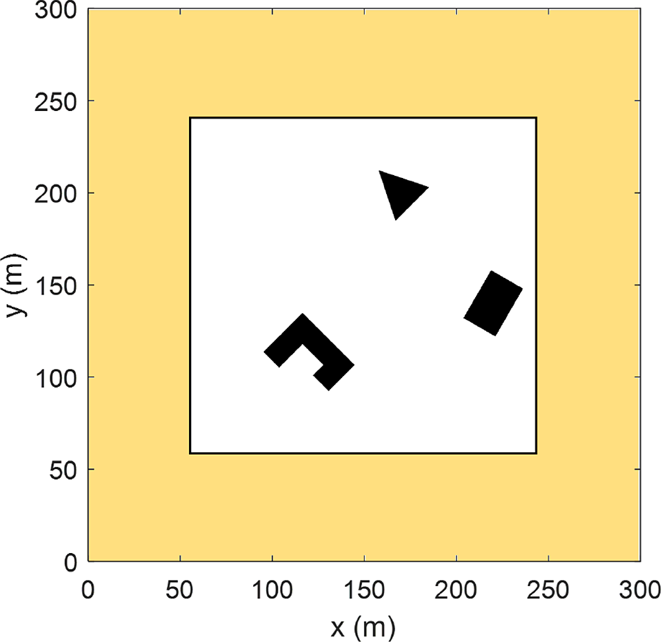
In the second testing study, several UAVs are operated within the same region to highlight the scalability of the proposed approach. The primary metric of comparison is the total path length of all the UAVs. As a prerequisite, Monte Carlo simulations are conducted with different amounts of UAV traffic to determine the necessary air traffic in the specified region for testing purposes. Start locations of up to 32 UAVs are generated randomly in a 300 m by 300 m obstacle-free area, depicted by the orange shaded region in Fig. 6. The UAVs travel to the opposite side of the airspace with a random velocity between 6.5 and 7.5 m/s. The number of UAVs in a specified area is calculated at each time to determine the number of active interactions. The maximum number of UAVs within a specified threshold of 4 m and the maximum number of UAVs inside the influence range of repulsive potential fields (defined as 30 m) are found as 4 and 14, respectively. Based on these results, the number of UAVs in the given airspace is selected. For a fair comparison between the approaches, the testing scenarios do not include the local minima and GNRON situations. Furthermore, to increase the number of interactions, the various shapes of static obstacles, such as triangles, rectangles, and convex shapes, are included. Moreover, both the EPF and FEPF approaches include the quick hull algorithm for a fair comparison. Simulations are conducted in testing scenarios with 4–14 UAVs (incrementing by 2) to validate the performance of FEPF against EPF, leading to a total of six different testing simulations. For a precise comparison, 100 randomized simulations for each of these test environments are conducted, leading to a total of 6
 $\times$
100
 $=$
600 different scenarios for comparison. These different scenarios have different start and goal positions located within the highlighted (orange) area in Fig. 6.
Testing environment.

4.2. Results
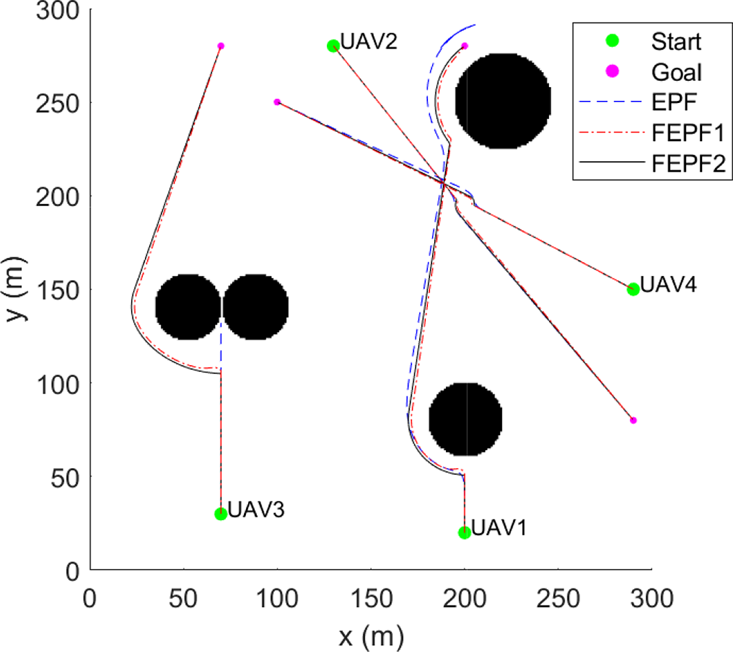
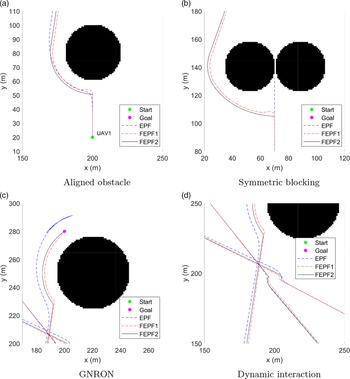
The results using the FEPF tuned by the GA are compared to the results using the EPF approach to validate the performance of the proposed method. The 2D trajectories of UAVs for the training scenario are described in Figs. 7 and 8, and the trajectories obtained using the EPF and the FEPF approaches considering uncertainties are overlapped. Note that the FEPF1 and FEPF2 are the FEPF using
 $\tau_1$
and
 $\tau_2$
, respectively. As shown in Fig. 7, the FEPF approach avoids static and dynamic obstacles and reaches goal locations successfully. In Fig. 8, the detailed trajectories for each approach are described. Since the FEPF1 is trained using a smaller threshold value than the FEPF2, the FEPF1 performs the avoidance maneuver closer to obstacles compared to the FEPF2.
Total path length and minimum relative distance for each approach.

Total path length for each approach of 4 and 8 UAVs cases.

2D trajectories of training scenario for the EPF and FEPF.

Detailed trajectories of training scenario.

Testing results in the presence of various-shaped obstacles.

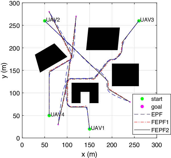
To validate the performance of the proposed approach, obstacles with different shapes, such as a trapezoid, parallelogram, rectangle, and U-shape, are used in the first testing scenario. Both EPF and FEPF use the quickhull algorithm to model U-shaped obstacles for a fair comparison. Figure 9 shows the 2D trajectories for each approach. The FEPF1 trajectory maintains a closer relative distance from the obstacles compared to the EPF and FEPF2 approaches. The total path lengths and the minimum relative distances for all the approaches given in Table V show that FEPF1 provides the shortest path, and the UAVs using FEPF1 avoid the obstacles with a smaller relative distance as shown in Fig. 9.
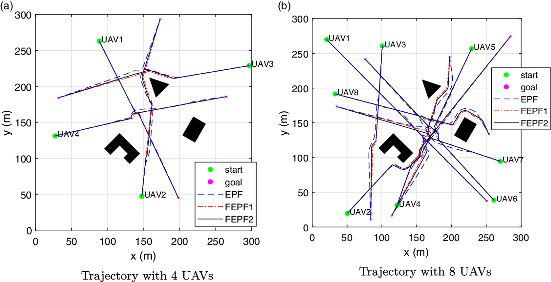
In the second testing scenario, 600 simulations (100 for each case with 4, 6, 8, 10, 12, and 14 UAVs) with random start and goal positions are performed. As a result of 100 tests for each case, it is found that no collisions occur for any method. Among the test results, the cases where 4 and 8 UAVs cooperate are selected to display as shown in Fig. 10 to highlight the path difference. Like the training results, it is found that the trajectories produced by the EPF are longer than the trajectories of the FEPF1 and FEPF2. The obtained total path length for the EPF, FEPF1, and FEPF2 is listed in Table VI. As expected, the FEPF1 has the shortest path length among the approaches.
Testing results for 4 and 8 UAVs.

Testing results for FEPF1.

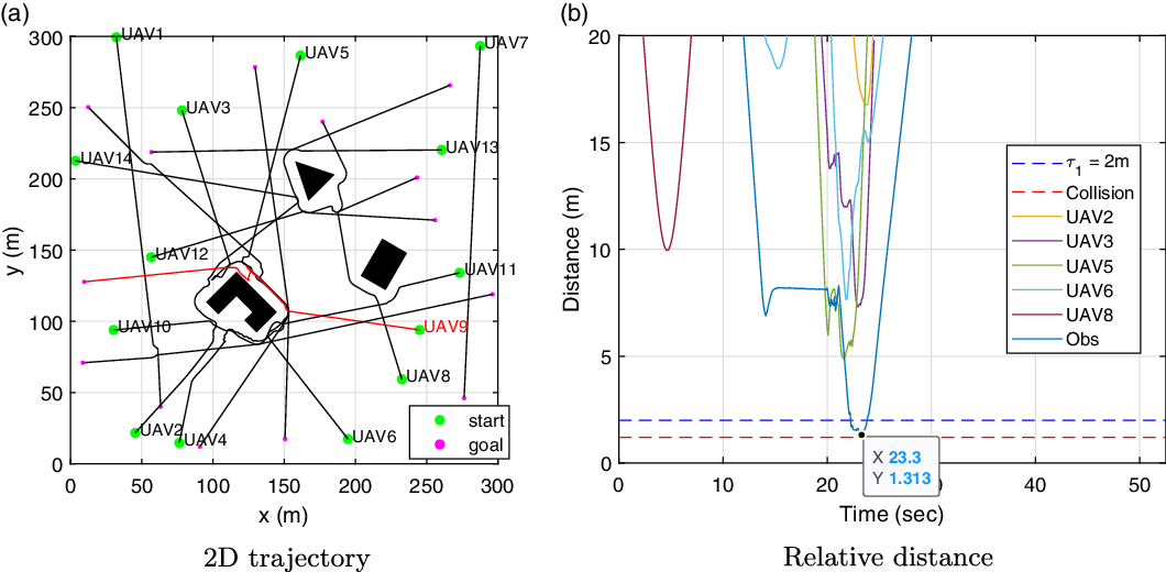
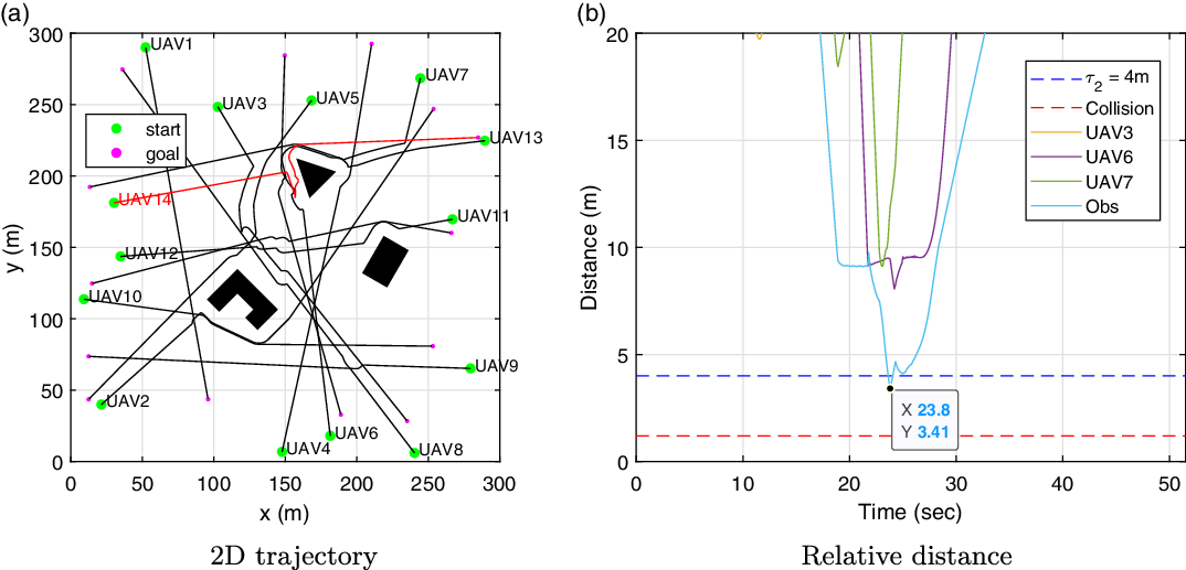
For the case where 14 UAVs cooperate, one of the results that have the closest relative distance between the UAV and obstacles is displayed in Figs. 11 and 12. The red line in Figs. 11a and 12a highlights the trajectory of the UAV that has the closest relative distance from the obstacles. Although UAV9 in Fig. 11a and UAV14 in Fig. 12a detour near the static and dynamic obstacles, both UAVs successfully avoid collision and reach the goal position. In Figs. 11b and 12b, the relative distances between the obstacles and the UAV with the red line in Figs. 11a and 12a are displayed as 1.31 and 3.41 m, respectively. Note that the blue and red dotted lines indicate the threshold and physical collision, respectively. If the relative distance is larger than the threshold, the UAV performs the CA maneuver safely, and the UAV collides with an obstacle when the UAV has a smaller relative distance than the red dotted line. If the UAV has a relative distance between the blue and red dotted lines, there is a possibility for the UAV to have potential collision risk because of uncertainties, but it still avoids obstacles successfully. Since both cases keep the relative distance larger than the physical collision value, it confirms that all UAVs avoid obstacles without collision. Although the FEPF2 has a large threshold value for considering two kinds of uncertainties, it may have potential collision risk in the complex environment that there are a greater number of static obstacles and UAVs in airspace than one considering in this research.
Testing results for FEPF2.

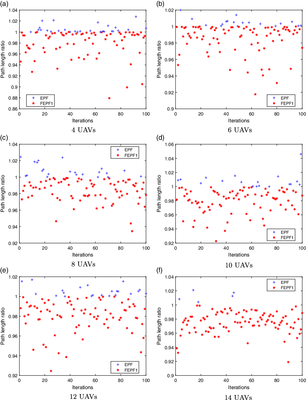
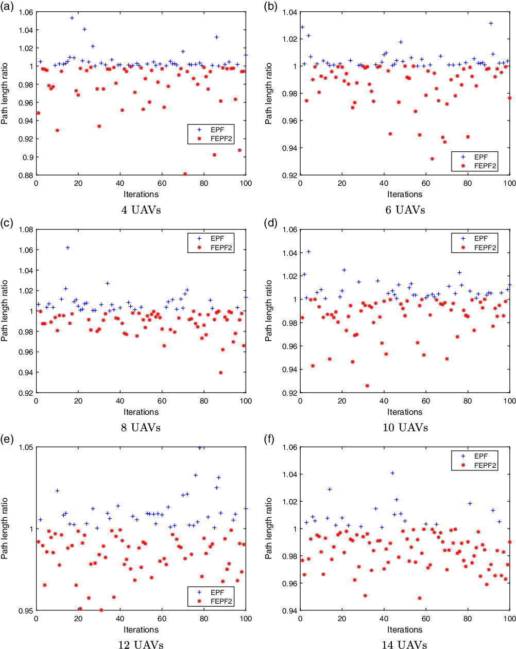
To validate the performance of the proposed approach, the path length ratio between the EPF and the FEPF is considered, and the results are shown in Figs. 13, 14, 15, and 16. Note that the path length ratio is calculated by
 \begin{equation} \text{Path length ratio} = \frac{\text{Total path length of UAVs generated by the FEPF}}{\text{Total path length of UAVs generated by the EPF}}.\end{equation}
Path length ratio for EPF and FEPF1.

Path length ratio for EPF and FEPF2.

Average path length ratio differences for FEPF1 and FEPF2.

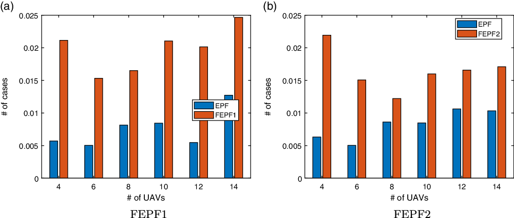
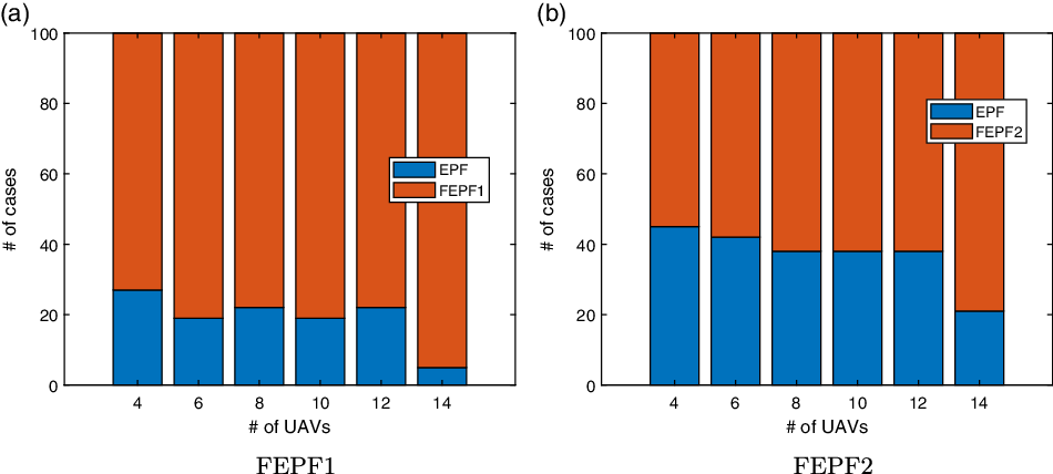
Number of the better performed cases.

This equation means that the path length ratio is under 1 when the FEPF has a shorter path length than the EPF. Also, the average path length ratio differences in Fig. 15 are the average value of the differences from 1. Here, an approach with a larger path length ratio has a shorter path length. In Fig. 16, a comparison of the number of cases that have better performance (i.e., a shorter path length) for each approach is displayed. As shown in the results, the FEPF approaches have a shorter path length than the EPF overall. Between the FEPF1 and FEPF2, the FEPF1 has more cases that have a better performance than the FEPF2 as shown in Fig. 16. In addition, the FEPF1 provides a shorter path length compared to the FEPF2 because the threshold value of the FEPF1 is smaller than that of the FEPF2.
5. Conclusion
This research proposes a novel approach to provide shorter, local-minima-free, and GNRON-free CA trajectories. The proposed approach is named the fuzzy EPF, simply called FEPF, since it combines a FIS and the EPF. The magnitudes of attractive and repulsive potential fields are determined using the FIS, while their directions are determined by the determination criteria of the EPF. Two FISs are utilized for the FEPF, and the MFs and the rule base of the FEPF are optimized by a GA to find the near-optimal solution in the aspect of the total path length of the UAVs. In the training process for optimizing the FEPF, the training scenario is selected by containing local minima, GNRON, and interactions between UAVs in one scene. For the consideration of safety, modeling and environmental uncertainties using a probabilistic value are additionally considered, and two kinds of FEPF models are defined with respect to the degree of uncertainties. Consequently, it is shown that both FEPF models outperform the EPF in the aspect of the average path length and the number of cases that have shorter paths. Also, it is confirmed that the FEPF model trained with the smaller threshold value provides a relatively shorter path. This indicates that lesser uncertainties guarantee a shorter path. More importantly, in addition to the good performance demonstrated by the proposed approach, it also offers explainability using a rules-based inference system, scalability by offering to not select parameters manually as the problem changes, and robustness by performing better than traditional techniques in a number of different scenarios that include uncertainties. Currently, the proposed algorithm is developed in 2D environments without considering UAV dynamics. Future works will include 3D environmental simulations with complete dynamic modeling of UAVs as well as experimental validation. Furthermore, the training process will take into account irregular obstacles and sensing constraints.