Introduction
Laser material processing is an emerging and promising technique because of its simplicity, non-contact procedure, precision, repeatability, and flexibility (Yaseen et al., Reference Yaseen, Bashir, Shabbir, Jalil, Akram, Hayat, Mahmood, Haq, Ahmad and Hussain2016). Laser–matter interaction is responsible for the ejection of ablated species in the form of electrons, ions as well as neutral atoms due to various thermal, physical, chemical, and mechanical processes (Miller, Reference Miller1997). It is therefore, important to understand the underlying processes governing laser ablation mechanisms. The measurement of sputtering yield of laser-ablated target is highly important for thin film deposition, laser-induced plasma formation, ion implantation as well as micro/nano structuring of materials. For sputtering yield measurement, various experimental techniques are proposed (Muenster et al., Reference Muenster, Welle, Ridder, Althuon, Striffler, Foertsch, Hahn, Thelen, Stadler and Nesterov-Mueller2016), ion probes, Faraday cups, laser-induced fluorescence, quartz crystal microbalance (QCM) (Boyadjiev et al., Reference Boyadjiev, Georgieva, Stefan, Stan, Mihailescu, Visan, Mihailescu, Besleaga and Szilágyi2017), and time of flight mass spectroscopy (Yar et al., Reference Yar, Ali and Baig2013).The QCM is a device with wide range of applications in surface science and related disciplines for mass measurements in the nanogram range and its working is based on the piezoelectric effect (Qiao et al., Reference Qiao, Zhang, Tian and Meng2016). The resonance frequency of the quartz crystal depends upon its mass, temperature, stress, and the exact position of the deposited material and is independent of the nature of material. By keeping all factors constant other than mass, the change in resonance frequency can be measured. The ablation sensitivity is attributed to location-dependent sensitivity of QCM which is maximum in center and decreases as the radial distance from center is increased (Cumpson and Seah, Reference Cumpson and Seah1990). Such a setup can provide important pulse-resolved information to improve the understanding of laser-induced breakdown spectroscopy and pulsed laser deposition, where the knowledge of the ablated material deposited per pulse is highly desirable for the interpretation of deposition rate and plasma formation (Gierse et al., Reference Gierse, Schildt, Esser, Sergienko, Brezinsek, Freisinger, Zhao, Ding, Terra and Samm2016).
Fe is a transition metal and is significantly important in material science because of its chemical activity, high ductility, malleability, high tensile strength, and ferromagnetic nature at room temperature. The sputtering yield of iron reported in literature is about 1015 atoms/cm2 (Behrisch et al., Reference Behrisch, Roth, Bohdansky, Martinelli, Schweer, Rusbüldt and Hintz1980). The work related to sputtering yield measurement of Fe as a function of laser fluence and gas pressure under different ambient environments is scarcely reported. The effect of pressure and nature of ambient gas play a crucial role in energy deposition on the target and its sputtering yield (Bashir et al., Reference Bashir, Khurshid, Akram, Ali, Ahmad and Yousaf2015). As compared with femtosecond laser, nanosecond laser irradiation is responsible for higher ablation yields due to enhanced photothermal effects (Kanitz et al., Reference Kanitz, Hoppius, Del Mar Sanz, Maicas, Ostendorf and Gurevich2017).
In the literature, the sputtering yield measurements of Nd: YAG-ablated iron by QCM are not reported. However, Gibert et al. (Reference Gibert, Dubreuil, Barthe and Debrun1993) investigated laser sputtering of iron using resonance ionization mass spectrometry. They employed N2 laser with a wavelength of 337 nm, pulse duration of 10 ns at a fluence of 320 mJ/cm2. A maximum of 6 × 10⁷ atoms per laser shot were emitted during their study. Lunney and Jordan (Reference Lunney and Jordan1998) studied excimer laser (λ = 248 nm and 26 ns pulse duration) ablation of iron with the help of weight loss method by weighing the target before and after laser ablation. The reported ablation rate of iron at 4.5 J/cm2 was 6 × 1024 atoms/cm/s. Therefore, sputtering yield measured by QCM of the order of 1015 atoms per laser shot in the present experiments by employing Nd: YAG laser (532 nm, 6 ns, 10 Hz) at various fluences ranging from 4.8 to 38.5 J/cm2 can be compared with the previously reported work. Svendsen et al. (Reference Svendsen, Ellegaard and Schou1996) studied the deposition rate of metals, that is, silver and nickel on QCM as a function of laser wavelength, position, fluence, and gas pressure. It was observed that the deposition is higher for 532 nm than 355 nm. With the increase of ambient gas pressure, a decrease of deposition rate was observed.
The objective of the present work is to propose an optimized combination of laser fluence and ambient gas pressure at which maximum sputtering yield of laser-ablated Fe under different reactive (O2 and air) and non-reactive environments (Ar and Ne) is obtained. Then these sputtering yield measurements probed by QCM are correlated with surface structuring explored by scanning electron microscopy (SEM) analysis. Laser ablation of materials has widespread technical applications with broad range of aspects and parameters that have been investigated and reported previously by many research groups. However, the novel aspect of the present work is to illustrate the comprehensive and detailed study to investigate the effect of laser fluence as well as environmental conditions on both the sputtering yield and surface structuring of iron. Iron is a less investigated material regarding laser ablation due to its highly reactive nature. Iron is a widely used metal in electronics, manufacturing, automotive, construction and building. In the previously reported work, the sputtering yield measurements of metals are widely reported. On the other hand, laser-induced surface structuring of metals is also extensively investigated. But correlations of sputtering yield with surface structuring is scarcely reported, which is important for laser-assisted ablation, deposition, ion generation, and implantation experiments. Similarly no work is reported in which it is investigated how the laser fluence and different gases along with their masses and ionization potentials can be considered to be responsible for ablation yield and growth of surface structures on any metallic target.
The depth of the ablation crater has also been measured from surface profiles using optical microscopy analysis.
Experimental setup
Second harmonic (λ = 532 nm) of Q-switched Nd: YAG laser (Quantel 981C) pulses with 6 ns pulse duration and repetition rate of 10 Hz has been employed to ablate the Fe target. Square-shaped commercial iron (96.91% Fe) samples with dimensions of 2.5 cm × 2.5 cm × 0.5 cm were cut, grinded, and polished using different grades of silicon carbide papers. The samples were then ultrasonically cleaned for 10 min in an acetone bath. The targets were placed on a rotating sample stage which was slowly rotated with the help of a stepping motor to provide a fresh surface exposure to each laser pulse which is necessary to avoid non-uniform pitting and crater formation due to successive laser pulses. The chamber was then evacuated to the base pressure of 10−3 Torr with the help of rotary pump. The laser beam was focused at an angle of 45° with respect to the target surface using a focusing lens of 50 cm focal length. The target was placed at a distance of 1 mm before the focus point to minimize the gas breakdown.
The mass deposition rate was measured by QCM (QCM 200 Quartz Crystal Microbalance Digital Controller, SRS. Inc., USA). The continuously oscillating quartz crystal acting as a substrate was mounted parallel to target surface at an optimized distance of 3 cm from the target surface. The quartz crystal mounted on the crystal holder was connected to the 5 MHz crystal oscillator (QCM 25) in order to keep the crystal oscillating at a constant frequency. The controller is used to detect any mass changes, that is, deposition onto the front electrode by the change in the oscillation frequency of the quartz crystal.
Following two sets of experiments were performed. In the first set of experiments, both the sputtering yield as well as deposition rate of Fe were measured as a function of laser fluence. For this purpose, the Fe targets were exposed to 100 accumulative pulses of Nd: YAG laser with a spot size of 1000 µm, at eight different fluences of 4.8, 9.6, 14.5, 19.3, 24, 28.9, 33.7, and 38.5 J/cm2 corresponding to laser pulse energies ranging from 40 to 320 mJ. These fluences were varied by varying the pulsed energy of laser beam measured by energy meter. Their corresponding laser irradiances are 0.8, 1.6, 2.4, 3.2, 4, 4.8, 5.6, and 6.4 GW cm−2. In order to explore the effect of background gases along their corresponding pressures on the sputtering yield/deposition rate of Fe, all the measurements were performed under different reactive and non-reactive environments like vacuum, Ar, Ne, O2, and air (combination of O2 and N2). In order to explore the effect of pressure of these environmental gases, all the measurements of deposition rate/sputtering yield were performed under five sets of pressures, that is, 5, 10, 20, 50, and 100 Torr for all background gases.
In the second set of experiments, the targets were exposed to 100 pulses of Nd: YAG laser for SEM analysis. For this purpose, four fluences of 4.8, 14.5, 24, and 33.7 J/cm2 were selected and targets were exposed under vacuum as well as under different ambient environments of Ar, Ne, O2 and air at a fixed pressure of 5 Torr. The surface morphology and energy-dispersive X-ray spectroscopy (EDX) analyses were performed by using SEM (JEOL JSM-6480 LV). The crater depth of exposed Fe target was explored by using an optical microscope (STM-6 Olympus) controlled by DPS-2 software. The crater depth was measured for the same parameter as have been used for SEM analysis. For the compositional analysis of the laser-irradiated Fe samples, XRD analysis was employed. For this purpose, X′ Pert PRO (MPD) X-ray diffractometer was used.
Results and discussion
Sputtering yield measurements of laser-ablated Fe by QCM
The mass deposited at the quartz crystal is calculated by using the Sauerbrey equation (Sauerbrey, Reference Sauerbrey1959; Gierse et al., Reference Gierse, Schildt, Esser, Sergienko, Brezinsek, Freisinger, Zhao, Ding, Terra and Samm2016).
 $$\Delta f = -C_{\rm f}\Delta m$$
where Δf is the change in frequency which is experimentally measured, Δm is the mass deposited, and C f is the sensitivity factor of crystal and its value is 56.6 Hz/μg. The total ablation yield Y is calculated from the mass deposited on a QCM at the distance r = 3 cm from the Fe target surface with an angular distribution of cosnθ. As QCM is placed parallel to target, cosnθ becomes equal to 1 (Svendsen et al., Reference Svendsen, Ellegaard and Schou1996).
 $$Y = 2{\rm \pi} r^2\mathop \int \limits_0^{{\rm \pi} /2} D({\rm \theta} )\sin ({\rm \theta} )d{\rm \theta} $$
 $$Y = 2{\rm \pi} r^2\displaystyle{{D(0)} \over {n + 1}}$$
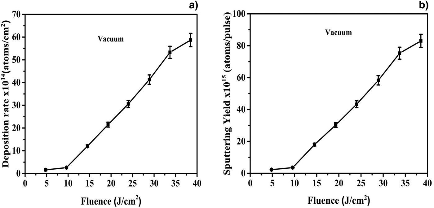
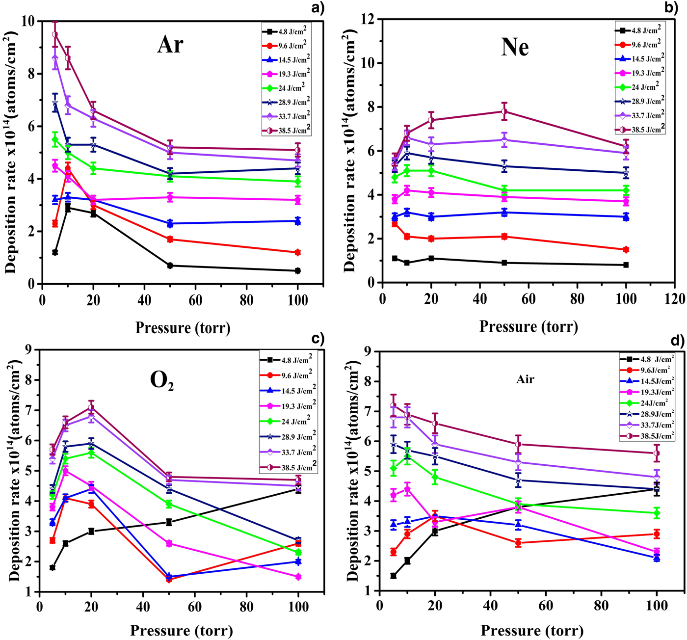
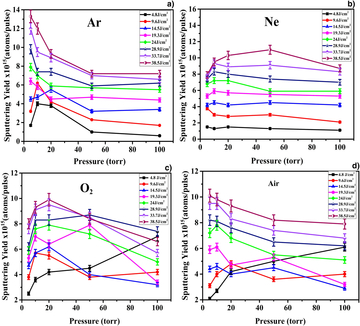
where D (θ) is the area density of the deposited material along the direction of the angle θ with respect to the target surface normal. In our case, as the deposition rate is measured in cm−2, thus the D (0) is equal to the mass deposited in QCM. The value of n = 3 is taken from Kool's analysis (Kools et al., Reference Kools, Van De Riet and Dieleman1993). According to this analysis, the value of n = 3 corresponds to the low value of laser spot diameter, that is, slightly <1 mm for single shot. In our case, the value of laser spot for 100 pulses is 1.03 mm, which is comparable to the values reported by Kool (Kools et al., Reference Kools, Van De Riet and Dieleman1993). The deposition rate per pulse and sputtering yield of laser-ablated Fe as a function of laser fluence under vacuum condition measured by QCM are revealed in Fig. 1a and 1b, respectively. These graphs reveal that both mass sputtered per pulse and mass deposition rate lineally increase as the laser fluence increases. However, at the highest fluence, this trend becomes non-linear. The graphs of Figs 2 and 3 show the variation in deposition rate and sputtering yield of Fe under different reactive and inert ambient environments of (a) Ar, (b) Ne, (c) O2 and (d) air measured by QCM at various laser fluences ranging from 4.8 to 38.5 J/cm2. The graphs of Figs 2a and 3a are related to Ar environment and reveal the deposition rate and sputtering yield of laser-ablated Fe as a function of laser fluence, respectively. They exhibit two fluence regimes as a function of pressure of gas, that is, low- and high-fluence regimes. In the low-fluence regime, both deposition and sputtering yields initially increase and then achieve a maximum value which is under 10 Torr pressure of Ar. They show a decreasing trend with further increase of pressure up to 50 Torr and afterwards they saturate. In the higher fluence regime, both parameters tend to decrease monotonically with increasing pressure up to 50 Torr. For the pressure range from 50 to 100 Torr, insignificant changes in sputtering yields are observed with saturation behavior. These graphs of Fig. 3a–3d reveal that laser fluence is the key parameter for controlling sputtering yield of Fe. By increasing laser fluence, the sputtering yield of Fe increases irrespective of the environmental conditions. However, this variation is different in different gases as well as under different pressures. At low pressure, more pronounced variation of sputtering yield of Fe with laser fluence is observed in Ar, than air and O2, whereas, least variation is observed in Ne. But under higher pressures, the sputtering yield variation becomes more pronounced in Ne than other environments. It is observed from the comparison of graphs of Fig. 3a–3d that the trends of variation in sputtering yields are different in different environments. In case of Ar, the variation is most significant with increasing pressure. However, this variation becomes moderate in O2 as well as in air and becomes least significant in case of Ne. In pulsed laser ablation, the target ablation efficiency strongly depends upon the ambient environment. The sputtering yield of Fe is highest in the case of vacuum and is lowest in the case of O2.
The variation in (a) deposition rate and (b) sputtering yield of Fe as a function of laser fluence under vacuum condition measured by QCM at various laser fluences ranging from 4.8 to 38.5 J/cm2.

The deposition rate of laser-ablated Fe as a function of ambient gas pressure in (a) Ar, (b) Ne, (c) O2, and (d) air measured by QCM at various laser fluences ranging from 4.8 to 38.5 J/cm2.

The sputtering yield of Fe as a function of ambient gas pressure in (a) Ar, (b) Ne, (c) O2, and (d) air measured by QCM at various laser fluences ranging from 4.8 to 38.5 J/cm2.

Discussion
Laser fluence is the most influential parameter in ablation processes. The laser ablation occurs only when the fluence is higher than a certain threshold value. The analytically estimated value of ablation threshold fluence for Fe is 1.8 J/cm2 which is much less than the fluence range used for experimentation. The graphs of Fig. 1 reveal the increase in deposition rate and sputtering yield as the laser fluence increases. The increase in laser fluence results in increasing the energy deposited as well as surface temperature. The energy deposited per unit atom is analytically calculated by using relation E abs = F/l s (Yousaf et al., Reference Yousaf, Bashir, Akram, Kalsoom and Ali2014), where F is the laser fluence and l s is the skin depth of Fe for 532 nm which is 13 nm. The values of energy deposited per unit atom range from 118 to 955 eV/atom. The average surface temperature rise varies from 2 × 10⁴ to 16.3 × 10⁴ K with increasing fluence from 4.8 to 38.5 J/cm2 and is evaluated analytically by using the solution of heat equation for the case of good absorbing media (Duley, Reference Duley2005). This surface temperature is significantly higher than the melting temperature of Fe which is 1811 K (Kittel, Reference Kittel2005). This increase in temperature results in increasing kinetic energy of the ablated species. The increase in kinetic energy of ablated species is attributed to more collisions resulting in increased plasma temperature and number density. As only the leading part of laser is forming plasma and the trailing part being absorbed by plasma increases the kinetic energy of the plasma species causing self-sputtering of target atoms. This phenomena results in higher sputtering yield (Pallotti et al., Reference Pallotti, Ni, Fittipaldi, Wang, Lettieri, Vecchione and Amoruso2015). The laser-induced plasma continues to absorb laser energy by photoionization process until it reaches a critical density. At this density, plasma acts as an optically thin medium for incoming radiation and no more energy is deposited on the target surface. With further increase in fluence, the non-linear increase in sputtering yield is observed which can be explained on the basis of self-regulatory regime in plasma.
The pressure and nature of ambient atmosphere are the controlling factors for plasma parameters as well as the factors related to the laser energy absorption. It is evident from the graphs of Figs 2 and 3 that in the low-fluence regime, at low pressure of background gases, the plasma expands freely and its expansion is considered adiabatic (Harilal et al., Reference Harilal, Bindhu, Tillack, Najmabadi and Gaeris2003). At this point, the plasma pressure is greater than ambient pressure. The Knudsen layer acts as a supersonic piston against the ambient gas, forming a shock wave in the forward direction (Bogaerts et al., Reference Bogaerts, Chen and Bleiner2006). The expansion dynamics of plume in this pressure regime is determined by the properties of plasma as well as of background gas. At this point, the collisional effects start to play a role in plume expansion. As the expansion at this point is adiabatic, the particles are released freely and number of collisions among them are not high enough and the Knudsen layer is responsible for unstable adiabatic equilibrium. After few hundred nanoseconds, the vapor pressure becomes comparable with the ambient gas pressure and afterwards it drops continuously. At this point, the unstable adiabatic equilibrium terminates the adiabatic expansion and causes a reduction of density with time (Gusarov et al., Reference Gusarov, Gnedovets and Smurov2000). As a result, a backwards shock wave is formed in the Knudsen layer which results in a compression of the plasma plume (Harilal et al., Reference Harilal, Bindhu, Tillack, Najmabadi and Gaeris2003). As the pressure increases, the plume deceleration increases more rapidly. This plume confinement is attributed to a couple of phenomenon such as reduction of ionization threshold as well as restricted propagation of plume front in background gas. As the ionization threshold of the gas decreases, the backwards shock waves exert more energy than the energy of particles in Knudsen layer by compressing the plume fronts results into enhanced plasma confinement (Bulgakov and Bulgakova, Reference Bulgakov and Bulgakova1998). The ambient gas plasma acts also as an energy buffer transferring a fraction of its energy content to the adjacent material plasma (Harilal et al., Reference Harilal, Bindhu, Nampoori and Vallabhan1998). With further increase in pressure from 10 to 50 Torr in case of Ar ambient, more pronounced confinement effects of the plasma nearer to the target surface occur which shields the target surface. The strong shielding results in reduced mass ablation from the Fe target (Bashir et al., Reference Bashir, Farid, Mahmood and Rafique2012b). After 50 Torr, the plasma attains critical temperature and number density leading to maximum laser energy absorption by plume. At this point, a complete shielding of the target from laser pulse occurs and plasma enters into the self-regulating regime and sputtering yield tends to saturate. In the present study, the maximum sputtering yield is observed at 10 Torr for Ar, 20 Torr in case of O2 and air, while in case of Ne, it is at 50 Torr. This difference of maxima is attributed to a reduced shielding effect of the ambient gas plasma due to the lower gas particle density at lower pressures. The more massive the gas is, the lesser is the value of maxima (Scharf and Krebs, Reference Scharf and Krebs2002). In second high-fluence regime, deposition rate and sputtering yield tend to decrease with increase of background gas pressure. It has been reported in Bogaerts et al. (Reference Bogaerts, Chen and Bleiner2006) that in higher laser fluence regime, the influence of plasma shielding by the background gas gradually becomes more important, because the ionization of the background gas becomes more significant. Ambient gas breakdown profoundly influences the laser energy coupling to the target surface. If gas breakdown occurs before laser light reaches the target surface, a major part of the energy will be absorbed by the resulting plasma formed from the gas results in low sputtering yield (Harilal et al., Reference Harilal, Bindhu, Nampoori and Vallabhan1998).
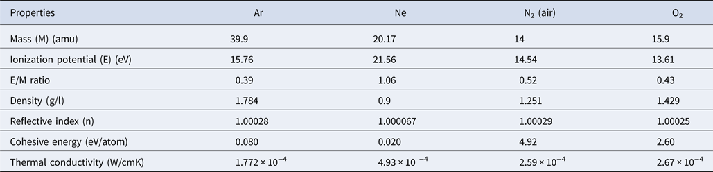
Some of the properties of gases are listed in Table 1 (Kittel, Reference Kittel2005). The effect of nature of ambient gas on plasma formation and confinement is mainly attributed to atomic mass, ionization potential, thermal conductivity, and cohesive energy of the background gas. The dependence of plume confinement on the atomic mass depends on the “mobility” of the background species and on its ability to convert the thermal energy into the internal degrees of freedom (Bulgakov and Bulgakova, Reference Bulgakov and Bulgakova1998). In case of the lighter background gas molecules, it is easier for the plume front to push them apart and to propagate further. The atomic mass also affects the strength of the backward shock waves. The heavier the background gas, more is the mass accumulated at the plume front, hence more are the confinement effects (Bulgakov and Bulgakova, Reference Bulgakov and Bulgakova1998). In case of O2 as an ambient environment, the smaller value of sputtering yield is observed because O2 is more reactive gas and results in more laser energy consumption in dissociation of molecules and chemical reactions of the reactive species. In case of Ar, the sputtering yield is maximum because of its less E/M value and less thermal conductivity. The cascade growth of electrons in laser plasma is more favorable for those gases having smaller E/M ratio (where E is ionization potential and M is mass). Therefore, Ar with the smaller E/M value, that is, 0.39 and smaller thermal conductivity, that is, 1.772 × 10⁻⁴ (W/cm K) gives maximum sputtering yield of Fe as compared with O2 which has higher values of E/M and thermal conductivity which are 0.43 and 2.67 × 10⁻⁴ (W/cm K), respectively.
Physical properties of background gases (Ar, O2, N2, or air and Ne), for example, mass (M), ionization potential (E), E/M ratio and thermal conductivity that are influencing laser-assisted plasma formation, ablation, and deposition yield of iron (Kittel, Reference Kittel2005)

SEM analysis
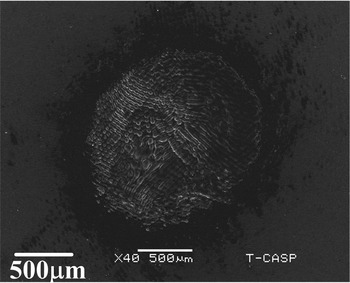
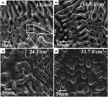
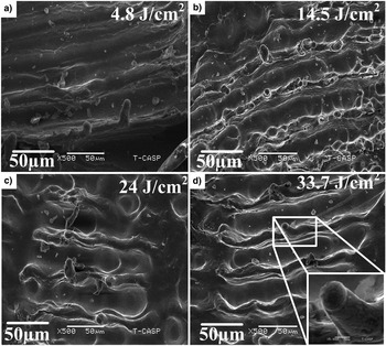
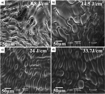
To correlate the sputtering yield with surface modifications of laser-ablated Fe, SEM analysis was performed. Figure 4 shows the overall ablated crater of Fe exposed to 100 pulses of Nd: YAG laser under 5 Torr Ar environment at a laser fluence of 33.7 J/cm2. The ablation spot area measured from SEM image for 100 pulses at 33.7 J/cm2 is 1.59 mm. In order to explore the effect of laser fluence and background gas pressure on surface modifications of laser-treated Fe, four fluences are selected and pressure of background gases is kept constant, that is, 5 Torr. SEM images of Figs 5–12 reveal modified surface of Fe after exposure to 100 Nd: YAG pulses at fluences of (a) 4.8 J/cm2, (b) 14.5 J/cm2, (c) 24 J/cm2 and(d) 33.7 J/cm2. SEM images of Fig. 5a–5d illustrate the effect of laser fluence on surface morphology of laser-irradiated Fe targets under 5 Torr Ar pressure. The central ablated area is mainly characterized by the formation of cavities with multiple ablative layers, channels, conical and dot-like structures. The number density of conical structures and channels increases initially as the fluence increases from 4.8 to 14.5 J/cm2. A further increase in fluence from 14.5 to 33.7 J/cm2 results in the complete evaporation of conical structures while channels and dot-like structures become diffusive.
SEM micrograph of laser-ablated crater on Fe surface at a fluence of 33.7 J/cm2 under Ar atmosphere at a pressure of 5 Torr.

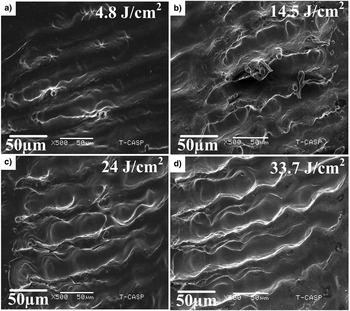
SEM micrographs revealing the surface morphology of central ablated area of Fe irradiated under 5 Torr Ar ambient at various laser fluences of (a) 4.8 J/cm2, (b) 14.5 J/cm2, (c) 24 J/cm2, and (d) 33.7 J/cm2.

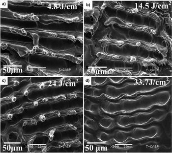
SEM micrographs revealing peripheral ablated area of Fe under 5 Torr Ar ambient at various laser fluences of (a) 4.8 J/cm2, (b) 14.5 J/cm2, (c) 24 J/cm2, and (d) 33.7 J/cm2.

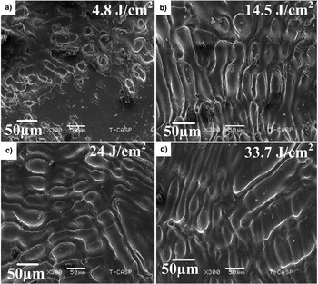
SEM micrographs exhibiting the central ablated area of Fe target under Ne environment irradiated at different laser fluences of (a) 4.8 J/cm2, (b) 14.5 J/cm2, (c) 24 J/cm2, and (d) 33.7 J/cm2.

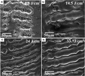
SEM micrographs revealing the comparison of variation of surface morphology at peripheral ablated area of Fe target under 5 Torr Ne environment at various laser fluences of (a) 4.8 J/cm2, (b) 14.5 J/cm2, (c) 24 J/cm2, and (d) 33.7 J/cm2.

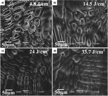
SEM micrographs showing central ablated area of laser-irradiated Fe at various laser fluences of (a) 4.8 J/cm2, (b) 14.5 J/cm2, (c) 24 J/cm2, and (d) 33.7 J/cm2 under 5 Torr O2 ambient.

SEM micrographs of peripheral ablated areas of laser-irradiated Fe target at various laser fluences of (a) 4.8 J/cm2, (b) 14.5 J/cm2, (c) 24 J/cm2, and (d) 33.7 J/cm2 under 5 Torr O2 environment.
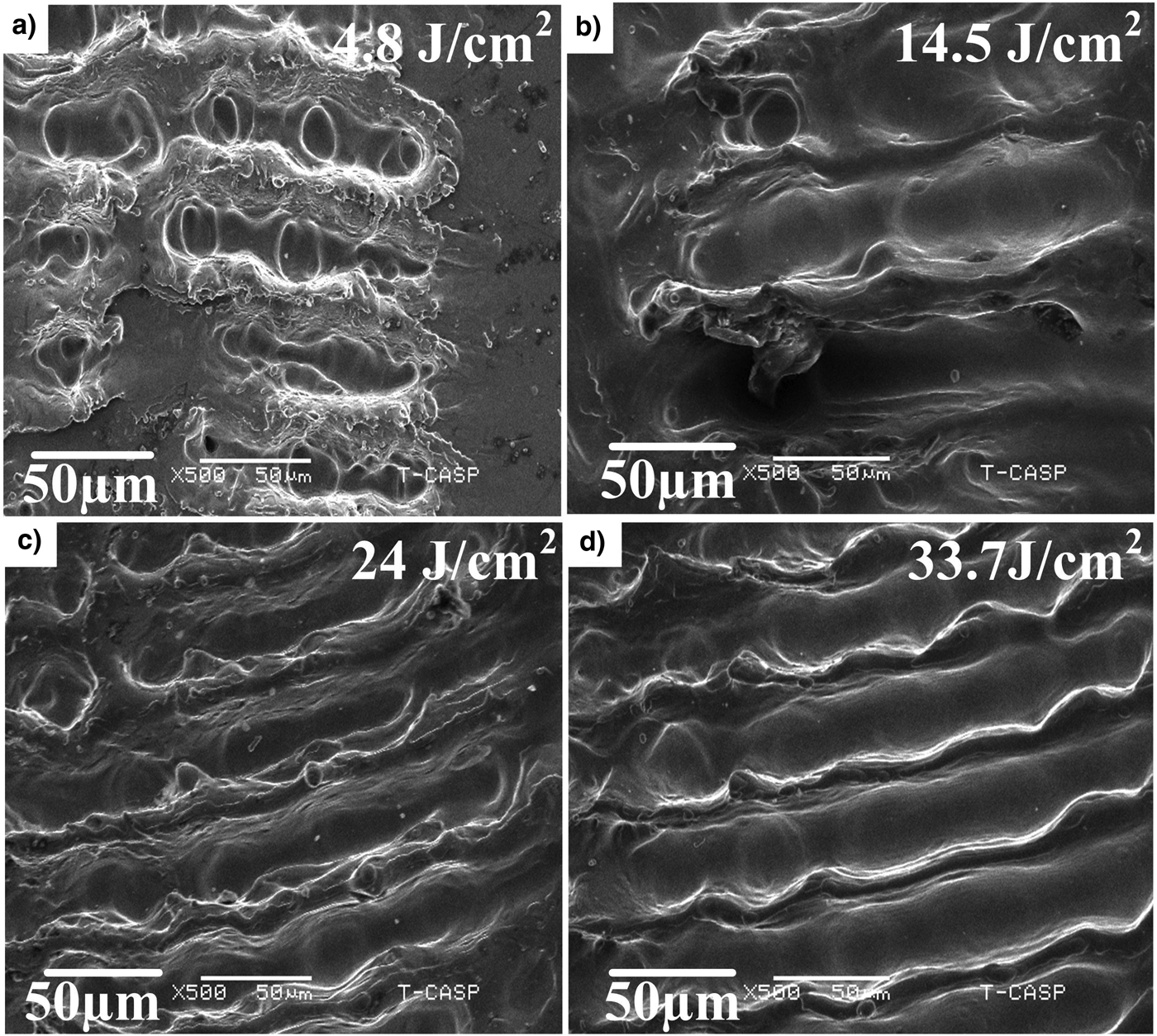
SEM micrographs revealing the variation of morphological features at center of the ablation crater under vacuum as a function of laser fluence, that is, (a) 4.8 J/cm2, (b) 14.5 J/cm2, (c) 24 J/cm2, and (d) 33.7 J/cm2.

SEM micrographs revealing the variation of morphological features at periphery of the ablation crater under vacuum as a function of laser fluences, that is, (a) 4.8 J/cm2, (b) 14.5 J/cm2, (c) 24 J/cm2, and (d) 33.7 J/cm2.

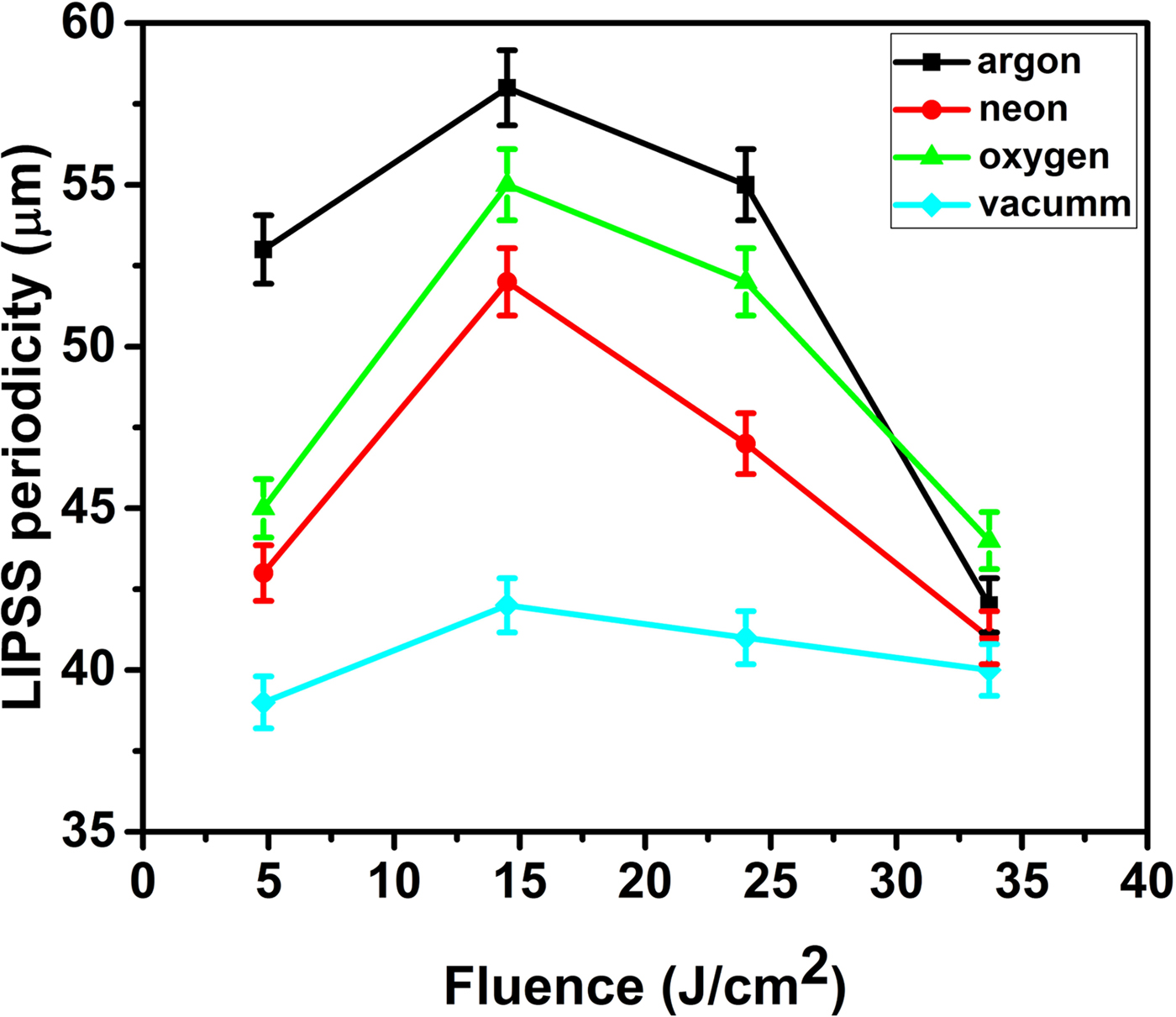
SEM micrographs in Fig. 6 reveal the peripheral ablated area of Fe under Ar ambient at fluences of (a) 4.8, (b) 14.5, (c) 24 and (d) 33.7 J/cm2. The dominant features at boundaries of ablation crater are laser-induced periodic surface structures (LIPSS) or well-organized micro scale ripples with spherical topped conical structures. The periodicity of these micro ripples first increases from 53 to 58 µm with increase in fluence and then decreases from 58 to 42 µm with further increase in fluence. The density of the conical structures grown over ripples initially increases with fluence up to 24 J/cm2 and further increase in fluence results in evaporation of these structures due to large amount of energy deposition.
The surface morphology of laser-ablated Fe target under Ne is displayed in the SEM micrographs of Figs 7 and 8. The SEM micrographs of Fig. 7a–7d show the central ablated areas of Fe target under 5 Torr Ne environment irradiated at different fluences of (a) 4.8, (b) 14.5, (c) 24 and (d) 33.7 J/cm2. Channels, cavities and dot-like structures are seen. Figure 7b shows the increase in the size and density of channels and dot-like structures with increasing fluence. Figure 7c shows the decrease in density of channels and increase of dot-like structures. The structures become diffusive and less distinct (Fig. 7d) at the highest fluence.
SEM images of Fig. 8a–8d illustrate the peripheral ablated area of Fe target under Ne environment. The dominant feature is incomplete ripple formation with bloated conical structures. Figure 8a shows the incomplete formation of LIPSS due to less energy deposition and the periodicity of these LIPSS is 43 µm. Figure 8b depicts that the density of conical structures over ripples as well as periodicity of these ripples also increases from 43 to 52 µm with increase in laser fluence. Figure 8c depicts that the conical structures become bloated and less organized with increase in fluence and the periodicity of ripples decreases from 52 to 47 µm. Figure 8d shows the significant decrease in the density of conical structures along with the decrease in periodicity of LIPSS from 47 to 41 µm at the maximum fluence.
SEM images of Fig. 9 illustrate the central ablated area of laser-irradiated Fe at fluences of (a) 4.8, (b) 14.5, (c) 24 and (d) 33.7 J/cm2 under 5 Torr O2 ambient. The dominant features are cavities with multiple ablative layers, molten channels and pores. At the lowest fluence of 4.8 J/cm2, the significantly high density of cavities is observed which decreases with increasing fluence up to 14.5 J/cm2. Further increase in fluence initiates the material melting and results in molten channels (Fig. 9c and 9d) from 24 to 33.7 J/cm2.
Figures 10a–10d reveal the SEM micrographs of peripheral ablated area of Fe exposed to 100 laser pulses at four fluences under O2 environment. Figure 10a depicts the formation of ripples with droplets over them with the periodicity of 45 µm. As the fluence increases up to 14.5 J/cm2, the periodicity of ripples increases from 45 to 55 µm and the growth of conical structures over the ripples start. In Fig. 10c with the increase of fluence to 24 J/cm2, the periodicity of LIPSS decreases from 55 to 52 µm and the conical structures over the LIPSS become more pronounced. Figure 10d shows that Fe surface treated at the maximum fluence of 33.7 J/cm2 reveals a decrease in periodicity up to 44 µm with complete disappearance of conical structures.
Figure 11a–11d reveals SEM micrographs of central ablated area of Fe target exposed to 100 laser pulses at four fluences under vacuum condition. Cavities with multiple ablative layers and channels are most prominent features. With the increase of fluence, these features become more diffusive due to more energy deposition and enhanced melting. SEM images of Fig. 12a–12d show the periphery of the ablation crater. Figure 12a represents the formation of diffusive ripples at a laser fluence of 4.8 J/cm2 due to less energy deposition. With the increase in fluence from 4.8 J/cm2 to a maximum value up to 33.7 J/cm2, the appearance of LIPSS becomes more distinct and well defined. The periodicity of ripples varies from 39 to 42 µm.
Discussion
The formation of cavities with multiple ablative layers can be attributed to laser-induced thermal desorption of underlaying gases or subsurface boiling, heating, melting and explosive boiling of target and also to the explosive relaxation of thermal stress in the superficial layer (Tokarev, Reference Tokarev2006). The size and densities of these cavities increase by increasing fluence up to certain value and then decreases due to refilling of the cavities by shock liquefied and melted material at higher fluences.
Unorganized and molten channel formation is attributed to the underneath cooling of molten material because of thermal conduction and density pressure gradients of liquid solid interface (Khalid et al., Reference Khalid, Bashir, Jalil, Akram, Hayat and Dawood2016). Forward peaked cones with wide bases and spherical tops are also observed. The growth of cones is the result of enhanced laser absorption at target surface due to voids, inhomogeneity, shielding effect, laser-induced defects, and grain boundaries momentum transfer from ions with an appearance of general convex-up protuberances (Khan et al., Reference Khan, Bashir, Hayat, Khaleeq Rahman and Haq2013). The formation of dot-like structures is more pronounced at higher fluences which is attributed to the melting of channels because of enhanced absorbance of laser light (Bashir et al., Reference Bashir, Rafique, Ajami and Husinsky2013).
LIPSS formation is explained on the basis of many theories such as generation of surface plasmon polaritons (Sipe et al., Reference Sipe, Young, Preston and Van Driel1983), Kelvin–Helmholtz instability (Ang et al., Reference Ang, Lau, Gilgenbach, Spindler, Lash and Kovaleski1998), and capillary waves (Shen et al., Reference Shen, Crouch, Carey, Younkin, Mazur, Sheehy and Friend2003). The formation of micro ripples in our study is attributed to Kelvin–Helmholtz instability (Ang et al., Reference Ang, Lau, Gilgenbach, Spindler, Lash and Kovaleski1998). According to this theory, the formation of micro ripples is caused by rapid heating and melting of surface layer and formation of laser-induced surface waves. The splashing, re-deposition, solidification and permanent engraving of the ablated material in the laser-induced surface layer results in micro ripples (Iqbal et al., Reference Iqbal, Bashir, Rafique, Dawood, Akram, Mahmood, Hayat, Ahmad, Hussain and Mahmood2015). The graph of Fig. 13 represents the effect of laser fluence on the periodicity of LIPSS under all ambient environments. The periodicity of LIPSS on Fe surface as a function of laser fluence ablated under 5 Torr Ar pressure is plotted in Fig. 13 (evaluated from Fig. 6a–6d). The periodicity initially increases with the fluence and achieves its maxima at a fluence of 14.5 J/cm2 and then decreases. The increase in periodicity with fluence is due to more energy deposition resulting in large-scale material deformation. At higher fluences, the periodicity decreases monotonically. This monotonic decrease in attributed to large-scale melting and re-solidification that results in merging of LIPSS (Bashir et al., Reference Bashir, Ali, Akram, Mahmood and Ahmad2012a).
The effect of laser fluence on the periodicity of laser-induced periodic surface structures (LIPSS) under ambient environments of Ar, Ne, O2, air, and vacuum.

Figures 5–12 depict the formation of various types of structures formed under different ambient environments at 5 Torr pressure. The nature of these features is almost similar in all environments. Table 2 shows the effect of environment on the nature of features grown on laser-irradiated Fe target. The features are most distinct in case of Ar than in Ne followed by O2 and vacuum. The difference between Ar and other atmospheres may stem from the difference in specific heat and the degree of freedom associated with the vibrational transitions and E/M ratio. The reasons of most distinct features in Ar are maximum energy deposition, favorable cascade growth, and minimum E/M as compared with all other ambient environments (Dawood et al., Reference Dawood, Bashir, Akram, Hayat, Ahmed, Iqbal and Kazmi2015). The lowest thermal conductivity of Ar as compared with other ambients is also responsible for the formation of distinct features due to minimum heat dissipation and maximum energy deposition (Bashir et al., Reference Bashir, Farid, Mahmood and Rafique2012b). The formation of distinct features is also attributed to plasma confinement effects near the target surface. These effects are more pronounced near target surface, hence resulting in less mass ablation in case of gases as compared with vacuum (Bashir et al., Reference Bashir, Khurshid, Akram, Ali, Ahmad and Yousaf2015). Table 2 demonstrates the effect of background environments on the growth and periodicity of laser-induced surface structures on Fe.
Effect of background environments on the growth and periodicity of laser-induced surface structures on iron

Optical microscopy
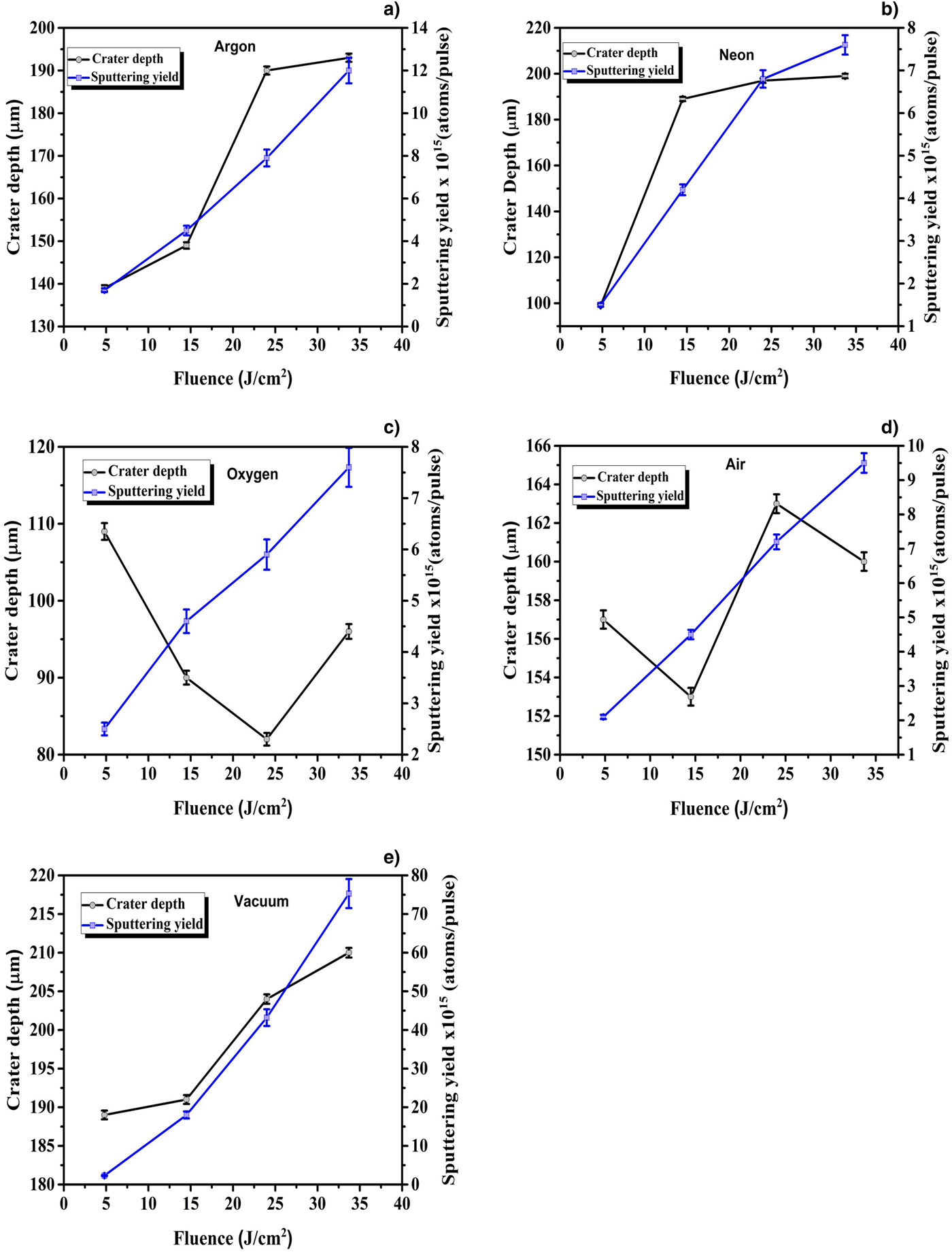
The measured crater depth and corresponding sputtering yields of Fe as a function of laser fluence under different ambient environments: Ar, Ne, O2, air, and vacuum are shown in Fig. 14a–14e. In our study, two different trends of ablation depth are observed: first one in case of inert environments, that is, vacuum, Ar, and Ne. This trend illustrates the monotonic increase and saturation of crater depth with increasing laser fluence. Second trend is observed in case of reactive environments, that is, O2 and air which shows a decrease in ablation depth with increasing fluence up to a certain limit and then the crater depth increases. The different behavior in case of reactive ambient can be explained on the basis of couple of mechanisms such as dissociation of gas molecules and chemical reactions occurring among reactive species (Bogaerts et al., Reference Bogaerts, Chen and Bleiner2006). The crater depth is in micrometer range for all fluences. The crater depth in case of Ar varies from 139 to193 µm; in the case of Ne, it varies from 99 to 199 µm; and in air, it ranges from 153 to 163 µm. In case of vacuum, depth lies between 189 and 210 µm, and in case of O2, it first decreases from 109 to 82 µm and then there is a slight increase in depth from 82 to 96 µm. The maximum crater depths are observed in case of vacuum, which is exactly in accordance with the sputtering yield results obtained from QCM. The crater depths observed are categorized in decreasing order as vacuum>Ar>Ne>air>O2. This trend is exactly comparable to one obtained trends from QCM analysis.
The effect of fluence on both crater depth and sputtering yields of laser-ablated Fe under background environment of (a) Ar, (b) Ne, (c) O2, (d) air, and (e) vacuum (10−3 Torr).

Four regimes of crater depth variation as a function of laser fluence are reported by Cristoforetti et al. (Reference Cristoforetti, Legnaioli, Palleschi, Tognoni and Benedetti2008): (a) first regime is the monotonic increase of depth with increase of fluence, (b) second one is saturation regime, (c) next one is gradual decrease in the crater depth and (d) forth one is again monotonic increase in crater depth. In our study, we are dealing with the first two regimes where crater depth increases and then saturates. In these two regimes, laser target coupling is very less effected by plasma-induced effects, hence more ablation rate is observed resulting in larger crater depths (Akram et al., Reference Akram, Bashir, Rafique, Hayat and Mahmood2017). It is also observed that the ablation threshold of metals is much less than gases. Due to high density, the plasma formation of target material starts exactly after the fluence value reaches the threshold fluence. At this point, the laser energy is wholly absorbed by target and plasma shielding effects are minimum. In addition to plasma generation, its hydrodynamic expansion plays an important role. At low irradiances and larger laser spot areas, plasma plume expands slowly, thus effectively absorbing and scattering the incoming laser beam and causes an increase in the ablation efficiency (Gojani et al., Reference Gojani, Yoh and Yoo2008).
The combination of laser fluence along with suitable environmental gases under certain pressures will provide optimum conditions for appropriate micro structuring and ablation of Fe target. For each material, this optimum condition will be different but its knowledge can provide better control over thin film deposition, ion implantation, and micro/nano structuring of materials.
XRD analysis
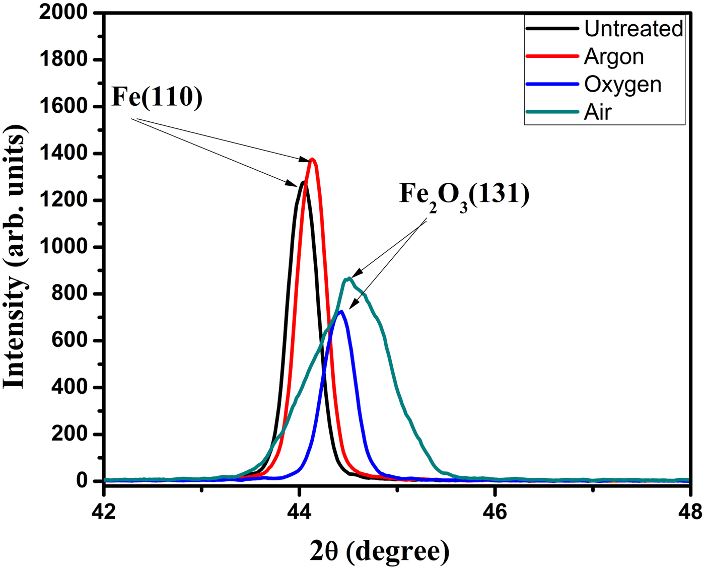
XRD analysis of unirradiated and laser-irradiated Fe samples at a fluence of 14.5 J/cm2 under 5 Torr pressure of Ar, O2, and air is revealed in Fig. 15. The diffraction peaks observed at 44.092° (for unirradiated sample) and 44.132° (for sample treated under Ar) corresponds to (110) phase which match with iron [Fe (pdf # 030654899)]. The diffraction peaks identified at 44.489° (for sample treated under O2) and 44.503° (for sample treated under air) correspond to (131) plane which matches with oxide phase of iron, that is, Fe3O4 (pdf # 000261136). This confirms the formation of oxide on the Fe surface after its treatment in reactive environments of O2 and air (Fig. 15).
The XRD pattern of unirradiated and laser-irradiated Fe targets at laser fluence of 14.5 J/cm2 under different environments of vacuum, Ar, Ne, O2, and air at a pressure of 5 Torr.

In addition to that there is a slight peak shifting and increase of peak intensity in all the laser-irradiated samples. The slight peak shifting is attributed to the laser-generated thermal and residual stresses on the surface of irradiated targets. The increase in peak intensity can be explained based on the surface defects generated by the laser pulse interaction with target surface. Laser irradiation causes melting of the sample, and on cooling the re-solidification, recrystallization processes take place and the gas atoms are diffused along the grain boundaries. Therefore, there is an increase in the concentration of the gas atoms in the sample which is indicated by the increase in the peak intensity (Jelani et al., Reference Jelani, Bashir, Akram, Yousaf, Afzal and Ahmad2014).
EDX analysis
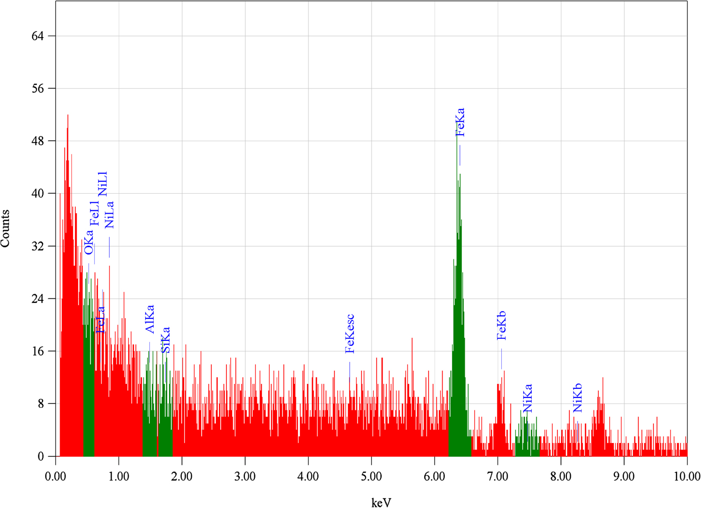
To analyze the composition of target and effect of environment on laser-ablated targets, EDX analysis was performed. For this purpose, EDX analysis of untreated and laser-treated targets at the laser fluence of 14.5 J/cm2 under 5 Torr gas pressure for Ar, O2 and air environments were analyzed and their weight percentages are listed in Table 3 and is shown in Fig. 16. The difference in the percentages of Al, Ni, and Si is attributed to the redeposition of atoms after sputtering and the presence of oxygen is attributed to the environmental effects. The presence of oxygen is attributed to the environmental effects or oxide formation of Fe after laser treatment in O2 and air.
The energy-dispersive X-ray graph revealing the percentage composition of untreated and laser-treated Fe target at laser fluence of 14.5 J/cm2 under 5 Torr pressure in O2.

Energy-dispersive X-ray spectroscopy (EDX) analysis of untreated and laser-treated iron targets at the laser fluence of 14.5 J/cm2 under 5 Torr gas pressure for Ar, O2, and air environments

Conclusions
The effect of laser irradiance, pressure and nature of ambient environment on sputtering yield, surface morphology and crater depth has been investigated. It is found that these parameters and their optimized combination play a decisive role for controlling ablation efficiency and surface modifications of Fe. It is revealed that the effect of fluence on sputtering yield is strongly dependent upon environmental conditions. In case of vacuum with increasing laser fluence, the sputtering yield of Fe increases monotonically. But this behavior is different in different environments. However, in case of Ar, O2 and air, the sputtering yield of Fe initially increases then decreases and finally saturates with increasing fluence from minimum to maximum. The effect of laser fluence is most pronounced in Ar followed by air and O2 and least in case of Ne. This trend of variation of sputtering yield with pressure is most significant in case of Ar, becomes moderate in case of O2 and air and least significant in case of Ne. The effect of nature of ambient on sputtering yield of laser-ablated Fe is observed in accordance with sequence as vacuum>Ar>Ne>air>O2. The significant effect of fluence and nature of environment on surface modification of laser-irradiated Fe is observed. The distinctness in the formation of the surface features is of the order Ar>Ne>O2> vacuum. These results show that the plasma characteristics and growth of surface structures depend on the laser energy absorption, which is influenced by the confining and shielding effects of plasma and nature of ambient gases. The effect of laser fluence on crater depth is found similar to the trends observed for sputtering yield under all ambient environments except for the case of O2. The structural analysis explored by XRD and EDX analyses confirm the oxide formation and percentage increase in oxygen content for Fe treated in O2 and air. Therefore, it is concluded that for any material, there is an optimum combination of fluence, environmental conditions and their pressures which are responsible for efficient enhancement of sputtering yield as well as micro/nano structuring of that material. These suitable parameters can make the materials more useful for different applications of thin film deposition, ion implantation as well as surface structuring.