1. Introduction
Robotic systems offer safer solutions for in-situ inspection and intervention [Reference Li, Yang, Yu, Liu, Kaynak and Gao1, Reference Almadhoun, Taha, Seneviratne, Dias and Cai2]. Many real-world environments – such as civil infrastructure, aeroengines, and pipework systems – require robots to access confined entry points (e.g. narrow gaps [Reference Wang, Li, Chang, Liu, Axinte and Dong3], aeroengine inspection holes [Reference Dong, Axinte, Palmer, Cobos, Raffles, Rabani and Kell4]) and operate within more open but cluttered spaces (e.g. isolated rooms [Reference Cheah, Groves, Martin, Peel, Watson, Marjanovic and Lennox5], aircraft wing and tank [Reference Marquette, Schultz, Jonnalagadda, Wong, Garbini and Devasia6]). The oil and gas sector demands access to ultra-long confined spaces [Reference Fang, Xiang, Ma, Liu, Wang and Liang7], whereas nuclear [Reference Chiou, Epsimos, Nikolaou, Pappas, Petousakis, Mühl and Stolkin8, Reference Kawatsuma, Mimura and Asama9] and medical [Reference Wang, Wang, Tang, Qiao, Liu and Hou10, Reference Gkegkes, Mamais and Iavazzo11] applications impose additional constraints such as the need for reliable retrieval and contamination management. Across domains, common challenges include limited accessibility, increased payload demands, and high deployment costs.
Continuum manipulators are increasingly used in the inspection and intervention of high-value infrastructure (e.g. aeroengines [Reference Wang, Dong, Ba, Mohammad, Axinte and Norton12, Reference Troncoso, Robles-Linares, Russo, Elbanna, Wild, Dong, Mohammad, Kell, Norton and Axinte13], aircraft wings [Reference Niu, Wang and Xu14]) and fragile environments (e.g. living bodies [Reference Mao, Yang, Tian, Shen, Wang, Zhang, Meng and Xie15], disaster-affected areas [Reference Yamauchi, Ambe, Nagano, Konyo, Bando, Ito, Arnold, Yamazaki, Itoyama, Okatani, Okuno and Tadokoro16]). These manipulators are valued for their robustness, structural integrity, relatively high payload capacity, and safe retrieval in failure scenarios. Typically defined as continuously bending structures [Reference Walker, Choset and Chirikjian17, Reference Burgner-Kahrs, Rucker and Choset18] actuated from the base [Reference Russo, Sadati, Dong, Mohammad, Walker, Bergeles, Xu and Axinte19], their development initially focused on miniaturised medical applications [Reference Simaan, Taylor and Flint20, Reference Webster21]. With the slender configuration, they now enable broader use in manufacturing [Reference Kumar22], aerospace [Reference Ma, Monk and Cheneler23], search and rescue [Reference McFarland, Dhawan, Kumari, Council, Coad and Hanson24], and nuclear industries [Reference Li, Yu, Dong, Pan, Wu, Cao, Pei, Huang and Yi25]. As environments grow more complex, requiring higher depth-to-diameter ratios and tighter turns, conventional continuum manipulators face a bottleneck: increasing the number of controllable segments demands more actuators, which enlarges the actuation pack and raises costs and deployment difficulty. Strategies such as underactuation [Reference Bishop, Russo, Dong and Axinte26], special tendon routing [Reference Starke, Amanov, Chikhaoui and Burgner-Kahrs27], and embedded microunits [Reference Kang, Guglielmino, Zullo, Branson, Godage and Caldwell28] have been explored, but often at the cost of a thicker body.
An alternative approach decouples the number of actuators from the number of bending sections by adopting an endoscope-like insertion strategy [Reference Long, Cinquin, Troccaz, Voros, Berkelman, Descotes, Letoublon and Rambeaud29], where the tip remains steerable although the body passively follows. Active structures have been introduced near the tips of endoscopes and continuum manipulators to enhance this type of design. Locomoting mechanisms such as rolling [Reference Kim, Choi, Keum and Chun30] and worming [Reference Takamatsu, Endo, Fukushima, Yasue, Shinmura, Ikematsu and Takemura31] allow the robot actively moving in the environment, but integration remains a challenge due to the limited access port. In contrast, the concept of creating a stabilising platform through inflation – originally developed for medical applications [Reference Yamamoto, Sekine, Sato, Higashizawa, Miyata, Iino, Ido and Sugano32] – has been extended to industrial tasks such as pipework inspection [Reference Atalla, Trauzettel, van Gelder, Breedveld, Wiertlewski and Sakes33], exploration [Reference Yarbasi and Samur34], and aeroengine thermal barrier coating repair [Reference Chang, Dai, Wang, Axinte and Dong35]. However, this strategy relies heavily on the manipulator being laterally supported along its entire insertion path to prevent buckling and ensure anchoring stability. Its functionality becomes significantly limited in environments with alternating narrow and surface-supported regions.
Insertion-induced buckling of slender and continuum manipulators has long been studied within the framework of classical beam theory and elastica formulations, where self-weight buckling and large deflection behaviour are well established through Greenhill-type analysis and Euler–Bernoulli theory [Reference Greenhill36]. Building on this foundation, more recent studies have focused on modelling insertion mechanics of, catheter-based [Reference Baek, Cheon, You and Kwon37], and continuum manipulators [Reference Burgner-Kahrs, Rucker and Choset18] under frictional contact and confinement, often employing Cosserat rod [Reference Boyer, Lebastard, Candelier, Renda and Alamir38, Reference Miller, Su, Pabon, Wicks, Bertoldi and Reis39] or elastica-based formulations that require solving coupled Ordinary Differential Equations (ODEs), Partial Differential Equations (PDEs), or Nonlinear Programmes (NLPs) to capture large deformation, distributed loading, and contact interactions. These methods can provide detailed predictions of deformation and contact behaviour, but they typically require a numerical solver, a prescribed contact topology, and problem-specific boundary conditions. They are therefore less convenient for rapid path screening during field deployment, particularly when the insertion route contains several distinct contact modes. In the present application, resistance may arise sequentially from distributed ground contact, the end-effector, isolated wall contact, and wrapping around obstacles. This motivates a deployment-oriented assessment framework that combines these resistance contributions within a closed-form calculation and returns a conservative estimate of the insertion force and buckling margin. The framework is intended for rapid feasibility assessment rather than high-fidelity shape prediction.
This paper proposes a low-cost extra-long continuum manipulator with a modular design to overcome the challenges described above:
-
• A modular continuum-manipulator architecture is developed for hybrid deployment paths comprising a confined entrance, extended surface-supported or loosely constrained regions, and a final elevated inspection task. Unlike systems that depend on continuous lateral confinement, the proposed manipulator can advance across regions without continuous body support and remain safely retrievable.
-
• A self-recoverable passive body is integrated with an independently actuated dual-balloon stabilisation unit. This configuration separates long-range insertion from distal stabilisation, allowing the manipulator to transition from passive path following to a supported lift-up configuration at the target location.
-
• A solver-free insertion-stability assessment framework is formulated by combining distributed ground resistance, tip resistance, isolated wall-contact resistance, and wrapping resistance. The framework provides a conservative buckling-margin estimate for rapid structural design and deployment-path screening.
Deployment was successfully demonstrated in a decommissioning nuclear hot cell at Nuclear Restoration Services (NRS) Dounreay, UK. A mock-up trial reflects the entire deployment process. Such inspection challenges frequently arise in large industrial facilities and infrastructure assets, including nuclear decommissioning plants, where access through confined entry points is often required.
2. Targeted environments and system design
2.1. General environment and system concept
Industrial inspection frequently involves hybrid environments combining narrowly confined entry regions with loosely constrained internal paths. Such hybrid geometries are common in nuclear facilities, pipework systems, and large industrial structures. Access is typically provided through narrow gaps, whereas inspection targets are located across open floor regions, vertical surfaces, or elevated components.
For clarity, the environments considered in this study are classified according to the degree and form of external support. A fully constrained environment continuously supports the manipulator laterally, as in a pipe or narrow channel. A loosely constrained environment provides only partial or intermittent support and may contain several distinct contact modes. These include surface-supported contact, in which the manipulator rests on a horizontal or inclined surface and experiences distributed friction; wall contact, in which a discrete obstacle produces a local reaction and frictional resistance; and wrapping contact, in which the manipulator remains in extended contact with a curved obstacle over a finite wrapping angle. An unconstrained environment refers to a span with no meaningful lateral or surface support. The present stability framework primarily addresses loosely constrained paths containing one or more of the above contact modes.
These conditions create a deployment challenge; a slender device must traverse partially supported paths, transition between different contact modes, and generate elevation without continuous lateral confinement. Conventional insertion strategies, in which only the tip is actively steered and the body passively follows, perform well in fully constrained channels but may become unstable when extended across surface-supported regions without continuous lateral confinement.
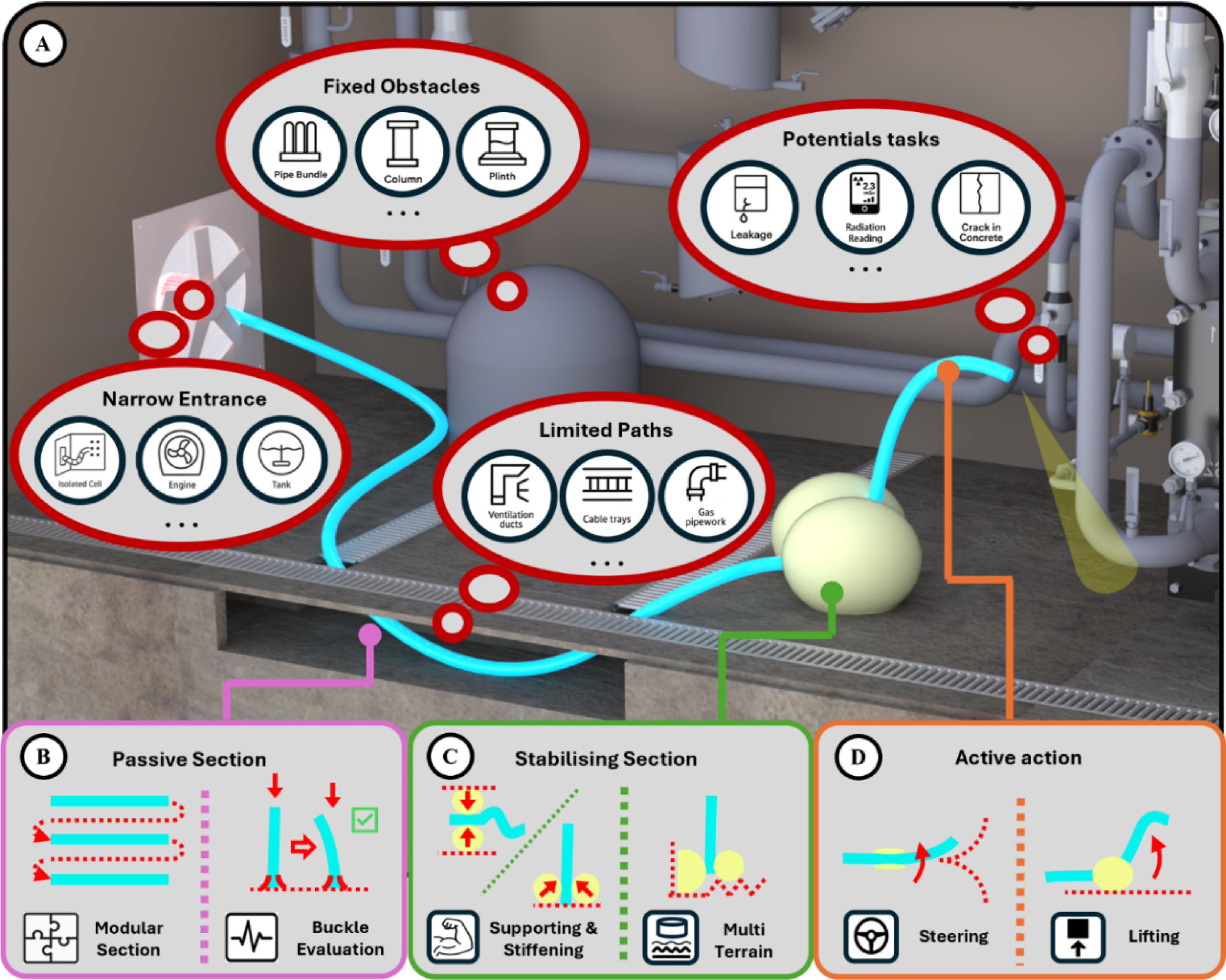
To address this class of environments, an extra-long continuum manipulator is proposed (Figure 1). The system comprises three functional sections: an active steering section, a dual-balloon stabilising section incorporating two independently actuated balloon membranes, and a passive compliant body. The two balloon membranes are mounted on opposite sides of a revolute joint and are connected to separate pneumatic supply lines, allowing their inflation pressures to be controlled independently. The slender structure enables navigation through restricted access points, while the stabilising section supports controlled lift-up and sustained positioning in semi-confined spaces. The passive body tolerates environmental contact and recovers from bending, supporting long-reach deployment under loosely constrained environment with practical loading conditions.
Schematic of the extra-long continuum manipulator. a: General use case, b: Function of passive section, c: Function of stabilising section, and d: Function of the active section.

Figure 1. Long description
Panel A: The diagram illustrates a general use case of the robotic system in a cluttered environment with fixed obstacles like pipe bundles, columns, and plinths. It also shows potential tasks such as detecting leakage, radiation reading, and identifying cracks in concrete. The environment includes narrow entrances leading to isolated cells, engines, and tanks, as well as limited paths with ventilation ducts, cable trays, and gas pipework. Panel B: The passive section of the robotic system is depicted with modular sections and buckle evaluation. Panel C: The stabilizing section is shown with supporting and stiffening mechanisms, and the ability to navigate multi-terrain. Panel D: The active section includes steering and lifting functionalities.
2.2. Prototype implementation
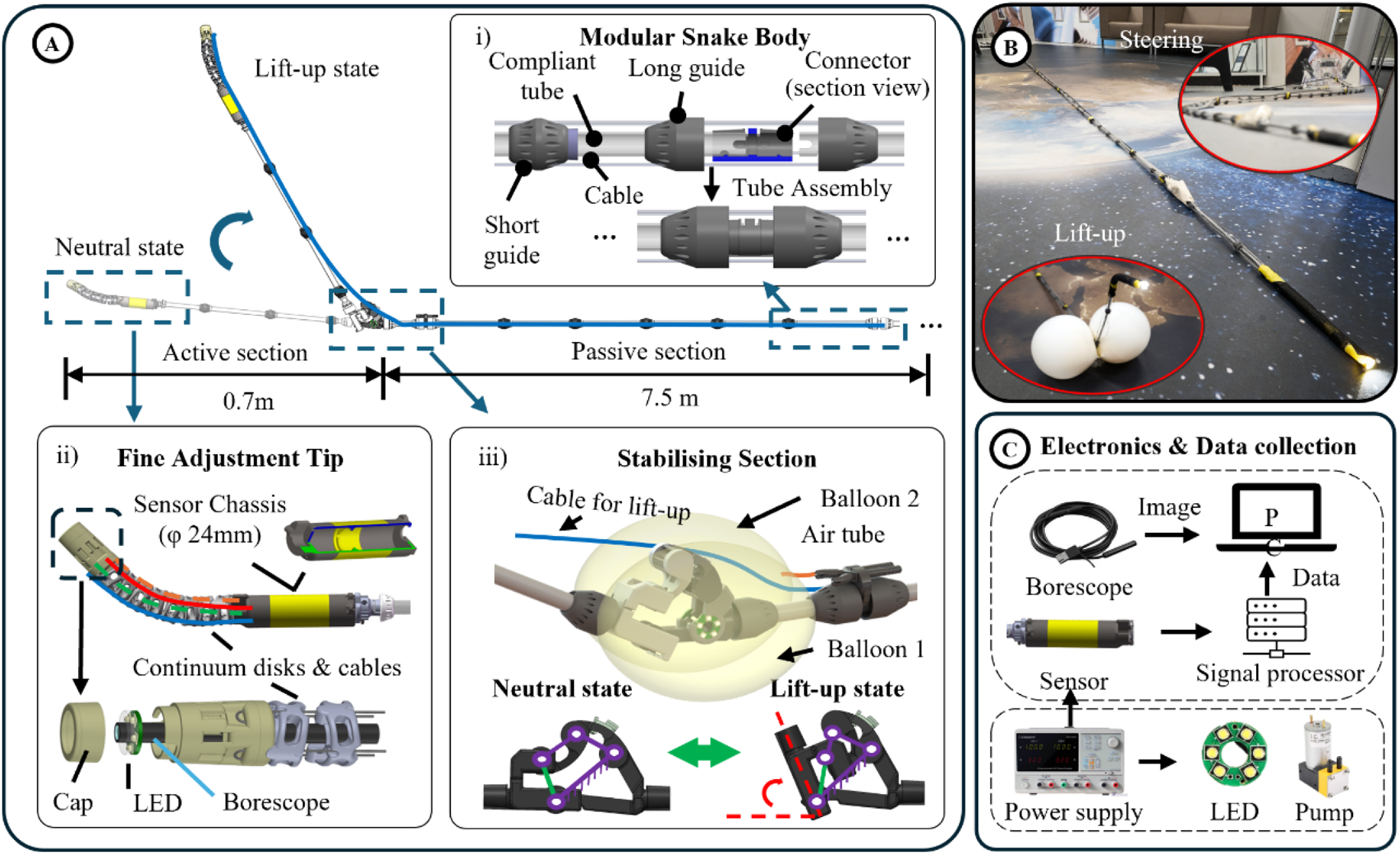
Aligning with a low-cost mindset, we prototyped an 8.2 m long manipulator with 3D-printed parts and off-the-shelf components, as shown in Figure 2. The central working channel and section compliance are secured using Polyethylene Terephthalate Glycol-modified (PETG) tubing (outer diameter 12 mm, inner diameter 10 mm). Tubing with maximum length of 1 m is connected, similar to a fishing rod, by rigid 3D-printed connectors for rapid assembly. Guides are fixed to the tubing for cable guidance, while long guides (Figure 2a) appear on both sides of the tubing connector, acting as push-in lockers for the tubing connection. The design also enables the manipulator to be folded (semi-disassembled) into a 1 m bundle, with the electronics and cables readily assembled for convenient delivery and deployment.
Prototype of the extra-long continuum manipulator. a: Design of the prototype, b: Prototype figure, and c: Integrated electronics.

The prototype has been built for the inspection of a nuclear decommissioning cell. Borescopes were integrated at the end of the active section and behind the stabilising section, respectively, for visual inspection of the environment and for monitoring the condition of the two balloons in the stabilising section. High-power Light-Emitting Diodes (LEDs) were integrated at the tip and adjacent to the stabilising section to provide sufficient illumination in the dark environment. A 70 g customised online radiation sensor is mounted in the general sensor chassis for observing radiation readiness. The 10 mm hollow working channel from the tubing secures the cable connections of the electronics, which are all linked to the actuation pack of the manipulator and connected to the corresponding devices.
The active section consists of a fine adjustment tip and a steerable head. Being covered by a cable sleeve, the fine adjustment tip (outer diameter 24 mm), with a 3D-printed (Tough 2000, Formlabs) pivot joint design [Reference Dong, Axinte, Palmer, Cobos, Raffles, Rabani and Kell4], enables 2-Degrees of Freedom (DoF) bending motion with 110° bending angle, allowing the front borescope to point in the desired direction with a small bending radius. The steerable head, made of PETG tubing, provides sufficient stiffness to enable navigation by engaging with the environment.
The stabilising section incorporates a revolute joint that releases the reaction moment generated by the deformed passive body during the lift-up motion. A four-bar linkage minimises the restoring moment of the joint while maintaining a mechanically constrained configuration during insertion. Two balloon membranes are mounted on opposite sides of the revolute joint and connected to separate pneumatic supply lines, enabling independent inflation and deflation.
When both balloons are deflated, their membranes remain tensioned around the joint and work with the mechanical stops to restrict unintended rotation during navigation. Once the stabilising section reaches the target location, the two balloons are inflated through their respective pneumatic lines to establish support against the surrounding structure. Their pressures can be adjusted independently to accommodate asymmetric contact conditions and to stabilise the revolute joint during the subsequent lift-up motion.
3. Insertion stability assessment framework
Long-reach deployment requires estimating whether the manipulator can reach the target location without insertion-induced buckling. This section develops an assessment method to support:
-
1. Selection of structural stiffness during design.
-
2. Evaluation of allowable navigation depth during deployment planning.
The objective is to provide a conservative stability bound for practical decision-making.
3.1. Navigation distance on under surface-supported contact
This section considers a surface-supported contact condition within a loosely constrained environment. The manipulator rests on a supporting surface and is advanced approximately along its longitudinal axis without continuous lateral confinement. Insertion-induced buckling is assumed to initiate near the proximal boundary of the unsupported or weakly supported span. The principal axial resistances are the distributed friction generated by the body weight
 $F_{\mathrm{s}}$
and the frictional resistance at the end-effector
 $F_{\mathrm{tip}}$
. Defining the beam material density
 $\rho$
and the cross-sectional area A,
 $F_{\mathrm{s}}$
and
 $F_{\mathrm{tip}}$
can be respectively described through the Coulomb coefficient
 $\mu _{\text{body}}$
and
 $\mu _{\mathrm{tip}}$
is expressed as:
 \begin{align}\left\{\begin{array}{rl} F_{\mathrm{s}}\left(x\right) &={\mu} _{\text{body}}\rho Ag\left(l_{\max }-x\right)\\ F_{\mathrm{tip}}&={\mu} _{\mathrm{tip}}m_{\mathrm{tip}}g \end{array}\right.\end{align}
where
 $m_{\mathrm{tip}}$
is the mass of the integrated end-effector;
 $l_{\max }$
is the maximum length of the beam before buckling;
 $g$
is the gravitational acceleration; and
 $x$
is the position along the beam.
The situation can be simplified as a Euler–Bernoulli cantilever beam, and the equilibrium (critical state) for buckling can be expressed as:
 \begin{equation}EI\frac{d^{4}y(x)}{dx^{4}}+(F_{\mathrm{tip}}+F_{s}(x))\frac{d^{2}y(x)}{dx^{2}}=0\end{equation}
where
 $E$
is the Young’s modulus of the beam;
 $I$
is the second moment of inertia of the beam; and
 $y$
is the beam deflection.
By a change of variable
 $z=(l_{\max }-x)+F_{\mathrm{tip}}/(\mu _{\text{body}}\rho Ag)$
, the equation reduces to the classical Greenhill self-buckling challenge [Reference Timoshenko and Gere40] with an unloaded effective length
 $l_{0}=l_{\max }+F_{\mathrm{tip}}/(\mu _{\text{body}}\rho Ag)$
, leading to a maximum beam length:
 \begin{equation}l_{\max }=l_{0}-\frac{F_{\mathrm{tip}}}{\mu _{\text{body}}\rho Ag}\end{equation}
where
 $l_{0}$
, based on the Greenhill challenge, can be expressed as:
 \begin{equation}l_{0}\approx \left(\frac{CEI}{\mu _{\text{body}}\rho Ag}\def\lumina\hspace{0pt}\right)^{\frac{1}{3}}\end{equation}
where the numerical coefficient
 $C=7.8373$
corresponds to the first dimensionless eigenvalue of the classical Greenhill self-weight buckling problem. It encapsulates the effect of distributed axial compression and boundary conditions on the onset of instability, rather than representing a material parameter.
Hence, leading to a conclusion:
 \begin{equation}l_{\max }\approx \left(\frac{CEI}{\mu _{\text{body}}\rho Ag}\def\lumina\hspace{0pt}\right)^{\frac{1}{3}}-\frac{\mu _{\mathrm{tip}}m_{\mathrm{tip}}}{\mu _{\text{body}}\rho A}\end{equation}
As a result, Eq. (5) therefore provides a closed-form upper bound for the maximum insertion length under surface-supported contact. It offers a direct design criterion linking material stiffness, cross-sectional geometry, distributed surface friction, and tip resistance to the onset of insertion-induced buckling.
3.2. Buckling assessment along a hybrid contact path
A loosely constrained deployment path may contain several sequential contact modes. For the present assessment, the corresponding insertion resistance
 $F_{\mathrm{sum}}$
is decomposed into four contributions:
-
1. Ground resistance
 $F_{\mathrm{s}}$
: distributed friction arising from surface-supported contact along the manipulator body, derived in Eq. (1);
-
2. Tip resistance
$F_{\mathrm{tip}}$
: frictional resistance acting at the end-effector, derived in Eq. (1); -
3. Wall resistance
$F_{\text{wall}}$
: local friction generated when the manipulator is deflected against a discrete wall or obstacle. -
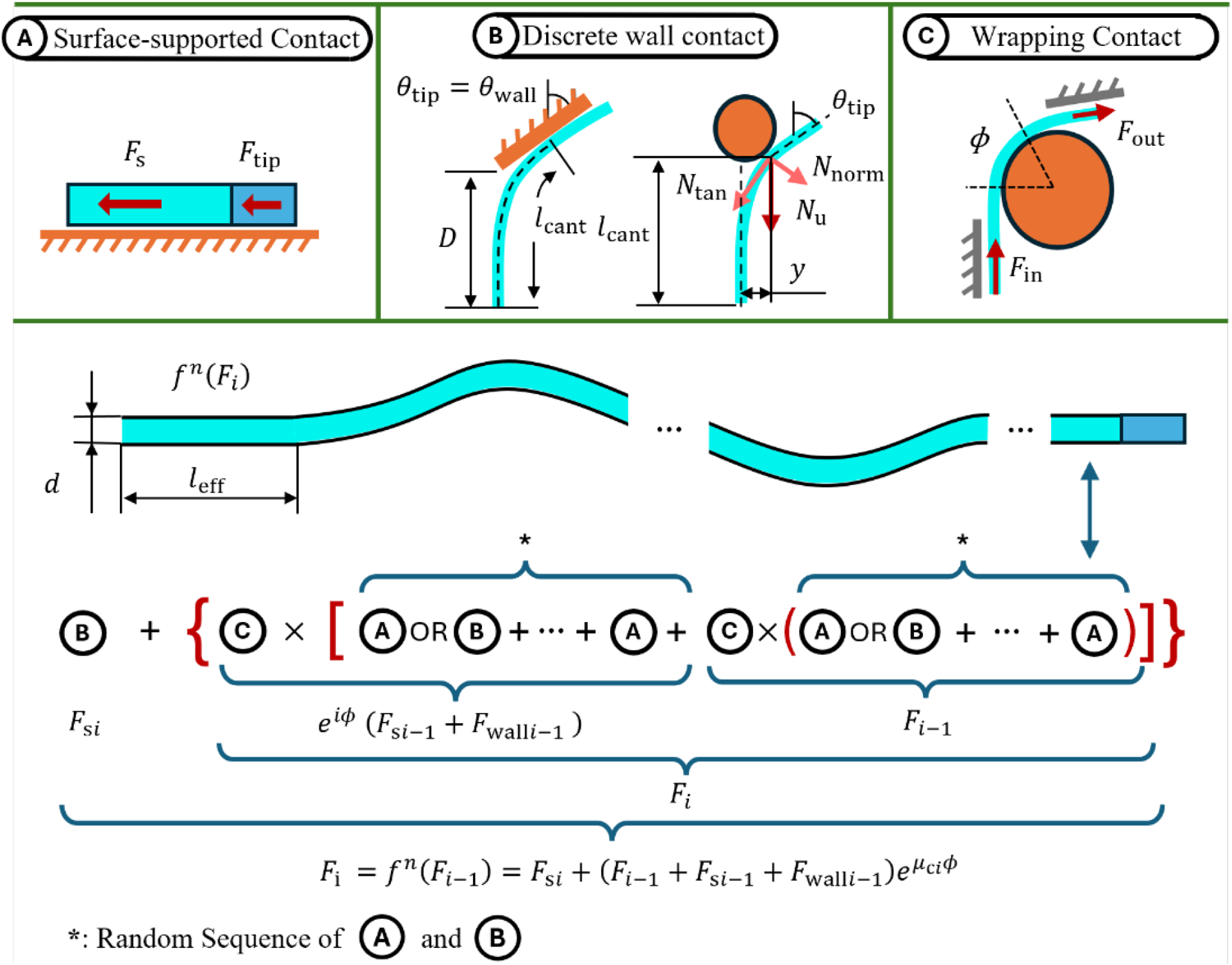
4. Wrapping resistance: force-transmission loss generated when the manipulator remains in continuous contact with a curved obstacle, such as a plinth or column, over a known wrapping angle
$\phi$
;


where the last condition complies with the capstan friction formula [Reference Bickford41]. Defining
 $F_{\mathrm{out}}$
as the force leaving the segment on the distal side, and
 $F_{\mathrm{in}}$
as the force entering the wrapping segment from the proximal side, the force approximates an exponential relationship under the Coulomb friction coefficient
 $\mu _{c}$
, expressed as:
 \begin{equation}F_{\mathrm{out}}=F_{\mathrm{in}}e^{-{\mu _{\mathrm{c}}}\phi }\end{equation}
Contact modes considered in the insertion-stability assessment. a: Surface-supported contact with distributed ground and tip resistance, b: Discrete wall contact, and c: Wrapping contact around a curved obstacle.

The hybrid path is divided into segments according to the locations of the wrapping contacts. The resistance generated in each distal segment is propagated towards the proximal actuation end using the inverse capstan relation. By segmenting the environment through wrapping, the transferred resistance
 $F_{i}=f(F_{i-1})$
after the number
 $i$
wrapping resistance (count from the head of the manipulator) can be expressed as:
 \begin{equation}F_{i}=F_{\mathrm{s}i}+{\left(F_{i-1}+F_{\mathrm{s}i-1}+F_{\text{wall}i-1}\right)}{e}^{{\mu _{\mathrm{c}i}}\phi }\end{equation}
Accordingly, each wrapping segment increases the proximal force required to overcome the resistance located beyond that segment. The positive exponent used in Eq. (7) therefore represents inverse force propagation for calculating the required actuation force; it does not represent physical force amplification across the contact.
Defining the effective beam length
 $l_{\mathrm{eff}}$
and the column effective length coefficient
 $K=2$
for the case of a cantilever beam, the buckling discriminant can be expressed as:
 \begin{equation}F_{\mathrm{sum}}=f^{n}\!{\left(F_{i}\right)}\geq F_{cr}=\frac{\pi ^{2}EI}{\left(Kl_{\mathrm{eff}}\right)^{2}}\end{equation}
where
 $i=0,1,\ldots ,n-1$
is the number of the wrapping resistance counting from the head of the manipulator.
With Coulomb friction coefficient
 $\mu _{\text{wall}}$
for the wall, the wall resistance can be expressed as:
 \begin{equation}F_{\text{wall}}=\mu _{\text{wall}}N_{\text{norm}}+N_{\text{axis}}\end{equation}
where
 $N_{\text{norm}}$
is the support reaction from the beam deformed by the wall (Figure 3).
To account for large deformations, we employed the elastica formulation and used a fifth-order Taylor expansion [Reference Bisshopp and Drucker42] as an approximate solution. The force along the normal direction of the unbent body
 $N_{\mathrm{u}}$
(Figure 3) can be expressed as:
 \begin{equation}N_{\mathrm{u}}\approx N_{0}\left(1+\frac{9y^{2}}{35{l_{\text{cant}}}^{2}}+\frac{2358y^{4}}{13475{l_{\text{cant}}}^{4}}\right)\end{equation}
where
 $l_{\text{cant}}$
is the effective length of the cantilever beam, and
 $N_{0}$
is the linear term corresponding to the Euler–Bernoulli prediction [Reference Timoshenko and Gere40], expressed as:
 \begin{equation}N_{0}=\frac{3EI}{{l_{\text{cant}}}^{3}}y\end{equation}
For large deformation, the tip angle
 $\theta _{\mathrm{tip}}$
is significant. Therefore, the correlation between
 $N_{\mathrm{u}}$
and
 $N_{\text{norm}}$
can be expressed as:
 \begin{equation}\begin{cases} N_{\text{norm}}=N_{\mathrm{u}}\cos \theta _{\mathrm{tip}}\\ N_{\text{axis}}=N_{\mathrm{u}}\sin \theta _{\mathrm{tip}} \end{cases}\end{equation}
where
 $N_{\text{axis}}$
is the force along the tangent direction of
 $N_{\text{norm}}$
.
The tip angle
 $\theta _{\mathrm{tip}}$
can be obtained in the same manner by a fifth-order Taylor expansion, expressed as:
 \begin{equation}\theta _{\mathrm{tip}}\approx \frac{{N_{\mathrm{u}}}{l_{\text{cant}}}^{2}}{2EI}+\frac{{N_{\mathrm{u}}}^{3}{l_{\text{cant}}}^{6}}{24E^{3}I^{3}}+\frac{3{N_{\mathrm{u}}}^{5}{l_{\text{cant}}}^{10}}{40E^{5}I^{5}}\end{equation}
substituting the
 $N_{\mathrm{u}}$
into
 $\theta _{\mathrm{tip}}$
, the result can be expressed as:
 \begin{equation}\theta _{\mathrm{tip}}\approx \frac{3y}{2l_{\text{cant}}}\left(1+\frac{75y^{2}}{112{l_{\text{cant}}}^{2}}+\frac{6379767y^{4}}{689920{l_{\text{cant}}}^{4}}\right)\end{equation}
For each wall-contact configuration,
 $l_{\text{cant}}$
and
 $y$
are obtained directly from the prescribed obstacle geometry, and
 $\theta _{\mathrm{tip}}$
is evaluated using the fifth-order beam approximation. These quantities are then used to calculate
 $N_{u}$
, after which
 $N_{\text{norm}}$
and
 $N_{\text{axis}}$
are obtained by resolving the force relative to the wall-contact direction. The calibrated wall-contact coefficient is finally applied to calculate the corresponding frictional resistance.
In summary, Eq. (5) estimates the maximum insertion length for the baseline surface-supported contact condition. A loosely constrained hybrid path may additionally contain discrete wall-contact and wrapping-contact segments. The resistance associated with each segment is evaluated according to its contact mode and propagated towards the actuation end using Eq. (7). The resulting proximal insertion-force demand is then compared with the critical buckling load through the discriminant as in Eq. (8).
4. Framework validation under controlled testbeds
4.1. Validation of the critical insertion length under surface-supported contact
This experiment validates the baseline surface-supported contact model developed in Section 3.1. The test reproduces distributed friction along the rod while excluding discrete wall-contact and wrapping-contact effects. The resulting critical insertion length provides a baseline criterion for selecting the manipulator stiffness and estimating the allowable insertion distance before deployment.
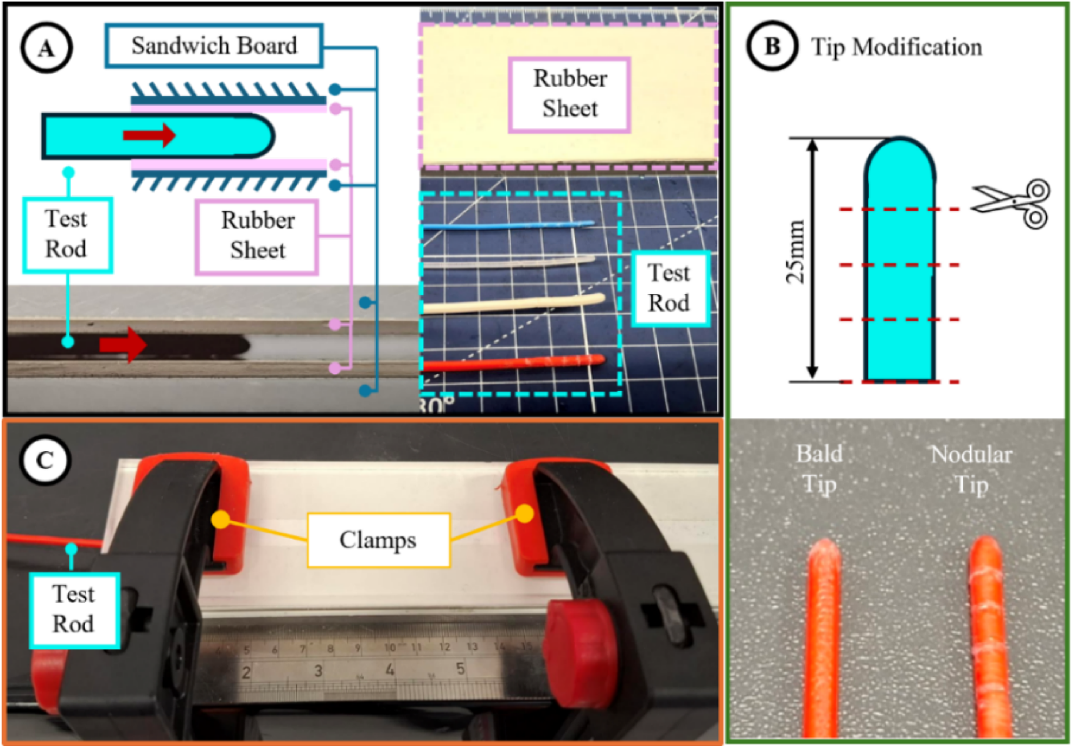
The critical buckling length can guide the design of the manipulator, ensuring that the effective insertion length eventually reaches the target depth after navigation. A scaled-down dummy test has been conducted to prove the effectiveness of the modelling. The validation focuses on straight horizontal insertion, which provides a baseline for the initial design of the manipulator prototype. As shown in Figure 4, to maximise the distributed friction along the length, we sandwiched the rods between rubber sheets. The rubber sheets were fixed on rigid boards and pressed by two clamps, with the height controlled by spacers placed at the corners and edges of the boards. 3D printing filaments were chosen as the testing rods, and the straightness was mechanically improved at room temperature. To distinguish the friction between the manipulator tip and the manipulator body, tip modification was carried out by applying ring carvings at the tip of the rods to vary the friction coefficient.
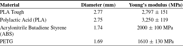
List of the test rod.

Table I. Long description
A table with four rows and three columns comparing the diameter and Young’s modulus of different materials. The columns are labeled Material, Diameter (mm), and Young’s modulus (MPa). The rows list the following data: Row 1: Material, Polylactic Acid (PLA) Tough; Diameter, 2.77; Young’s modulus, 2,797 151. Row 2: Material, Polylactic Acid (PLA); Diameter, 2.75; Young’s modulus, 3,250 119. Row 3: Material, Acrylonitrile Butadiene Styrene (ABS); Diameter, 1.74; Young’s modulus, 2000 100 MPa. Row 4: Material, PETG; Diameter, 1.69; Young’s modulus, 1610 130 MPa.
Preparation for the critical buckling length test. a: Setup configuration, component, and test rods to be inserted, b: Tip modification for friction coefficient variation, and c: Test setup.

Four different rods were selected for the validation test. The diameters are measured from a caliper, and the Young’s modulus was obtained from the product data sheet. The specification is listed in Table I.
By introducing the body line friction density
 ${F}_{\mathrm{s}}^{\mathrm{'}}$
and tip friction density
 ${F}_{\mathrm{tip}}^{\mathrm{'}}$
,
 $l_{\max }$
in Eq. (5) can be rewritten as:
 \begin{equation}l_{\max }\approx \left(7.8373\frac{EI_{\mathrm{rod}}}{{F}_{\mathrm{s}}^{\mathrm{'}}}\def\lumina\hspace{0pt}\right)^{\frac{1}{3}}-\frac{{F}_{\mathrm{tip}}^{\mathrm{'}}}{{F}_{\mathrm{s}}^{\mathrm{'}}}\end{equation}
where
 $I_{\mathrm{rod}}=\frac{\pi }{64}{D_{\mathrm{rod}}}^{4}$
is the cross-sectional moment of the inertia, and
 $D_{\mathrm{rod}}$
is the diameter of the rod.
Before the critical-buckling-length tests, the friction parameters of each rod material were calibrated once using the same rubber-sheet configuration. During calibration, the rod was inserted through the complete length of the rubber sheets and allowed to protrude from the opposite end. This arrangement ensured that, when the rod was pulled using the dynamometer, the full length of the rubber-sheet contact region corresponded to the line-friction calculation length.
The pulling force was first measured using the reference rod tip to identify the distributed body friction over the known contact length. The resulting body line-friction density was calculated by dividing the measured distributed resistance by the rubber-sheet contact length. A second measurement was then conducted using the modified nodular tip. After subtracting the distributed body-friction contribution, the remaining force was attributed to the tip resistance. The resulting calibrated
 ${F}_{\mathrm{s}}^{\mathrm{'}}$
were 5.88, 9.898, 1.176, and 1.47N/mm for PLA Tough, PLA, ABS, and PETG, respectively. The corresponding
 ${F}_{\mathrm{tip}}^{\mathrm{'}}$
were 6.86, 12.74, 2.45, and 1.96 N/mm, respectively. These calibrated values were used in Eq. (15) without further adjustment when predicting the critical insertion length for each material.
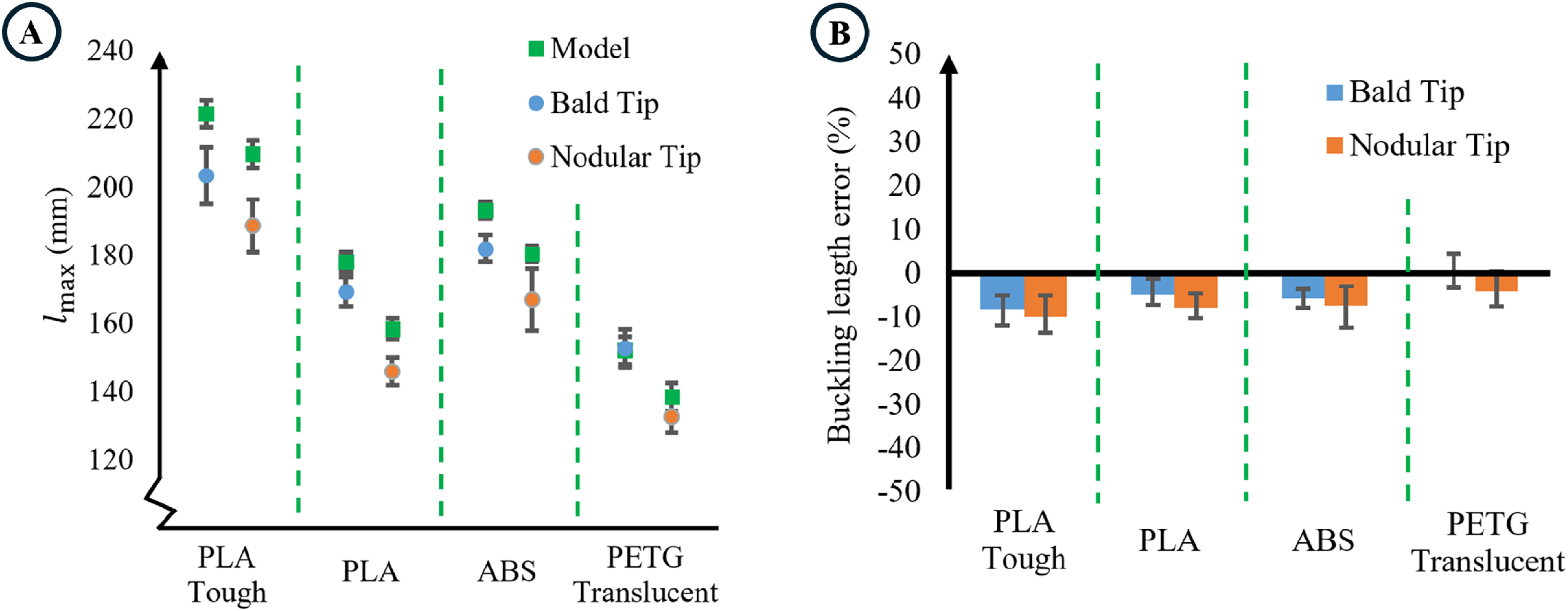
The tested result and error are shown in Figure 5. By pulling rods out from the rubber sheets under specific length (20 mm for bald tips and 100 mm for nodular tip), the resistance was measured through a dynamometer. The insertion length of the corresponding material was then tested to keep a consist rubber sheet height. The maximum insertion length for each type of rod was tested three times, and error bar was obtained considering both the deviation of the tested length and the error from the supplied Young’s modulus. The results should not be compared directly across materials because the applied friction conditions differed between the tests.
Result of the critical bulckling length test. a: Test results and b: Errors.

Figure 5. Long description
Two graphs depict the results of a critical buckling length test. Panel A: A scatter plot shows the maximum buckling length (I max) in millimeters on the vertical axis and different materials (PLA Tough, PLA, ABS, PETG Translucent) on the horizontal axis. The plot includes data points for three series: Model (green squares), Bald Tip (blue circles), and Nodular Tip (orange circles). Each material group shows variations in I max for the different tip types. Panel B: A bar graph displays the buckling length error percentage on the vertical axis and the same materials on the horizontal axis. The graph includes two data series: Bald Tip (blue bars) and Nodular Tip (orange bars). The error percentages vary for each material and tip type, with some errors being positive and others negative.
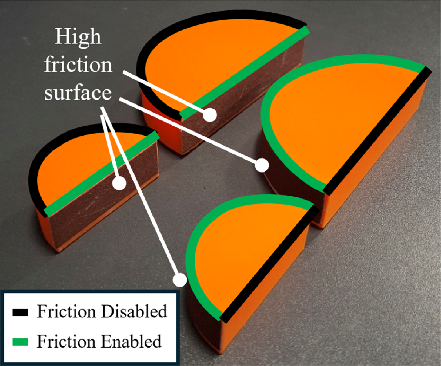
Objects for the test setup. Additional surface is locally attached for a considerable friction.

4.2. Validation of resistance
Friction tests were conducted using the same rods. As shown in Figure 6, semi-circular objects (diameter 30 and 60 mm) fabricated by 3D printing were used as obstacles and fixed onto the tabletop. Treating the friction from the object surface negligible (friction disabled), we use fine coarse paper as high friction surface to attach at the object surface to enable significant friction. The rod was bent within the environment to conform to the obstacles, and the rod was pulled backwards from the bottom using a dynamometer to measure the tensile force.
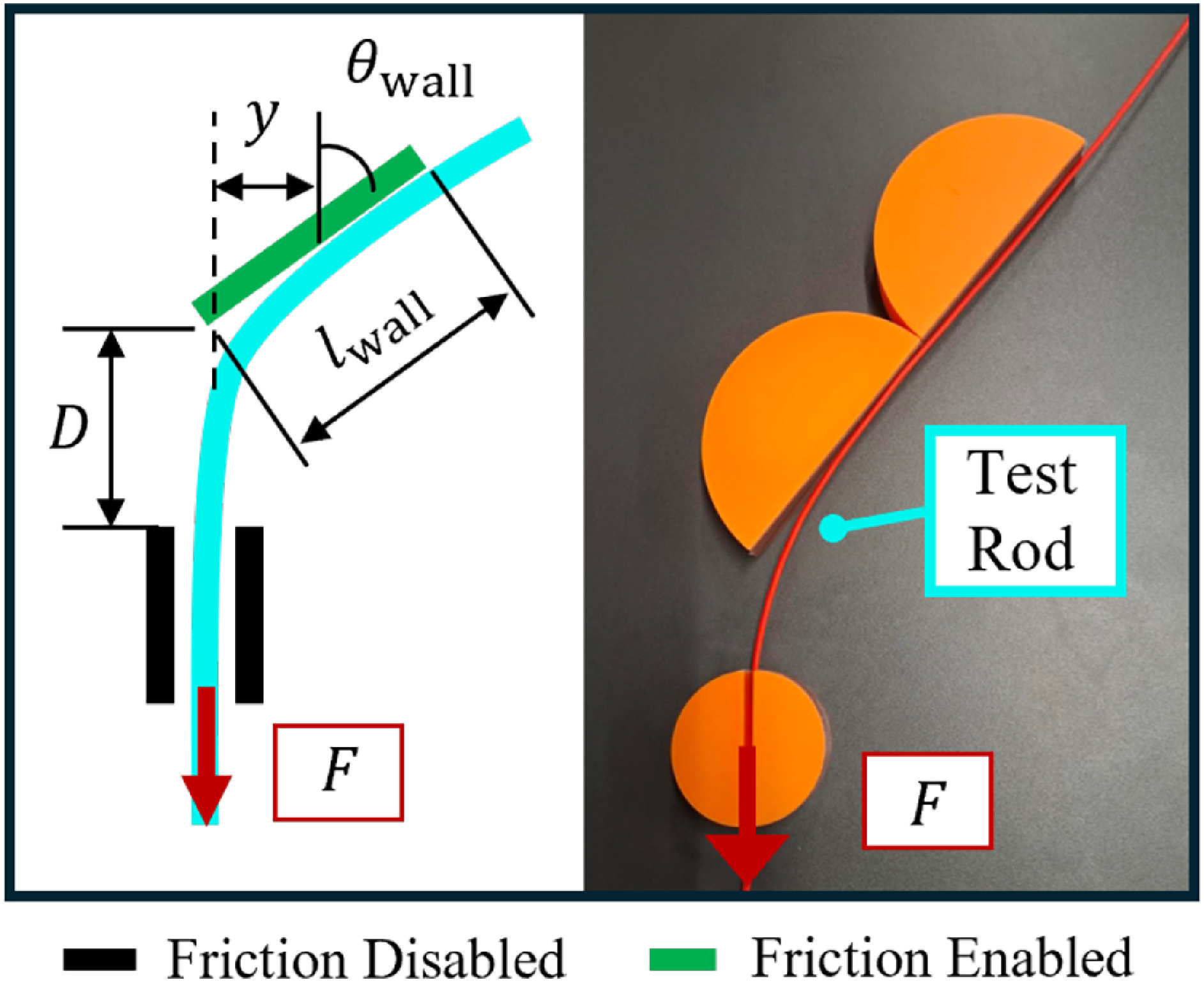
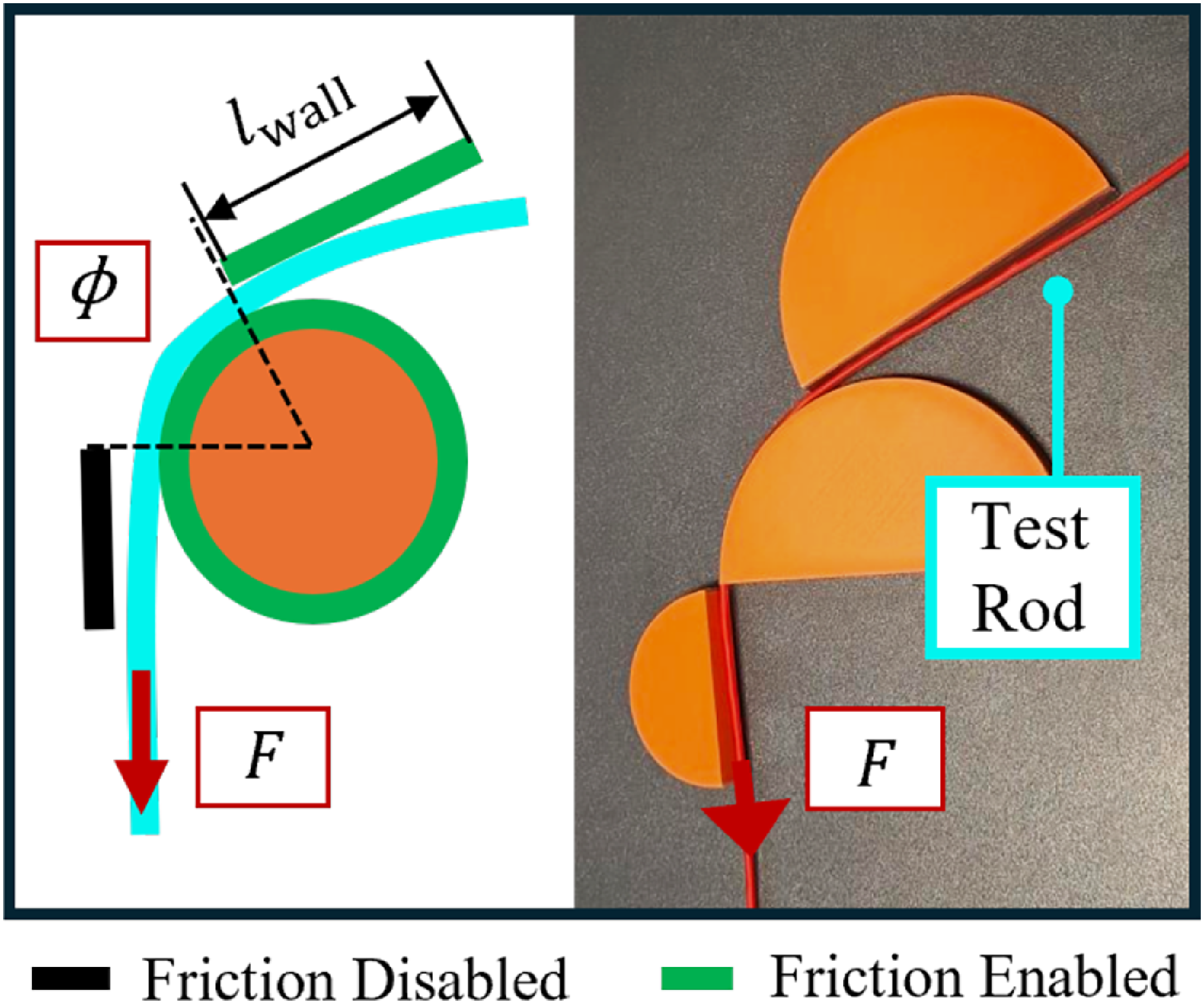
Contact resistance and wrapping resistance were tested respectively in two setups. To prevent mechanical jamming, a clearance of 0.5–1 mm was introduced in all setups relative to the theoretical dimensions. For the contact resistance setup, the rod was in contact with an inclined flat wall to evaluate the axial force induced by wall friction (Figure 7). The starting point of the wall was aligned with the vertical extension line of the rod. The wall inclination angle
 $\theta _{\text{wall}}$
is the controlled variable. The distance
 $D$
between the starting point of the wall and the numerical constraint endpoint of the rod, and the wall length
 $l_{\text{wall}}$
were set as constant.
In the resistance-validation experiments, the rod was pulled from the proximal side using a dynamometer, whereas the resisting contact force was generated distally by the wall or wrapping fixture. The measured dynamometer force therefore corresponds to the proximal force required to overcome a known distal resistance. Consequently, the experimental prediction uses the inverse form of the capstan relation:
 \begin{equation}F_{\text{wall}}=\mu _{\text{wall}}N_{\text{norm}}-N_{\text{axis}}\end{equation}
rather than the forward transmission form in Eq. (6). The positive exponent reflects the direction in which the required force is calculated and does not imply force generation by the wrapping contact.
Setup for the discrete wall contact resistance test. The rod interacts with an inclined wall at angle
 $\theta$
, and the resulting axial force is measured to quantify frictional contact effects.

Figure 7. Long description
Panel A: A schematic diagram showing a rod interacting with an inclined wall. The wall is at an angle theta_wall, with dimensions D, l_wall, and y labeled. The rod is shown with and without friction enabled, indicated by different colors. A force F is applied downward on the rod. Panel B: A photograph of the actual test setup with an orange test rod interacting with an inclined wall. The force F is applied downward on the rod, and the setup is labeled accordingly.
For each tested material, the wall-contact friction coefficient
 $\mu _{\text{wall}}$
was calibrated using the measured pulling force at the reference wall inclination of
 $\mu _{\text{wall}}=40^{\circ}$
. The geometric parameters
 $l_{\text{cant}}$
, y, and
 $\theta _{\mathrm{tip}}$
were first obtained from the prescribed test geometry following the procedure described in Section 3.2. The measured pulling force at
 $40^{\circ}$
was then substituted into Eqs. (9)–(14), and the equations were rearranged to determine
 $\mu _{\text{wall}}$
. Using the reference condition
 $\mu _{\text{wall}}=40^{\circ}$
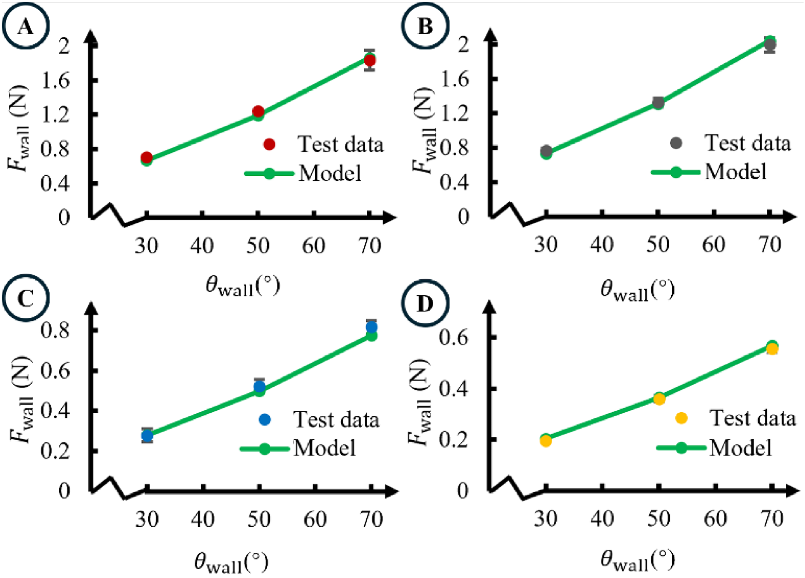
, the calibrated wall-contact friction coefficients were 1.46, 1.42, 1.37, and 1.4 for PLA Tough, PLA, ABS, and PETG, respectively. These coefficients were then held constant when predicting the pulling forces at the remaining wall inclination angles.
The tested result is shown in Figure 8. To keep the resistance within a measurable range,
 $l_{\text{wall}}=120\, \mathrm{mm}$
was set for all the tests,
 $D=60\,\mathrm{mm}$
for PLA tough and PLA, and
 $D=30\,\mathrm{mm}$
for ABS and PETG.
 $l_{\text{cant}}$
and
 $y$
can be obtained based on constant curvature assumption. It should be noted that the results are not intended for direct inter-material comparison because the geometric distance D differed between the tests.
Result of the contact resistance test with different materials. a: Result of PLA tough, b: Result of PLA, c: Result of ABS, and d: Result of PETG.

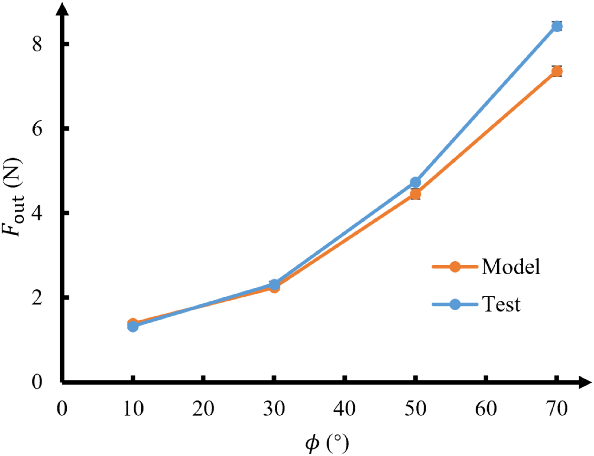
The wrapping contact resistance experiment (Figure 9) examined the relationship between the wrapping angle and the force required to transmit a prescribed distal resistance through the contact. The straight frictional wall generated the distal resistance, while the dynamometer measured the corresponding proximal pulling force. The cylindrical obstacle was positioned tangentially to the straight wall, and its angular position defined the angle
 $\phi$
, which is also the wrapping angle of the rod.
Setup for the wrapping contact resistance test. The rod wraps around a cylinder with controlled angle
 $\varnothing$
, and the transmitted tensile force is measured to assess friction loss.

PLA tough was selected as the tested material and the result is shown in Figure 10.
 $l_{\text{wall}}=60\,\mathrm{mm}$
was set for the test. The wrapping-contact coefficient
 $\mu _{\mathrm{c}}$
was calibrated using the measured forces at the reference wrapping angle of
 $\phi =20^{\circ}$
and disabled wall contact resistance. The force measured without friction on the cylindrical surface was taken as the reference distal force
 $F_{\mathrm{o}ut}$
, while the dynamometer reading obtained with the frictional wrapping surface provided the corresponding proximal pulling force
 $F_{\mathrm{i}n}$
. The coefficient was calculated by rearranging the inverse capstan relation:
 \begin{equation}\mu _{\mathrm{c}}=\ln {\left(F_{\mathrm{i}n}/F_{\mathrm{o}ut}\right)} /\phi\end{equation}
The value identified at
 $\phi =20^{\circ}$
was subsequently used without further adjustment to predict the pulling force at the remaining wrapping angles. Using the reference wrapping angle
 $\phi =20^{\circ}$
, the calibrated wrapping-contact friction coefficient for the PLA Tough rod was 1.03. The wrapping angle was expressed in radians when evaluating the capstan relation. This calibrated coefficient was used without further adjustment to predict the proximal pulling force at the remaining wrapping angles.
The loss-free tensile force was directly measured experimentally when the cylindrical object was not covered with sandpaper.
Specifications of the implemented extra-long continuum manipulator.

Table II. Long description
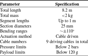
A table with two columns and nine rows. The first column is labeled Parameter and the second column is labeled Specification. Row 1: Total length, 8.2 m. Row 2: Total mass, less than 2 kg. Row 3: Segment lengths, up to 1 m. Row 4: Section diameters, 25 mm. Row 5: Bending ranges, 110 degrees. Row 6: Actuation method, cable driven. Row 7: Cable numbers, 9 driving cables in total. Row 8: Pressure limits, below 2 bars. Row 9: Payload limits, below 120 g.
Result of the wrapping resistance test.

Each experimental condition in the wall-contact and wrapping-contact tests was repeated three times. The values presented in Figures 8 and 10 are the mean measured forces, and the error bars represent the variability across the three repeated measurements. The maximum error-bar magnitude among all reported conditions was 0.16 N. Because this value is small relative to the force ranges shown in the figures, several error bars are not readily distinguishable at the plotted scale.
5. Field-representative mock-up testing and in-field deployment
The manipulator described in Section 2 has been deployed in a nuclear decommissioning cell at NRS Dounreay for vision and radiation inspection. Before deployment in the active environment, full-scale mockup tests were conducted to verify the deployment procedure and train the site engineers. The mockup has been setup based on the supplied drawing and the feedback from Dounreay engineers. Table II summarises the key specification of the prototyped manipulator.
5.1. Field-representative mock-up testing
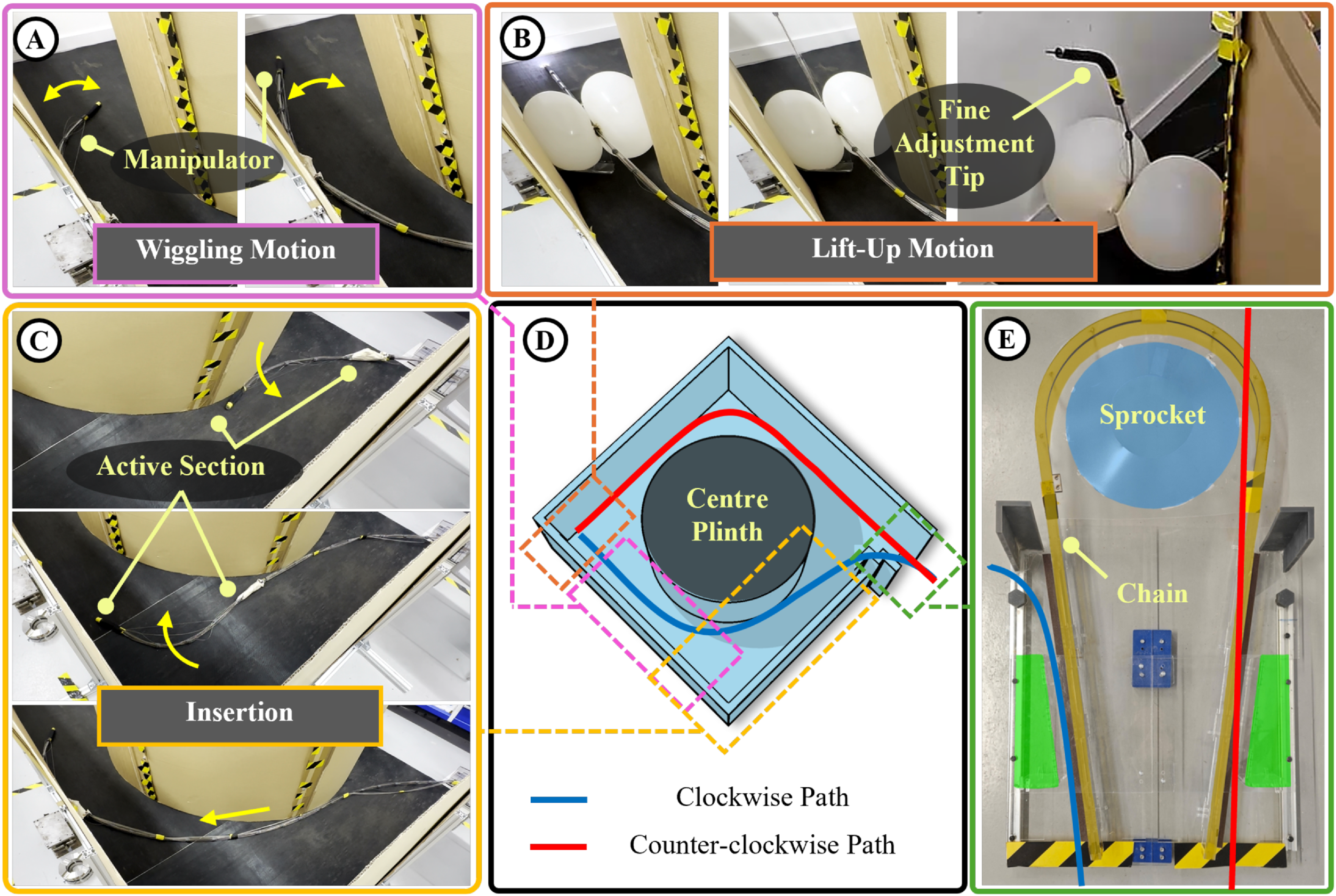
As shown in Figure 11, the mockup reconstructed the configuration of the inspecting cell and facilities that will potentially interact with the manipulator during the deployment. The cell is around 3.5 m × 3.5 m and the maximum travelling distance is around 7.5 m. The cell consists of a ∼
 $\phi 2\,\mathrm{m}$
plinth to support a ∼
 $\phi 3\,\mathrm{m}$
turning table seating right above and previously being controlled with a motor transmitted through a chain and sprocket. By taking the worst condition, the friction of the ground surface was increased by placing an anti-slippery rubber mat on the floor. As the first step of the deployment, the manipulator is required to pass through the gap between the chain and wall referred to as the entrance. The entrance configuration (Figure 11d) comprises a chain-driven sprocket system positioned close to the cell wall, with angle irons and bolted structural elements forming a narrow and partially constrained access gap.
Setup and deployment in the mockup. a: Manipulator wiggling motion for compression stress releasing, b: Lift-up motion at the target location, c: Manipulator key posture during insertion, d: Arrangement of the mockup, and e: Entrance of the mockup.

Figure 11. Long description
Panel A: A series of images showing the manipulator performing a wiggling motion to release compression stress. Panel B: Images depicting the lift-up motion of the manipulator at the target location, with a fine adjustment tip visible. Panel C: Images illustrating the key posture of the manipulator during insertion, highlighting the active section. Panel D: A schematic diagram of the mockup arrangement, showing the centre plinth and paths for clockwise and counter-clockwise movements. Panel E: An image of the mockup entrance, featuring a sprocket and chain mechanism.
The manipulator accessed the cell through gaps between the chain and the concrete wall, covering the whole ground floor inspection through a clockwise and a counter-clockwise path. While the counter-clockwise path requires a longer travelling distance and slightly tighter gap to climb over the chain and navigate into the cell (red path in Figure 11d), the clockwise path holds a larger challenge with more bends, which is the risk of causing insertion-induced buckling.
On the clockwise path, the manipulator enters through the gap between the lower-side chain (blue path in Figure 11d) and the side wall. Before reaching the angle iron, the manipulator left bent its fine adjustment, which provides effective steering within confined space where requires small bending radius. By keeping feed-in the body of the manipulator after the left turn, the manipulator enters the interior of the cell. The active section then provided a left steering (Figure 11c), offering a 4.5 times larger searching area compared with the steering from the fine adjustment tip. This allows the manipulator to reach the centre plinth and passively guide the body leftwards and finally reach bottom corner. The active section of advancing the manipulator was then prepared for the coming contact with the wall of the cell (middle figure in Figure 11d).
Further advancement enables the manipulator to utilise the supporting force from the wall to guide its body to bend, as illustrated in Figure 11d. However, when manipulator receives a large payload which approaches the theoretical limit, the manufacturing imperfection of the manipulator structure still leads to insufficient axial stiffness, which can no longer transmit the feed-in force effectively, leading to an insertion-induced buckling failure.
Wiggling the manipulator’s head during the feed-in can push the actual buckling condition closer to the theoretical situation (Figure 11a). This motion converts static friction into dynamic friction while releasing the elastic potential energy stored in the body, thereby relieving the stress accumulation over the body section. The body section achieves a nearly 90° bend after repeating several times of the wiggling. Continued advancement then allows the manipulator to reach the target position, ready for the lift-up motion and further inspection.
5.2. In-field deployment
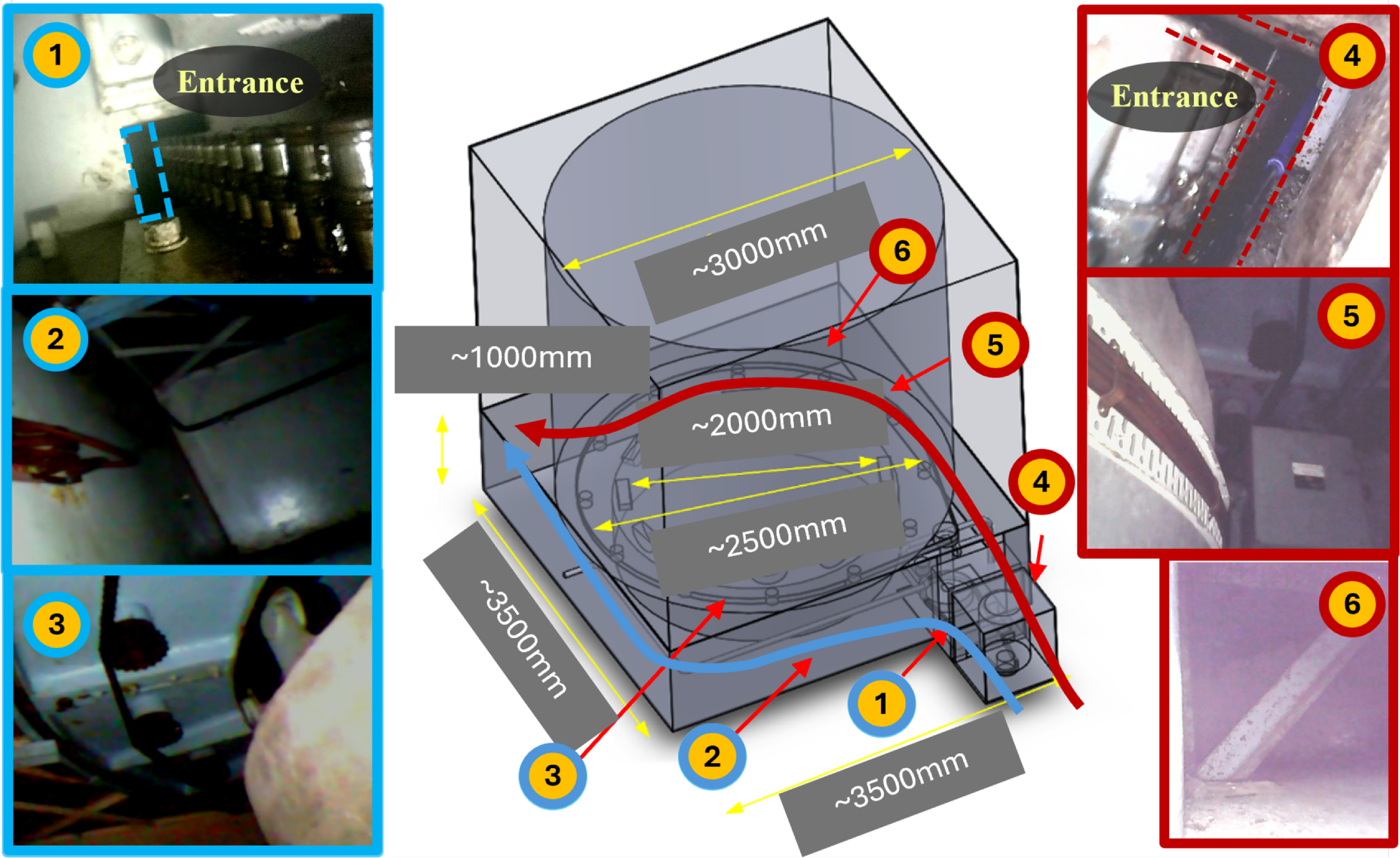
Following te mock-up training, five deployments were conducted independently by the Dounreay engineering team in the active nuclear cell (Figure 12 – Images 1–6 are some of the video crops taken from the front borescope). Thanks to the higher power LED, the illumination lights up the fully dark environment and provides sufficient brightness for vision inspection.
Deployment in a real nuclear hot cell. Images 1–6 are have been captured by the camera mounted in the manipulator. The left and right entrances are marked in blue and red dashed lines.

All five deployments completed their planned operational objectives. The system required no more than 20 min for on-site assembly and preparation. Each insertion, inspection, and data-collection operation were completed within 20 min.
A deployment was classified as successful when the manipulator reached the planned target region, established a stable inspection configuration, acquired the required sensor data, and was subsequently retrieved without structural damage or operational intervention inside the cell.
Approximately 7.5 m of the 8.2 m manipulator was inserted during the longest deployment. At the target location, the stabilising section supported a lift-up height of approximately 0.67 m while carrying the borescope and the 70 g radiation sensor. No loss of retrieval capability, structural failure, or unrecoverable buckling occurred during the five active-cell deployments.
Before active-cell deployment, the stability framework was applied to the representative mock-up paths using the estimated insertion length, contact sequence, and resistance parameters. Paths for which the estimated proximal insertion-force demand remained below the predicted buckling limit were classified as feasible. Path configurations approaching or exceeding the predicted limit were treated as high risk and were either modified or excluded from the active-cell procedure.
The selected feasible paths were subsequently completed successfully in the mock-up and during the five active-cell deployments. This outcome provides practical corroboration that the framework was suitable for conservative path screening. However, deliberate deployment along paths classified as high risk was not permitted because an insertion-induced buckling failure could have compromised retrieval and contamination control. The field trials therefore verify successful operation within the predicted feasible region but do not constitute a controlled validation of both feasible and infeasible path classifications.
6. Discussion and conclusion
This work presented a modular extra-long continuum manipulator for hybrid deployment paths containing confined entrances, surface-supported or loosely constrained regions, and an elevated inspection target. The principal system-level contribution is the separation of long-range insertion from local lift-up stabilisation: the self-recoverable passive body permits advancement without continuous lateral confinement, while the independently actuated dual-balloon unit is activated at the target to support the lift-up operation. The contribution therefore extends beyond increasing the available reach or adapting an existing manipulator to a nuclear environment.
The second contribution is a deployment-oriented, solver-free stability assessment that combines the principal resistance modes encountered along a hybrid path. Rather than predicting the complete deformed configuration, the framework estimates a conservative insertion-force demand and corresponding buckling margin. It is therefore intended to support structural selection and path screening before deployment.
The manipulator was successfully deployed in a nuclear decommissioning hot cell at NRS Dounreay, UK. The field operation confirmed the practicality of the proposed system and supported the applicability of the conservative stability envelope under real deployment conditions.
Future work will focus on enhancing the hardware capabilities of the system to further extend its operational performance. In particular, efforts will be directed towards increasing payload capacity, extending the achievable navigation distance, and improving lift-up height through advancements in structural stiffness and load-bearing design. These developments are also expected to improve robustness during deployment, especially when operating along more demanding paths that require higher insertion forces.
In addition, future research will investigate the behaviour of the long passive body under large-angle bending conditions, where configuration bifurcation and related instabilities may arise. Control strategies will be developed to identify and manage such configuration transitions during insertion and navigation, with the aim of ensuring stable and predictable deployment in complex environments.
Overall, the results indicate that reliable long-reach continuum deployment in hybrid industrial environments requires the joint consideration of structural design, conservative stability estimation, operational simplicity, and recovery planning. The proposed system and assessment approach provide a practical basis for future continuum manipulators operating in harsh industrial settings.
Acknowledgements
The authors would like to acknowledge the support received from the University of Nottingham; RAICo project; Game Changers project (GC651); and the UKRI RAIN + project (EP/W001128/1). The authors used AI-assisted tools (ChatGPT) solely for English language editing and grammar checking. All scientific content, ideas, and conclusions are entirely the authors’ own.
Author contributions
J.C. Chang conceived and designed the study. J.C. Chang, J. Liu, and H. Dai conducted data gathering. J.C. Chang performed statistical analyses. J.C. Chang, J. Liu, H. Dai, X. Wang, and D. Axinte wrote the article.
Financial support
The authors declare no financial support.
Competing interests
The authors declare no conflicts of interest exist.
Ethical standards
Not applicable.
 θ
 ∅