1. Introduction
Spatial parallel manipulators should be balanced properly, that is, stable in all configurations. Different balancing mechanisms were developed by researchers two decades back. Examples are counterweight [Reference Yilmaz and Anlas1, Reference Woo, Seo and Yi2], pneumatic or hydraulic cylinders [Reference Wildenberg3], mechanical balancing like gear train [Reference Martini, Troncossi, Carricato and Rivola4], helical/torsional spring [Reference Agrawal and Fattah5, Reference Juang, Jhuang and Chen6], and cam mechanism [Reference Leblond and Gosselin7]. Most of the above-mentioned balancing mechanisms were used for planar mechanisms. However, when it comes to spatial mechanisms where the center of mass is high above the platform, parallelogram mechanisms [Reference Ebert-Uphoff, Gosselin and Laliberte’8, Reference Ebert-Uphoff and Johnson9] are used for gravity compensation. Arakelian [Reference Arakelian and Guegan10] used the pantograph mechanism, a special case of parallelogram mechanism, to address the balancing of a spatial parallel manipulator. A geometric method for the static balancing of spatial mechanisms was proposed by Wang [Reference Wang and Kong11]. Dynamic balancing methods were categorized as balancing before kinematic synthesis and balancing after the design by Zhang [Reference Wei and Zhang12].
All the above-mentioned balancing mechanisms solely address the balancing issue. While incorporating balancing mechanisms, an increase in the mass of the assembly cannot be avoided with the above methods, and hence the actuator force requirements are increased subsequently. If the mass of the balancing mechanism is reduced, the damping of forces becomes challenging. Hence, while designing a balancing mechanism, damping needs to be also taken into account. This article proposes a lightweight balancing mechanism that does not sacrifice damping. In addition to load balancing, it can also address force requirements.
1.1. Three-legged decoupled parallel manipulators
Decoupled parallel manipulators with three legs have two active joints and two passive joints in each leg, leading to six actuators and hence 6-degrees of freedom (DOF). For example, the first two joints are actuated in each leg in the case of a 3-prismatic-prismatic-revolute-spherical (PPRS) manipulator.
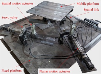
The first actuator from each leg collectively produces a 3-DOF planar motion, either translational along the X-Y plane or rotational motion about the Z axis. Similarly, the second actuator from each leg collectively produces a 3-DOF spatial motion which is either translational motion along the Z axis or rotational motion about the X and Y axes (Fig. 1). Hence, the set of actuators that are causing translation in X-Y plane and rotational motion in X-Y plane are grouped as planar motion actuators. Similarly, the set of actuators causing rotational motion about the X and Y axes and translation along the Z axis are grouped as spatial motion actuators [Reference Mangavu and Dash13].
The 3-PPRS parallel manipulator (equipment developed in-house).

The 3-PPRS parallel manipulator without the load-balancing mechanism is shown in Fig. 1. It is a three-legged decoupled parallel manipulator having a fixed platform connected to a mobile platform through three identical actuator legs. Each leg comprises a horizontal motion actuator, a vertical motion actuator, and a link with a revolute joint at one end and a spherical joint at the other.
Such manipulators are called decoupled because the manipulator can exhibit planar and spatial motion separately, using a limited number of actuators (three actuators in each case). The role of transmission links in this parallel manipulator is mainly for transmitting the planar motion in the X-Y plane. However, the planar links cause cantilever action, which affects the stiffness and result in inaccuracies due to the thrust forces on the mobile platform. It is a common load-balancing challenge experienced by planar manipulators, similar to the load-balancing issue in serial manipulators.
Hence, the links are made spatial as in the case of general spatial manipulators (Stewart platform or delta manipulators), where the transmission links elevate the mobile platform from the base platform. The spatial links are created without changing the axes of the joints. It means the force transmission will still be retained in the X-Y plane (Fig. 1). Due to spatial links, the improvement in translational stiffness was reported in [Reference Ganesh, Dash, Venkitachalam and Shrinithi14] despite the reduced force transmission in the X-Y plane.
However, such inclusion of spatial links was insufficient and resulted in deflection due to the heavy payload. The deflection of the entire assembly of the developed in-house prototype is displayed in Fig. 2. Such deflections can be vastly subdued by removing the manufacturing and assembly tolerances. However, the loading impact affecting the stiffness is evident, causing strain on the actuators and producing errors due to lateral deformations of actuator assemblies [Reference Ammanagi, Poornima, Sera and Sunder15].
(a) Deflection of entire assembly on the application of external load on top of the mobile platform of 3-PPRS manipulator and (b) entire assembly without external load on mobile platform-without deflection (prototype developed in-house).

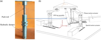
From the above argument and based on the discussion in Section 1.1, it can be well established that any improvement in the method of balancing upsurges the torque of the actuator. To address this issue, it has been proposed to add a passive damper in the load-balancing UPS leg (Fig. 3), which provides force compensation along with load balancing. While adding a damper element with reduced mass, it is essential to verify the structural analysis results.
(a) Festo shock absorber as a passive damper element and (b) the 3-PPRS manipulator with passive damper element.

A passive damper element is used for the prismatic link in the UPS configuration. Adding the damper element to the parallel manipulator resembles a semi-active damper in the suspension system [Reference Omar, El-kassaby and Abdelghaffar16]. The main functioning difference between an actuator in the suspension system and the damper in parallel manipulators is as follows. The role of the actuator in the suspension system is to provide timely reaction forces to counteract the input forces and additionally dissipates part of the vibration energy. A damper’s main role in a shake table is to suppress/dissipate vibrations due to reactive forces and additionally provide counteracting forces to the gravity load. However, the forces are non-linear in the case of the damper.
Many configurations of serial structures can be utilized as a load-balancing leg [Reference Lu and Hu17]. The universal-prismatic-universal (UPU) leg is preferred among such configurations due to minimal interference and avoids singularities. However, the drawback of UPU leg assembly is that it constrains the workspace and the DOF [Reference Wang and Gosselin18]. Hence, a UPS configuration is preferred, and singularity point in the workspace is carefully avoided [Reference Zhang, Zhao and Jin19].
In what follows, the Denavit–Hartenberg methodology for the UPS leg in Section 2 followed by the demonstration of stiffness addition to the parallel mechanism through Jacobian analysis of the UPS leg configuration in Section 3. Structural analysis is also done to verify the improvement in the load balancing, and the results are compared with three different architectures of the 3-PPRS parallel manipulator in Section 4. The impact of the damper mechanism on the passive leg is studied using detailed dynamic system modeling in Section 5. The system modeling is done for a single-leg assembly to illustrate the concept.
2. D-H methodology
In this section, the inverse kinematics is solved using the D-H methodology. The geometric description of the single leg and a UPS leg is shown in Fig. 4a. The d1i and d2i are the displacements of the linear actuators, and l1 is the link length of the transmission link.
 $\theta _{1i}$
and
 $\theta _{2i}$
are the angle of rotational joints C and D, respectively.
Frame assignment for (a) a single leg and (b) passive load-balancing UPS leg.

The frame assignment for the passive load-balancing UPS leg is shown in Fig. 4b. The first universal joint is assigned with frame 0 and frame 1, followed by the prismatic joint assigned with frame 2, followed by the second universal joint, which is assigned with frames 3 and 4. The final frame 5 is assigned to the mobile platform. There are five joints serially connected, starting from two rotational joints with the same origin, then a prismatic joint and two rotational joints with the same origin. The respective joint axes
 $x_{n}$
and
 $z_{n}$
, are assigned to the joints. The angle for the rotational joint is
 $\theta _{n}$
, and the displacement for the linear joint is
 $d_{n}$
. The D-H link and joint parameters are listed in Table I.
D-H table for passive UPS leg of the 3-PPRS manipulator.

The following equation gives the basic link transformation matrix,
 \begin{equation}{ }^{i-1}{T_{i}}{} = \left[\begin{array}{c@{\kern+12pt}c@{\kern+12pt}c@{\kern+12pt}c} C\theta _{i} & -{S\theta _{i}}C\alpha _{i} & S\theta _{i}S\alpha _{i} & {a_{i}}C\theta _{i}\\ S\theta _{i} & C\theta _{i}C\alpha _{i} & -C\theta _{i}S\alpha _{i} & {a_{i}}S\theta _{i}\\ 0 & S\alpha _{i} & C\alpha _{i} & d_{i}\\ 0 & 0 & 0 & 1 \end{array}\right]\end{equation}
The D-H transformation matrices are derived by substituting the D-H parameters in the fundamental link transformation matrix. The D-H transformation matrices are as follows:
 \begin{equation}{ }^{0}{T_{3}}{}\,{=}\,{ }^{0}{T_{2}}{}\times { }^{2}{T_{3}}{}\,{=}\,\left[\begin{array}{c@{\kern+12pt}c@{\kern+12pt}c@{\kern+12pt}c} C\theta _{1} & -{S\theta _{1}}C\theta _{2} & S\theta _{1}S\theta _{2} & -{S\theta _{1}}C\theta _{2}d_{3}\\ S\theta _{1} & C\theta _{1}C\theta _{2} & -C\theta _{1}S\theta _{2} & C\theta _{1}C\theta _{2}d_{3}\\ 0 & S\theta _{2} & C\theta _{2} & S\theta _{2}d_{3}\\ 0 & 0 & 0 & 1 \end{array}\right]\end{equation}
The stiffness analysis was carried out on the manipulator in its home position, with the mobile platform at zero orientation. In other words, without any tilt. As a result, the
 $\theta _{4};\, \theta _{5}$
; and
 $\theta _{6}$
influences on end-effector orientation were considered to be zero.
 \begin{equation}{ }^{0}{T_{6}}{}\,{=}\,{ }^{0}{T_{3}}{}\times { }^{3}{T_{6}}{} = \left[\begin{array}{c@{\kern+12pt}c@{\kern+12pt}c@{\kern+12pt}c} S\theta _{1}S\theta _{2} & C\theta _{1} & -S\theta _{1}C\theta _{2} & -{S\theta _{1}}C\theta _{2}d_{3}\\ -C\theta _{1}S\theta _{2} & S\theta _{1} & C\theta _{1}C\theta _{2} & C\theta _{1}C\theta _{2}d_{3}\\ C\theta _{2} & 0 & S\theta _{2} & S\theta _{2}d_{3}\\ 0 & 0 & 0 & 1 \end{array}\right]\end{equation}
The directions of the joint axes,
 $P_{i-1}$
, derived using the equation
 $P_{i-1}={ }^{0}{R_{i-1}}{}\left[\begin{array}{c} 0\\ 0\\ 1 \end{array}\right]$
, are as follows:
The rotation matrix,
 \begin{equation}{ }^{0}{R_{0}}{}\,{=}\,\left[\begin{array}{c@{\kern+12pt}c@{\kern+12pt}c} 1 & 0 & 0\\ 0 & 1 & 0\\ 0 & 0 & 1 \end{array}\right]{;}\,P_{0}={ }^{0}{R_{0}}\widehat{u}={ }^{0}{R_{0}}{}\left[\begin{array}{c} 0\\ 0\\ 1 \end{array}\right]=\left[\begin{array}{c} 0\\ 0\\ 1 \end{array}\right];\end{equation}
 \begin{equation}{ }^{0}{R_{1}}{}\,{=}\,\left[\begin{array}{c@{\kern+12pt}c@{\kern+12pt}c} -S\theta _{1} & 0 & C\theta _{1}\\ C\theta _{1} & 0 & S\theta _{1}\\ 0 & 1 & 0 \end{array}\right]{;}\,P_{1}={ }^{0}{R_{1}}{}\widehat{u}={ }^{0}{R_{1}}{}\left[\begin{array}{c} 0\\ 0\\ 1 \end{array}\right]=\left[\begin{array}{c} C\theta _{1}\\ S\theta _{1}\\ 0 \end{array}\right];\end{equation}
 \begin{equation}{ }^{0}{R_{2}}{}\,{=}\,\left[\begin{array}{c@{\kern+12pt}c@{\kern+12pt}c} S\theta _{1}S\theta _{2} & C\theta _{1} & -{S\theta _{1}}C\theta _{2}\\ -C\theta _{1}S\theta _{2} & S\theta _{1} & C\theta _{1}C\theta _{2}\\ C\theta _{2} & 0 & S\theta _{2} \end{array}\right]{;}\,P_{2}={ }^{0}{R_{2}}{}\widehat{u}={ }^{0}{R_{2}}{}\left[\begin{array}{c} 0\\ 0\\ 1 \end{array}\right]=\left[\begin{array}{c} -{S\theta _{1}}C\theta _{2}\\ C\theta _{1}C\theta _{2}\\ S\theta _{2} \end{array}\right];\end{equation}
 \begin{equation}{ }^{0}{R_{3}}{}\,{=}\,\left[\begin{array}{c@{\kern+12pt}c@{\kern+12pt}c} C\theta _{1} & -{S\theta _{1}}C\theta _{2} & S\theta _{1}S\theta _{2}\\ S\theta _{1} & C\theta _{1}C\theta _{2} & -C\theta _{1}S\theta _{2}\\ 0 & S\theta _{2} & C\theta _{2} \end{array}\right];\, P_{3}={ }^{0}{R_{3}}{}\widehat{u}={ }^{0}{R_{3}}{}\left[\begin{array}{c} 0\\ 0\\ 1 \end{array}\right]=\left[\begin{array}{c} S\theta _{1}S\theta _{2}\\ -C\theta _{1}S\theta _{2}\\ C\theta _{2} \end{array}\right];\end{equation}
 \begin{equation}{ }^{0}{R_{4}}{}\,{=}\,\left[\begin{array}{c@{\kern+12pt}c@{\kern+12pt}c} -{S\theta _{1}}C\theta _{2} & S\theta _{1}S\theta _{2} & C\theta _{1}\\ C\theta _{1}C\theta _{2} & -C\theta _{1}S\theta _{2} & S\theta _{1}\\ S\theta _{2} & C\theta _{2} & 0 \end{array}\right]{;}\,P_{4}={ }^{0}{R_{4}}{}\widehat{u}={ }^{0}{R_{4}}{}\left[\begin{array}{c} 0\\ 0\\ 1 \end{array}\right]=\left[\begin{array}{c} C\theta _{1}\\ S\theta _{1}\\ 0 \end{array}\right];\end{equation}
 \begin{equation}{ }^{0}{R_{5}}{}\,{=}\,\left[\begin{array}{c@{\kern+12pt}c@{\kern+12pt}c} S\theta _{1}S\theta _{2} & C\theta _{1} & -{S\theta _{1}}C\theta _{2}\\ -C\theta _{1}S\theta _{2} & S\theta _{1} & C\theta _{1}C\theta _{2}\\ C\theta _{2} & 0 & S\theta _{2} \end{array}\right]{;}\,P_{5}={ }^{0}{R_{5}}{}\widehat{u}={ }^{0}{R_{5}}{}\left[\begin{array}{c} 0\\ 0\\ 1 \end{array}\right]=\left[\begin{array}{c} -{S\theta _{1}}C\theta _{2}\\ C\theta _{1}C\theta _{2}\\ S\theta _{2} \end{array}\right];\end{equation}
The position vectors
 ${ }^{i-1}{P_{6}}{}$
, derived by applying the equation,
 ${ }^{n}{P_{i}}{}={ }^{0}{T_{i}}{}O_{i}-{ }^{0}{T_{n}}{}O_{i}$
, are listed below
 \begin{equation}{ }^{0}{P_{6}}{}={ }^{0}{T_{6}}{}O_{6}-{ }^{0}{T_{0}}{}O_{6}=\left[\begin{array}{c} -{S\theta _{1}}C\theta _{2}d_{3}\\ C\theta _{1}C\theta _{2}d_{3}\\ S\theta _{2}d_{3}\\ 1 \end{array}\right]-\left[\begin{array}{c} 0\\ 0\\ 0\\ 1 \end{array}\right]=\left[\begin{array}{c} -{S\theta _{1}}C\theta _{2}d_{3}\\ C\theta _{1}C\theta _{2}d_{3}\\ S\theta _{2}d_{3}\\ 0 \end{array}\right];\end{equation}
 \begin{equation}{ }^{1}{P_{6}}{}={ }^{0}{T_{6}}{}O_{6}-{ }^{0}{T_{1}}{}O_{6}=\left[\begin{array}{c} -{S\theta _{1}}C\theta _{2}d_{3}\\ C\theta _{1}C\theta _{2}d_{3}\\ S\theta _{2}d_{3}\\ 1 \end{array}\right]-\left[\begin{array}{c} 0\\ 0\\ 0\\ 1 \end{array}\right]=\left[\begin{array}{c} -{S\theta _{1}}C\theta _{2}d_{3}\\ C\theta _{1}C\theta _{2}d_{3}\\ S\theta _{2}d_{3}\\ 0 \end{array}\right];\end{equation}
The Jacobian matrix does not require the position vector
 ${ }^{2}{P_{6}}{}$
. Because it corresponds to the prismatic joint, only the direction of the joint axis
 $P_{2}$
is required.
Also,
 \begin{equation}{ }^{3}{P_{6}}{}={ }^{4}{P_{6}}{}={ }^{5}{P_{6}}{}=\left[\begin{array}{c} 0\\ 0\\ 0 \end{array}\right];\end{equation}
3. Stiffness analysis using Jacobian matrix
The Jacobian matrix for a manipulator with non-planar links is obtained using the screw theory principle. The input/actuator velocities are transformed to the end-effector output velocity using a Jacobian velocity matrix. The Jacobian matrix can also be used to find singular configurations of the manipulator in which it gains one or more DOF.
The end-effector’s twist is related to the joint rate vector
 $\dot{\boldsymbol{\theta}}$
by
 \begin{equation}J\dot{\boldsymbol{\theta}}=t\end{equation}
 \begin{equation} \dot{\boldsymbol{\theta}}=\left[\begin{array}{c@{\kern+12pt}c@{\kern+12pt}c@{\kern+12pt}c@{\kern+12pt}c@{\kern+12pt}c} \dot{d_{1i}} & {\dot{d_{2i}}} & \dot{\theta _{1i}} & \dot{\theta _{4i}} & \dot{\theta _{5i}} & \dot{\theta _{6i}} \end{array}\right]^{T};i \text{denotes leg }i, t=\left[\begin{array}{c} \omega \\ \dot{\boldsymbol{c}} \end{array}\right] \end{equation}
where J is the screw-based velocity Jacobian matrix for UPS configuration
 \begin{equation} J=\left[\begin{array}{c@{\kern+12pt}c@{\kern+12pt}c@{\kern+12pt}c@{\kern+12pt}c@{\kern+12pt}c} P_{0}\times { }^{0}{P}{}_{6} & P_{1}\times { }^{1}{P}{}_{6} & P_{2} & P_{3}\times { }^{3}{P}{}_{6} & P_{4}\times { }^{4}{P}{}_{6} & P_{5}\times { }^{5}{P}{}_{6}\\ P_{0} & P_{1} & 0 & P_{3} & P_{4} & P_{5} \end{array}\right] \end{equation}
 $P_{i}$
is the joint i’s direction vector.
 ${ }^{n}{P_{i}}{}$
is the position vector pointing from the i
th
joint to the end-effector. The values of position vectors and the direction of joint axes are imported from Section 2 for Jacobian calculations.
For the 1st joint (revolute),
 \begin{equation} J_{1}=\left[\begin{array}{c} P_{0}\times { }^{0}{P}{}_{6}\\ P_{0} \end{array}\right] \end{equation}
 \begin{equation} J_{1}=\left[\begin{array}{c} \left[\begin{array}{c} 0\\ 0\\ 1 \end{array}\right]\times \left[\begin{array}{c} -{S\theta _{1}}C\theta _{2}d_{3}\\ C\theta _{1}C\theta _{2}d_{3}\\ S\theta _{2}d_{3} \end{array}\right]\\[20pt] \left[\begin{array}{c} 0\\ 0\\ 1 \end{array}\right] \end{array}\right]=\left[\begin{array}{c} {-C\theta _{1}}C\theta _{2}d_{3}\\ -S\theta _{1}C\theta _{2}d_{3}\\ 0\\ 0\\ 0\\ 1 \end{array}\right] \end{equation}
The 3rd joint (prismatic),
 \begin{equation} J_{i}=\left[\begin{array}{c} P_{i-1}\\ 0 \end{array}\right];\, J_{3}=\left[\begin{array}{c} \begin{array}{c} -{S\theta _{1}}C\theta _{2}\\ C\theta _{1}C\theta _{2}\\ S\theta _{2} \end{array}\\ 0\\ 0\\ 0 \end{array}\right] \end{equation}
Similarly, the Jacobian for the other joints
 $J_{4},\,J_{5},\,\text{and}\,J_{6}$
is computed.
 \begin{equation}J_{2}=\left[\begin{array}{c} {S\theta _{1}}S\theta _{2}d_{3}\\ -C\theta _{1}S\theta _{2}d_{3}\\ C\theta _{2}d_{3}\\ C\theta _{1}\\ S\theta _{1}\\ 0 \end{array}\right] J_{4}=\left[\begin{array}{c} 0\\ 0\\ 0\\ S\theta _{1}S\theta _{2}\\ -C\theta _{1}S\theta _{2}\\ C\theta _{2} \end{array}\right] ;\, J_{5}=\left[\begin{array}{c} 0\\ 0\\ 0\\ C\theta _{1}\\ S\theta _{1}\\ 0 \end{array}\right] ;\, J_{6}=\left[\begin{array}{c} 0\\ 0\\ 0\\ -{S\theta _{1}}C\theta _{2}\\ C\theta _{1}C\theta _{2}\\ S\theta _{2} \end{array}\right]\end{equation}
The Jacobian matrix for the UPS configuration is given below,
 $J=\left[\begin{array}{c@{\kern+12pt}c@{\kern+12pt}c@{\kern+12pt}c@{\kern+12pt}c@{\kern+12pt}c} J_{1} & J_{2} & J_{3} & J_{4} & J_{5} & J_{6} \end{array}\right]$
 \begin{equation}J_{UPS}=\left[\begin{array}{c@{\kern+12pt}c@{\kern+12pt}c@{\kern+12pt}c@{\kern+12pt}c@{\kern+12pt}c} \begin{array}{c} {-C\theta _{1}}C\theta _{2}d_{3}\\ -S\theta _{1}C\theta _{2}d_{3}\\ 0\\ 0\\ 0\\ 1 \end{array} & \begin{array}{c} {S\theta _{1}}S\theta _{2}d_{3}\\ -C\theta _{1}S\theta _{2}d_{3}\\ C\theta _{2}d_{3}\\ C\theta _{1}\\ S\theta _{1}\\ 0 \end{array} & \begin{array}{c} \begin{array}{c} -{S\theta _{1}}C\theta _{2}\\ C\theta _{1}C\theta _{2}\\ S\theta _{2} \end{array}\\ 0\\ 0\\ 0 \end{array} & \begin{array}{c} 0\\ 0\\ 0\\ S\theta _{1}S\theta _{2}\\ -C\theta _{1}S\theta _{2}\\ C\theta _{2} \end{array} & \begin{array}{c} 0\\ 0\\ 0\\ C\theta _{1}\\ S\theta _{1}\\ 0 \end{array} & \begin{array}{c} 0\\ 0\\ 0\\ -{S\theta _{1}}C\theta _{2}\\ C\theta _{1}C\theta _{2}\\ S\theta _{2} \end{array} \end{array}\right]\end{equation}
3.1. Stiffness map results
The parallel manipulator configuration proposed in this article comprises two main components: the constraining leg, which can be considered a serial (passive), and the 3-PPRS manipulator as a parallel (active) mechanism. As a result, the overall stiffness matrix of the parallel mechanism with a constraining leg can be obtained by adding the stiffness matrices of the parallel and serial mechanisms [Reference Zhang and Gosselin20]. The stiffness matrix for the manipulator, including the UPS constraining leg, is given by,
 \begin{equation}K=K_{UPS}+K_{\textit{parallel}};\end{equation}
where
 \begin{equation} K_{UPS}=\left(J_{UPS}^{\prime}\right)^{-T}K_{dia}\left(J_{UPS}^{\prime}\right)^{-1} \end{equation}
By the principle of the virtual joint method [Reference Pashkevich, Klimchik and Chablat21], the diagonal stiffness matrix
 $K_{dia}$
is given as follows:
 \begin{equation} K_{dia}=diag\left[0,K_{6},0,0,0,0\right] \end{equation}
Within the workspace, the stiffness of the UPS leg
 $K_{UPS}$
in the X-Y plane is determined. The D-H methodology discussed in Section 2 is used to solve the inverse kinematics of the UPS configuration. With the solved UPS parameters (joint angles and displacement), the Jacobian
 $J_{UPS}$
is computed, and hence the stiffness of the UPS leg.
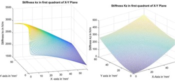
As the spatial motion actuators of the 3-PPRS manipulator are aligned along Z axis, the configuration has high torsional stiffness. Hence, the translational stiffness alone is studied. The stiffness values Kx and Kz in the X-Y plane are plotted in Fig. 5. The stiffness values Kx are high around the region of the home position, and the values are five times larger compared to Kz values. The stiffness in X-axis is a valuable addition to this parallel manipulator (3-PPRS) because the existing parallel manipulator has one of the planar motion actuators aligned along the X-axis. Including UPS leg in the 3-PPRS parallel manipulator will enhance its translational stiffness.
Stiffness plot for Kx and Kz in the X-Y plane for the UPS configuration.

4. Static structural analysis of 3-PPRS parallel manipulator
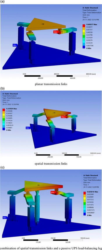
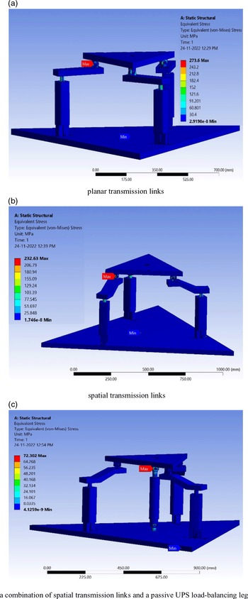
Using ANSYS Workbench software, the structural analysis of the three different 3-PPRS parallel manipulator architectures, namely the 3-PPRS manipulator with planar transmission links, the 3-PPRS manipulator with spatial transmission links, and the 3-PPRS manipulator with spatial transmission links in addition to the passive load-balancing UPS leg, is compared. In this article, the load balancing of the entire manipulator is of prime interest. The vertical hydraulic actuators predominantly carrying the load against gravity are only considered for static structural analysis. On the other hand, the horizontal electrical actuators not carrying any load against gravity are excluded from the analysis, simplifying the computer-aided design (CAD) model.
Three architectures are structurally compared in the static structural analysis [Reference Zhang, Tang, Yan, Cui, Zhang and Yao22] using total deformation and equivalent stress (Von Mises). In the ANSYS Workbench Static Structural tool, the CAD models of the 3-PPRS manipulator are imported from SolidWorks as step files, and the manipulator’s material was set to mild steel (MS). The fixed platform is fastened to the ground, and a load of 5000 N is applied to the center of the mobile platform. The results of the static structural simulation are shown in Figs. 6–7.
The total deformation for the three different architectures of the 3-PPRS manipulator.

The equivalent stress for three different architectures of the 3-PPRS manipulator.

4.1. Results of structural analysis
From Tables II-III, it is clear that compared to the other two 3-PPRS manipulator architectures, the one with both spatial transmission links and a passive load balancing leg has the least total deformation value (0.02581 mm) and the lowest Von Mises equivalent stress (72.30 MPa). The proposed architecture is designed safe because the selected material (MS) has a tensile yield strength of 250 MPa [Reference Jha, Ranjan, Kumar, Sharma and Scholar23]. Thus, the architecture of a 3-PPRS manipulator with spatial transmission links and a passive load-balancing UPS leg is determined to be effective based on the analytical results and selected for manufacturing.
Total deformation of the 3-PPRS manipulator.

Equivalent stress of 3-PPRS manipulator.

5. Dynamic system modeling
Due to the manipulator assembly’s symmetrical nature, a single-leg assembly model is considered [Reference Plummer24]. The specimen model includes the model of the transmission link, push rod, and specimen. Hence, the stiffness of the link, push rod, and specimen are added, as shown in Fig. 8. Specimen stiffness indicates the stiffness of the specimen, connecting link, and the pushrod, and it is represented as
 $K_{sp}$
. Similar is the case with specimen damping
 $C_{sp}$
. The oil column in the cylinder is compressible, and it is represented by a stiffness of
 $K_{a}$
and damping of
 $C_{a}.$
The mechanical model of a single actuator leg and a passive hydraulic cylinder.

The UPS leg is modeled as a passive hydraulic cylinder in Case 1 and a passive damper in Case 2. In the case of a passive damper, it is modeled as a non-linear spring. It means the spring force will be larger at the compressed state and minimum at the extended state [Reference Kluever25]. The spring force is proportional to the displacement by the passive damper, which will be the difference between the total spring length and actual displacement, that is, (
 $z_{max}-z_{t}$
). The mass is considered negligible because of its passive nature.
5.1. Case 1 modeling of UPS leg as a passive hydraulic cylinder
The mechanical model of the single actuator leg and the UPS leg as a passive hydraulic cylinder is shown in Fig. 8. The passive hydraulic cylinder contains a linear spring (
 $K_{b}$
) and damper (
 $C_{b}$
).
The free-body diagram of the above mechanical model is shown in Fig. 9.
The free-body diagram of the mechanical model with UPS leg as a passive hydraulic cylinder.

Upward direction is the positive sign convention for displacements
 $z_{p}$
and
 $z_{t}$
. Summing all external forces with an upward direction as the positive sign convention and applying Newton’s second law, for
 \begin{equation} \text{Mass }(M_{p}): +\uparrow \sum F=-K_{sp}(z_{p}-z_{t})-C_{sp}(\dot{z_{p}}-\dot{z_{t}})-K_{a}z_{p}-C_{a}\dot{z_{p}}+F_{h}=M_{p}\ddot{z_{p}}\end{equation}
 \begin{equation} \text{Mass }(M_{t}): +\uparrow \sum F=K_{sp}(z_{p}-z_{t})+C_{sp}(\dot{z_{p}}-\dot{z_{t}})-K_{sa}z_{t}-C_{sa}\dot{z_{t}}=M_{t}\ddot{z_{t}}\end{equation}
Rearranging these equations with dynamic variables (
 $z_{p}$
and
 $z_{t}$
) on the left-hand side and the input variable
 $F_{h}$
on the right-hand side,
 \begin{equation} M_{p}\ddot{z_{p}}+C_{sp}\left(\dot{z_{p}}-\dot{z_{t}}\right)+K_{sp}\left(z_{p}-z_{t}\right)+K_{a}z_{p}+C_{a}\dot{z_{p}}=F_{h} \end{equation}
 \begin{equation} M_{t}\ddot{z_{t}}+C_{sp}\left(\dot{z_{t}}-\dot{z_{p}}\right)+K_{sp}\left(z_{t}-z_{p}\right)+K_{sa}z_{t}+C_{sa}\dot{z_{t}}=0 \end{equation}
Equations (26) and (27) represent the mathematical model of the single actuator leg and the load-balancing UPS leg. As there are two inertia elements,
 $M_{t}\& M_{p}$
, the model consists of two second-order ordinary differential equations (ODEs). Since both ODEs are coupled, solving one ODE separately from the other is impossible. In Case 1, the model is linear because we have assumed linear stiffness and damper elements. In general, this condition is suitable for an inherently stable system. Intuition tells us that the shake table model is stable and will always return to static equilibrium when input hydraulic force
 $F_{h}$
is stopped.
Writing equation (27) in the Laplace form,
 \begin{equation} M_{t}s^{2}z_{t}+C_{sp}s\left(z_{t}-z_{p}\right)+K_{sp}\left(z_{t}-z_{p}\right)+K_{sa}z_{t}+C_{sa}sz_{t}=0 \end{equation}
 \begin{equation} z_{t}\left(M_{t}s^{2}+C_{sp}s+K_{sp}+K_{sa}+C_{sa}s\right)=-z_{p}\left(-C_{sp}s-K_{sp}\right) \end{equation}
By rearranging the above equation, the relation between pushrod displacement and table displacement is obtained in equation (30),
 \begin{equation} \frac{z_{t}}{z_{p}}=\frac{C_{sp}s+K_{sp}}{\left(M_{t}s^{2}+\left(C_{sp}+C_{sa}\right)s+\left(K_{sp}+K_{sa}\right)\right)} \end{equation}
Writing equation (26) in the Laplace form,
 \begin{equation} M_{p}s^{2}z_{p}+C_{sp}s\left(z_{p}-z_{t}\right)+K_{sp}\left(z_{p}-z_{t}\right)+K_{a}z_{p}+C_{a}sz_{p}=F_{h} \end{equation}
 \begin{equation} z_{p}\left( M_{p}s^{2}+C_{sp}s+K_{sp}+C_{a}s+K_{a}\right)+z_{t}\left(-C_{sp}s-K_{sp}\right)=F_{h} \end{equation}
 \begin{equation} z_{p}=\frac{z_{t}\left(C_{sp}s+K_{sp}\right)+F_{h}}{M_{p}s^{2}+\left(C_{sp}+C_{a}\right)s+\left(K_{sp}+K_{a}\right)} \end{equation}
Substituting
 $z_{p}$
value in equation (30), and upon simplification, the following relations between displacements
 $z_{t}$
&
 $z_{p}$
and the hydraulic force (
 $F_{h}$
) applied to the piston are obtained
 \begin{equation} \frac{z_{t}}{F_{h}}=\frac{A^{\prime}}{\left(M_{p}s^{2}+C^{\prime}\right)B^{\prime}-{A^{\prime}}^{2}} \end{equation}
Similarly,
 \begin{equation} \frac{z_{p}}{F_{h}}=\frac{B^{\prime}}{\left(M_{p}s^{2}+C^{\prime}\right)B^{\prime}-{A^{\prime}}^{2}} \end{equation}
where
 \begin{equation} A^{\prime}=C_{sp}s+K_{sp} \end{equation}
 \begin{equation} B^{\prime}=M_{t}s^{2}+\left(C_{sp}+C_{sa}\right)s+\left(K_{sp}+K_{sa}\right) \end{equation}
 \begin{equation} C^{\prime}=\left(C_{sp}+C_{a}\right)s+\left(K_{sp}+K_{a}\right) \end{equation}
The graphical representation of equation (30) is shown in Fig. 10.
The conceptual realization of the passive hydraulic cylinder transfer function is shown in equation (30).

5.2. Case 2 modeling of UPS leg as a passive damper
The mechanical model of the single actuator leg and the UPS leg as a passive damper is shown in Fig. 11. The passive damper contains the non-linear spring (
 $K_{n}$
) and damper (
 $C_{n}$
). The non-linear spring and damper are differentiated structurally from linear spring and damper, as shown in Fig. 11.
The mechanical model of a single actuator leg and a passive hydraulic damper.

The free-body diagram of the above mechanical model is given in Fig. 12. The initially compressed spring and damper of the passive damper element are indicated in the free-body diagram by blue dotted lines. The displacement offered by the passive damper will be (
 $z_{max}-z_{t}$
). Since stroke length is constant
 $(\dot{z_{max}}=0).$
The free-body diagram of the mechanical model with UPS leg as a passive damper.

Equation (27) becomes
 \begin{equation} M_{t}\ddot{z_{t}}+C_{sp}\left(\dot{z_{t}}-\dot{z_{p}}\right)+K_{sp}\left(z_{t}-z_{p}\right)-K_{sa}\left(z_{max}-z_{t}\right)-C_{sa}\left(\dot{z_{max}}-\dot{z_{t}}\right)=0 \end{equation}
Writing the above equation in the Laplace form,
 \begin{equation} M_{t}s^{2}z_{t}+C_{sp}s\left(z_{t}-z_{p}\right)+K_{sp}\left(z_{t}-z_{p}\right)-K_{sa}z_{max}+K_{sa}z_{t}+C_{sa}sz_{t}=0 \end{equation}
 \begin{equation} z_{t}\left(M_{t}s^{2}+\left(C_{sp}+C_{sa}\right)s+K_{sp}+K_{sa}\right)-K_{sa}z_{max}=z_{P}\left(C_{sp}s+K_{sp}\right) \end{equation}
On further simplification, the relation between the table displacement (
 $z_{t}$
) and the pushrod displacement (
 $z_{P}$
) is obtained in equation (43).
 \begin{equation} z_{t} B^{\prime}=z_{P}A^{\prime}+K_{sa}z_{max} \end{equation}
 \begin{equation} z_{t}=z_{P}\frac{A^{\prime}}{B^{\prime}}+\frac{K_{sa}z_{max}}{B^{\prime}} \end{equation}
The inclusion of a passive damper causes an additional term in the transfer function model,
 $K_{sa}z_{max}$
, which appears to be a disturbance in equation 42. The passive damper element comprises a non-linear spring [Reference Abebe, Santhosh, Ahmed and Ponnusamy26] which is initially compressed to provide high spring force. This nonlinearity in the model provides force compensation during the upward displacement of the mobile platform
 $z_{t}$
(load against gravity) which was captured as DC gain in Fig. 17.
The graphical representation of equation (43) is shown in Fig. 13.
The conceptual realization of the passive damper model transfer function is shown in equation (43).

5.3. Stability results and damping analysis
The following sections present the stability results and damping analysis for Cases 1 and 2.
5.3.1. For Case 1: passive hydraulic cylinder
From equation (30), it can be inferred that
 $K_{sa}$
appears on the denominator of the transfer function. Hence, the value of
 $K_{sa}$
should be chosen 0.1 times the value of
 $K_{sp}$
. This will ensure that the DC gain remains unaffected. A step signal is given as input to the transfer function of the passive hydraulic cylinder given by equation (30). The Simulink model for the transfer function is displayed in Fig. 14.
The Simulink transfer function model for the passive cylinder.

The parameter values for the transfer functions are chosen from Table IV.
The parameter values for the transfer functions.

In the case of a passive hydraulic cylinder as the load-balancing UPS leg, the output displacement of the specimen/table shows overshoot and vibrations, as illustrated in Fig. 15.
The response plot of the passive hydraulic cylinder.

As shown in Table V, the system is stable (since all the complex poles of the transfer function are in the left half of the s-plane), but it is underdamped (damping ratio
 $\zeta \lt 1$
).
Transfer function parameter table for the passive hydraulic cylinder.

5.3.2. For Case 2: passive damper element
Equation (43) represents the transfer of the passive damper element. The
 $K_{sa}$
value is (
 $K_{n}+K_{b}$
), where
 $K_{n}$
represents the non-linear part of the damper (Fig. 11). After estimating the non-linear value of
 $K_{n}$
, the
 $K_{sa}$
value was determined to be 1
 $\times 10^{8}\,\textrm{N}/\textrm{m}$
. Similarly, the
 $C_{sa}$
value is estimated to be 3.18
 $\times 10^{6}\,\textrm{Ns}/\textrm{m}$
(Table IV), which is ten times larger than
 $C_{sp}$
. Due to this, the damping of the model improved, as shown in Fig. 17.
A step signal is given as input to the transfer function of the passive damper model given by equation (43). The Simulink model for the transfer function is displayed in Fig. 16.
The Simulink transfer function model for the passive damper.

With the inclusion of a passive hydraulic damper in the model, the vibrations are suppressed, and the DC gain factor increases, as shown in Fig. 17.
The response plot of the passive damper model.

As shown in Table VI, the system is stable (the two complex poles and two real poles of the transfer function are in the left half of the s-plane) and critically damped (damping ratio
 $\zeta =1$
).
Transfer function parameter table for passive damper model.

6. Conclusion
Including a passive damper element (a UPS leg) in the 3-PPRS parallel manipulator is proposed in this article, which addresses both the load balancing and force compensation issues common in parallel spatial manipulators. The UPS leg is analyzed using a passive hydraulic cylinder (linear) and a passive damper (non-linear). For the first time, such damper elements were introduced in the parallel manipulator, and its nonlinearity was captured in the detailed mathematical modeling. A comparative study was performed using standard balancing mechanisms such as a passive hydraulic cylinder.
The following specific conclusions can be drawn:
-
1. From the stiffness map results, adding a UPS-load balancing leg to the 3-PPRS parallel manipulator improves the overall stiffness of the load-bearing assembly.
-
2. The architecture of a 3-PPRS manipulator with spatial transmission links and a passive load-balancing UPS leg is effective in terms of total deformation and equivalent stress.
-
3. From the detailed dynamic system modeling, the inclusion of a passive damper to a 3-PPRS system is found to be stable and critically damped. This damping is highly desirable for applications such as seismic simulation and flight simulation. On the other hand, including a passive hydraulic cylinder in a 3-PPRS system is found to be stable but underdamped, which is undesirable.
-
4. The DC gain in the response indicates that the passive damper element aided the force compensation during the upward displacement of the mobile platform
 $z_{t}$
(against gravity). For future study, the downward displacement of the mobile platform
$z_{t}$
will be considered.


As a result, the improved configuration of the 3-PPRS parallel manipulator with a passive damper proposed in this article is desirable for enhanced system stiffness and damping and force compensation for counteracting the load against gravity.
Acknowledgements
The authors express their gratitude to SASTRA Deemed to be University, Thanjavur, for the learning facility created and Rodyne Systems India Private Limited, Bangaluru for providing fabrication service.
Author contributions
A. Xavier Reni Prasad: Design and software analysis, preparing the manuscript.
M. Ganesh: Conceptualization, supervision, project administration, funding acquisition.
Financial support
The project was funded by DST-SERB, India, project no. ECR/2018/002443, to which the authors like to express their gratitude.
Competing interest declaration
The author(s) have no competing interests.
Appendix: Symbols and Notations