
I. INTRODUCTION
The development of the transistor by Bardeen, Brattain, and Shockley Reference Bardeen and Brattain1,Reference Shockley2 in the late 1940s brought about a new era in the field of crystal growth. The burgeoning commercial interest of transistors, and later, integrated circuits, placed an unprecedented demand on the control of the perfection of semiconductor crystals. Reference Hurle and Rudolph3,Reference Mullin4 Thus, it is to our advantage to understand the fundamental processes underlying the formation of semiconductor crystals, and in particular, the complex role that defects play during crystallization.
One important class of defect is the twin boundary. Following Friedel, Reference Friedel5 a twin is defined as a “polycrystalline edifice, built up of two or more homogeneous portions of the same crystal species in juxtaposition and oriented with respect to each other according to well-defined laws” (see also Refs. Reference Cahn6 and Reference Hahn and Klapper7). The term homogeneous implies that each portion (also known as a grain in the metallurgical literature) is a single crystal, and juxtaposition means that the constitutive grains touch at the twin boundary. Furthermore, twins may be categorized by their mechanism of formation as either deformation or growth twins; the latter form during out-of-equilibrium materials processing, whereas the former arise to accommodate strain during plastic deformation. Reference Cahn6,Reference Beyerlein, Zhang and Misra8 Deformation twinning is not covered in this review. Instead, we refer the interested reader to the reviews in Refs. Reference Beyerlein, Zhang and Misra8 and Reference Christian and Mahajan9.
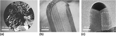
Here, we focus on growth twins in semiconductor crystals, examples of which are given in Fig. 1. It is well known Reference Fujiwara, Fukuda, Usami, Nakajima and Uda10–Reference Wagner18 that growth twins that intersect the crystal surfaces act as favorable attachment sites for the nucleation of new monoatomic layers of crystal. Twins are thought to be favorable attachment sites in comparison to facets where layers must overcome a large nucleation barrier for the formation of an isolated island, as first predicted by Gibbs. Reference Gibbs19 It is this difference in interfacial mobility, between twinned and faceted interfaces, that has dramatic consequences on the growth Reference Fujiwara, Fukuda, Usami, Nakajima and Uda10,Reference Fujiwara, Maeda, Usami and Nakajima11,Reference Gamalski, Voorhees, Ducati, Sharma and Hofmann12,Reference Shahani, Gulsoy, Poulsen, Xiao and Voorhees20 and coarsening Reference Shahani, Gulsoy, Roussochatzakis, Gibbs, Fife and Voorhees21,Reference Shahani, Xiao, Skinner, Peters and Voorhees22 morphologies of semiconductor crystals. What is much less understood is exactly how the growth twins enable the crystallization of new layers. Identifying the mechanisms of twin-mediated crystal growth remains an intense area of research.
Twinning across length scales: (a) heavily twinned Si wafer; (b) eutectic Si flake in an Al–Si alloy, in which the lines in the flake interior are twins Reference Lu and Hellawell23 ; (c) singly-twinned, Au-catalyzed Ge nanowire, where the boxed region corresponds to a single grain oriented along {111}. Reference Gamalski, Voorhees, Ducati, Sharma and Hofmann12 Reprinted with permissions from (b) Springer Reference Lu and Hellawell23 and (c) American Chemical Society. Reference Gamalski, Voorhees, Ducati, Sharma and Hofmann12

The paper is organized in three parts. The first summarizes the progress made in developing models for twin-mediated crystal growth, from the 1960s and onwards; the second presents four case studies that make use of state-of-the-art tools to experimentally validate these models; and the last suggests future developments needed for this field.
II. HISTORICAL DEVELOPMENT
A. Wagner–Hamilton–Seidensticker model
The first model for the growth of a twinned, diamond cubic (DC) crystal was proposed almost simultaneously by Hamilton and Seidensticker Reference Hamilton and Seidensticker13 and by Wagner Reference Wagner18 in 1960. We refer to the model as WHS theory. The central assumption in WHS theory is that the nucleation of new layers is initiated at the 141.1° concave basin, also known as the re-entrant groove, caused by the intersection of the Σ3 {111} twin plane with the {111}-bounded crystal surface. An atom adsorbed on the groove has four nearest neighbors, compared to three on a flat {111} plane Reference Ming and Sunagawa15–Reference Van de Waal17 and thus the groove may act as a preferential site for atom attachment. It is for this reason that the line energy, γ1 which reflects the number of broken bonds per unit length, is negative along the trijunction and thus the nucleation barrier is reduced. Reference Gamalski, Voorhees, Ducati, Sharma and Hofmann12,Reference Lee, Chung, Hwang and Kim24
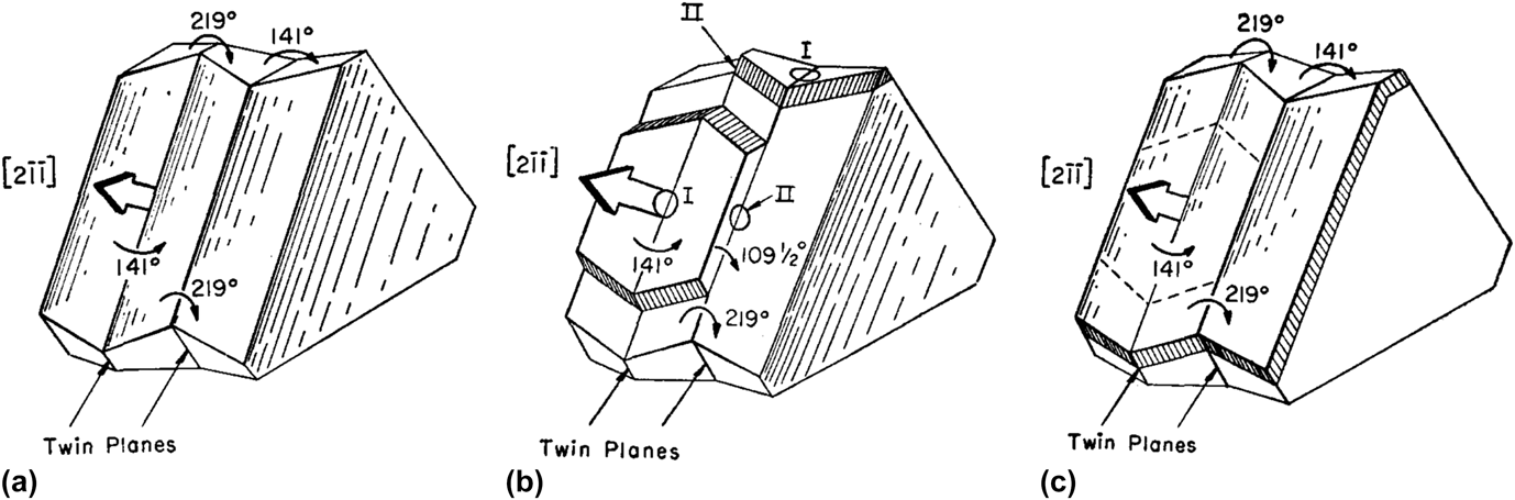
A crystal with one Σ3 twin boundary contains three such re-entrant grooves along the 〈211〉 directions [Fig. 2(a)]. Note that the geometry of the re-entrant groove sets the growth direction of the twinned interface. In general, and for a groove of angle α, Shahani and colleagues Reference Shahani, Gulsoy, Poulsen, Xiao and Voorhees20 showed that the growth direction 〈hkl〉 is 〈n11〉, where n is a function of α given by
 $$n = {{4 + 3\sqrt {2}\,\sin\, \alpha} \over {1 - 3\,\cos \,\alpha }}\quad .$$
(a) Crystal with a single Σ3 {111} twin plane. The twin plane emerges from the crystal in three re-entrant corners measuring 141.1°. Nucleation occurs readily at these corners, leading to rapid growth in the
 $\left[ {2\bar 1\bar 1} \right]$
,
 $\left[ {\bar 12\bar 1} \right]$
, and
 $\left[ {\bar 1\bar 12} \right]$
directions.
Reference Hamilton and Seidensticker13
(b) The trigonal solid that results if the three corner sites are allowed to grow. Note that the 141.1° re-entrant grooves have vanished. Reprinted with permission from American Institute of Physics.
Reference Hamilton and Seidensticker13

Thus for a = 141.1°, the growth direction is 〈211〉. For any given {111} Σ3 twin boundary, there are three 〈211〉 directions that satisfy the Weiss zone law Reference Kelly and Knowles25 (excluding inversion symmetry). In addition to the growth direction, both the line energy γ1 and nucleation barrier are sensitive to α; recently, Ref. Reference Gamalski, Voorhees, Ducati, Sharma and Hofmann12 proposed that γ1 and the nucleation barrier decrease monotonically with α. Consequently, the character of the twin boundary plays a dominant role in determining the growth behavior of the solid–liquid interfaces.
Since nucleation readily occurs at the re-entrant grooves compared to the {111} surfaces, the singly-twinned crystal grows rapidly at the re-entrant grooves and a trigonal solid with 60° corners is obtained, see Fig. 2(b). Rapid growth is eventually terminated owing to the disappearance of the re-entrant groove; thus, a multiply twinned interface is needed for steady-state crystal growth, and particularly in bulk systems. In other words, the solid is bounded by convex 218.9° ridge structures; since an adatom has only three nearest neighbors on either side of the ridge, Reference Ming and Sunagawa15–Reference Van de Waal17 the ridges are not capable of continuous propagation. On the other hand, singly-twinned nanocrystals are capable of steady-state growth, as will be explained in Sec. III. D.
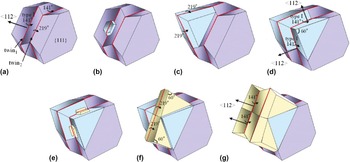
The WHS mechanism is given in Fig. 3. For a bulk crystal with two parallel twins [Fig. 3(a)], rapid growth occurs at the 141.1° re-entrant corner (referred to as a type I corner Reference Hamilton and Seidensticker13 ), similar to the crystal with one twin. When the nucleated layer propagates to the next twin, it forms a new re-entrant corner with an angle of 109.5° [referred to as a type II corner, Reference Hamilton and Seidensticker13 see Fig. 3(b)]. The type II corner is essential for the continuous propagation of the crystal because it relieves the shortage of nucleation sites caused by the formation of ridge structures. Growth occurs at the type II corner until the solid is back to its original shape [Fig. 3(c)]. This is the step–flow cycle that dictates growth in three of the possible 〈211〉 directions. The important feature of the WHS model is that the type I corner does not disappear during growth, since it is regenerated by activity at the type II corner. Reference Hamilton and Seidensticker13,Reference Wagner18 Thus, two twin boundaries are needed for steady-state growth. Wagner Reference Wagner18 applied this model to explain dendritic growth and branching in faceted crystals.
Idealized schematic of growth process of (a) crystal with two parallel twin planes, according to Wagner Reference Wagner18 and Hamilton and Seidensticker. Reference Hamilton and Seidensticker13 (b) Nucleation first occurs at the 141.1° re-entrant groove (type I). The initiated layer propagates to the second twin plane and forms a new corner measuring 109.5° (type II). (c) Nucleation then occurs at the type II corner, leading to the continuous propagation of the crystal in the 〈112〉 direction. While the broad {111} facets are shown to be stationary in (a–c), they do grow out, but at a much slower rate compared to the twinned interface. Reprinted with permission from American Institute of Physics. Reference Hamilton and Seidensticker13

B. Extensions to the WHS model
The WHS mechanism is capable of explaining DC crystal growth in 2D. Note that the
 $\left[ {2\bar 1\bar 1} \right]$
,
 $\left[ {\bar 12\bar 1} \right]$
, and
 $\left[ {\bar 1\bar 12} \right]$
growth directions in Fig. 3 are coplanar. This type of growth results in thin plates with well developed {111} side faces, see, e.g., Fig. 1(b). In 1996, van de Waal
Reference Van de Waal17
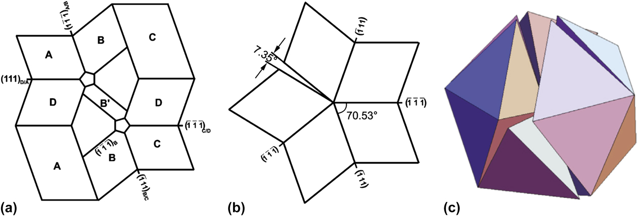
extended the WHS picture to explain isotropic 3D growth in FCC crystals. He introduced two new twin planes that are not parallel to the first set of twin planes in the WHS model. This is known in the literature as the “cross-twinning model” and is shown schematically in Fig. 4(a). Observe that the twin lamellae B and D are not parallel. As a result, the structure has re-entrant corners on all close-packed faces which will now stimulate growth in 3D.
Reference Van de Waal17
Schematic drawings of (a) cross-twinning model of FCC crystal growth, Reference Van de Waal17 wherein the twin lamellae B and D are non-parallel; (b) a fiveling, or 5-fold, cyclic twin with a 7.35° residual gap Reference Fregola and Scandale28 ; (c) construction of an icosahedron from 20 regular, twinned tetrahedra or four fivelings. Reference Kurtuldu, Jarry and Rappaz31 Reprinted with permissions from (a–b) Springer Reference Fregola and Scandale28 and (c) Elsevier. Reference Kurtuldu, Jarry and Rappaz31

Worth noting is that two lamellar twins [such as B and D in Fig. 4(a)] that are crossed form a region with local 5-fold symmetry. This is related to the frequent observation of multiply twinned particles (MTPs) with icosahedral or decahedral morphologies. Reference Hofmeister26,Reference Marks and Howie27 When considering the association of the {111} twin planes in cubic MTPs, they meet at a salient corner, forming a cyclic twin with a 7.35° residual gap [Fig. 4(b)]. Reference Hofmeister26,Reference Fregola and Scandale28 The twin components share a common 〈110〉 pseudo-five-fold axis at the particle core. As a result of the 7.35° angular deficiency, MTPs must contain defects or be intrinsically strained. Reference Hofmeister26,Reference Marks and Howie27 The energetics and stability of MTPs have been considered in Refs. Reference Marks29 and Reference Howie and Marks30. Figures 4(b)–(4c) show the construction of decahedral and icosahedral MTPs from 5 to 20 tetrahedra, Reference Fregola and Scandale28,Reference Kurtuldu, Jarry and Rappaz31 respectively.
Icosahedral MTPs should not to be confused with icosahedral quasicrystals (QCs). The latter are untwinned structures that are ordered but aperiodic. Reference Shechtman, Blech, Gratias and Cahn32 Early researchers Reference Pauling33 tried to explain QCs as interpenetrating polyhedra that meet at twin boundaries [see Fig. 4(c)]. However, it was later demonstrated Reference Janot34 that the diffraction patterns of icosahedral MTPs and icosahedral QCs can be distinguished without ambiguity.
C. Role of {100} interfaces during growth
Despite their popularity, the WHS mechanism and its cross-twinned version are not the only models for twin-mediated crystal growth. Over the past fifty years, several others Reference Ming and Sunagawa15,Reference Lee, Chung, Hwang and Kim24,Reference Jagannathan, Mehta, Timmons and Black35 have proposed alternative growth mechanisms involving {100} planes. That is, a portion of the solid–liquid interface has a {100} orientation. Here, we review these mechanisms and discuss their applicability and limitations.
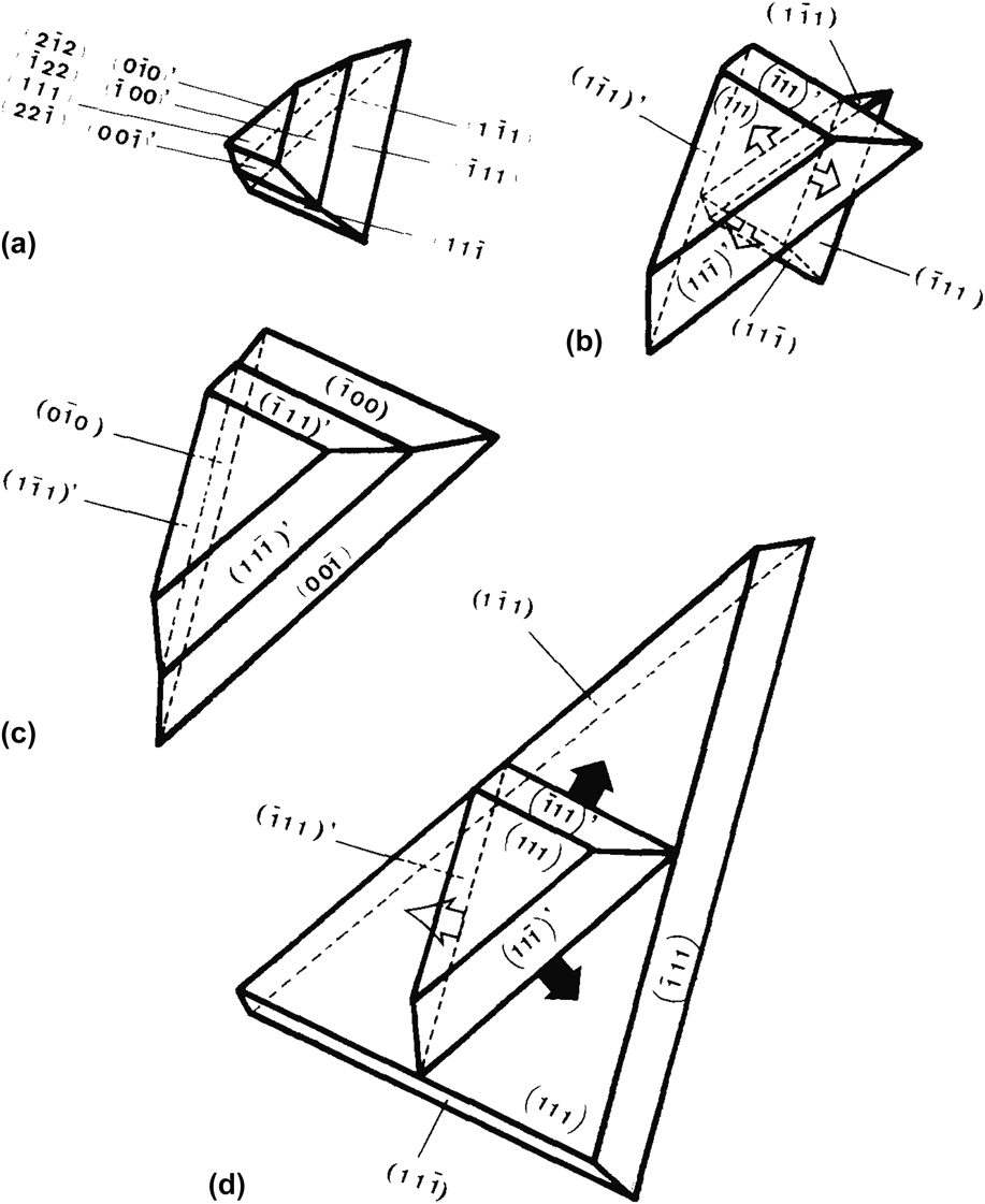
Ming and Sunagawa Reference Ming and Sunagawa15 were the first to postulate the growth process of a singly-twinned bicrystal, where one of the monocrystals is bounded by {111} and the other by {100}. For example, in Fig. 5(a), the upper crystal has three {100} interfaces while the lower crystal has three {111} interfaces. The twin plane is found between these two monocrystals. They assumed that the supersaturation is small enough to prevent 2D nucleation on the {111} interfaces, but large enough to allow growth on {100}. In this case, the {100} interfaces have a higher growth rate than the remaining surfaces and thus tend to grow out, forming a protrusion [Fig. 5(b)]. Then, three re-entrant grooves measuring 70.5° are produced at the junctions between the original, {111}-bounded monocrystal and the newly created, {111}-bounded monocrystal. Due to the enhanced nucleation at the re-entrant groove, the lower half of the bicrystal grows and the {100} interfaces appear again on the side faces of the lower monocrystal [Fig. 5(c)]. The cycle continues, whereby the {100} interfaces grow out and are replaced by {111} interfaces [Fig. 5(d)], and vice versa. The essential feature of the Ming and Sunagawa Reference Ming and Sunagawa15 mechanism is that cooperative and alternating growth occurs at the {111}/{111} re-entrant grooves and at the {100} interfaces. In this case, the groove angle α measures either 70.5° [Fig. 5(b)] or 109.5° [Fig. 5(d)].
Schematic illustration of the cooperation between {100} and {111} interfaces, according to Ming and Sunagawa. Reference Ming and Sunagawa15 (a) The upper half of the crystal (i.e., above the single twin) is bounded by three {100} surfaces while the lower half is bounded by {111}. (b) When the upper half of the crystal grows out, the three {100} surfaces disappear and three re-entrant corners measuring 70.5° are produced. Growth occurs at the re-entrant corners until (c) the {100} surfaces appear again on the faces of the lower half of the crystal. The {100} surfaces grow out, producing (d) re-entrant corners measuring 109.5°. Reprinted with permission from Elsevier. Reference Ming and Sunagawa15

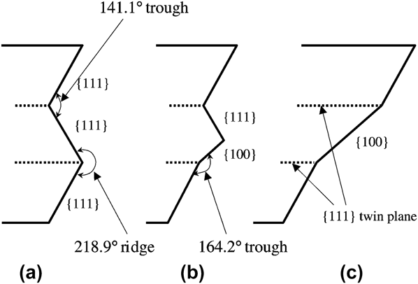
In a somewhat similar sense, Jagannathan et al. Reference Jagannathan, Mehta, Timmons and Black35 suggested an alternative growth mechanism of a doubly-twinned polycrystal with the initial configuration {111}/{111}/{111}, see Fig. 6(a). Layers accumulate at the 141.1° re-entrant groove, similar to the WHS mechanism. However, the edges (or “lips”) of the accumulated layers have the {100} orientation [Fig. 6(b)]. Note that the 164.2° {100}/{111} ridge structure is shallower than the 109.5° type II groove in the WHS model. Jagannathan et al. Reference Jagannathan, Mehta, Timmons and Black35 then hypothesized that the {100} face grows at a lower rate compared to the 141.1° {111}/{111} re-entrant groove such that the {100} face covers the middle crystal [Fig. 6(c)]; as such, this picture contradicts the proposed mechanism by Ming and Sunagawa. In this way, the re-entrant groove is not maintained and hence the interfacial morphology is not self-similar during growth.
Schematic of growth process of (a) crystal with two parallel twin planes, according to Jagannathan et al. Reference Jagannathan, Mehta, Timmons and Black35 Initially, the crystal surfaces have a {111}/{111}/{111} structure. (b) Layers accumulate at the 141.1° re-entrant groove, and their edges form a {100} lip in the middle crystal. The {100} face is assumed to grow at a lower rate than the {111}/{111} 141.1° re-entrant such that (c) the {100} face covers the middle crystal. Reprinted with permission from International Union of Crystallography. Reference Lee, Chung, Hwang and Kim24

More recently, Lee et al. Reference Lee, Chung, Hwang and Kim24 disagreed with Jagannathan's interpretation Reference Jagannathan, Mehta, Timmons and Black35 and modified Jagannathan's growth mechanism of a doubly-twinned polycrystal as follows: instead of the {100} lip enveloping the middle crystal, growth on the {100} lip occurs simultaneously with growth at the re-entrant groove, see Fig. 7. That is, 2D nucleation on the {100} interface is necessary to prevent the {111}/{111} re-entrant groove from disappearing (i.e., outgrowing itself). Note that the cooperation between {100} interfaces and re-entrant grooves was already suggested by Ming and Sunagawa. Reference Ming and Sunagawa15 However, their idea (Fig. 5) shows the appearance and disappearance of the 70.5° and 109.5° re-entrant grooves, whereas in the mechanism proposed by Lee et al. (Fig. 7), the 141.1° re-entrant groove is maintained during the growth process. During steady-state growth, then, the interfacial configuration according to Lee et al. Reference Lee, Chung, Hwang and Kim24 is of the type {111}/{111}/{100}/{111}.
Schematic of growth process of a crystal with two parallel twin planes, according to Lee et al. Reference Lee, Chung, Hwang and Kim24 (a) Nucleation first occurs at the 141.1° re-entrant groove [see Fig. 3(b)]. (b) The nucleated layers accumulate, forming {100} edges [see Fig. 6(b)]. (c) 2D nucleation occurs on the {100} lip as well as on the re-entrant groove. During steady-state growth, the crystal surfaces have a {111}/{111}/{100}/{111} structure. Reprinted with permission from International Union of Crystallography. Reference Lee, Chung, Hwang and Kim24

A significant assumption in the work by Lee et al. Reference Lee, Chung, Hwang and Kim24 is that the {100} interfaces grow via 2D nucleation [as shown schematically in Fig. 7(c)], wherein the interfacial velocity of {100} varies exponentially with driving force. However, for semiconductor crystals, the {100} interface is well known to be atomically rough. For instance, the Jackson α factor for Si{100} is 1.8. Reference Jackson36 Therefore, there should be many kink sites along the {100} interface such that 2D nucleation is not necessary to facilitate the growth of new layers. For this reason, the rough {100} interfaces should not have been drawn as facets in Figs. 5–7. Indeed, Beatty and Jackson Reference Beatty and Jackson37 demonstrated via Monte Carlo simulation that the Si{100} interfacial velocity varies linearly with driving force, consistent with the Wilson–Frenkel growth law. Reference Jackson36,Reference Ratke and Voorhees38 Under weak supersaturation, then, the velocity of a {111} facet plane growing via 2D nucleation is much smaller than the velocity of a rough {100} plane. Thus, it is more likely that the {100} habit plane would eventually grow out, leaving the crystal bounded by {111}. This statement is consistent with the first part of the Ming and Sunagawa mechanism [Figs. 5(a)–5(b)], but it is unclear why the rough interfaces reappear during the proposed growth sequence [Figs. 5(c)–5(d)]. Instead, it is anticipated that the solid is fully bounded by {111} planes during steady-state growth, as in the WHS mechanism.
A second complication in the analyses of both Jagannathan Reference Jagannathan, Mehta, Timmons and Black35 and Lee et al. Reference Lee, Chung, Hwang and Kim24 concerns the line energy of the type II groove. Both sets of authors view the layer advance across the 109.5° (type II) groove as energetically unfavorable, compared to nucleation at the 141.1° (type I) re-entrant groove. For this reason, they propose alternative mechanisms involving the rough {100} interface. However, as pointed out by van de Waal, Reference Van de Waal16 there is no reason for an atom to prefer the type I groove over the type II groove because both sites have a coordination number of four (albeit different geometries). The situation may be different in an ionic crystal in which the type I and type II sites are electrostatically inequivalent. In this case, the anisotropic electrostatic interactions should be taken into account. Reference Van de Waal16 In particular, the growth process of ionic crystals, e.g., silver halide (AgX where X = Cl, Br, and I), has been described in Refs. Reference Bögels, Buijnsters, Verhaeren, Meekes, Bennema and Bollen39–Reference Jagannathan, Chen, Mehta and Jagannathan42.
III. RECENT RESULTS
The above models of twin-mediated growth crystal have remained unverified until the 21st century. Advances in the dynamic imaging of microstructure via lattice-resolved transmission electron microscopy (TEM), Reference Gamalski, Voorhees, Ducati, Sharma and Hofmann12 confocal scanning laser microscopy, Reference Fujiwara, Obinata, Ujihara, Usami, Sazaki and Nakajima43 x-ray tomography (XRT), Reference Shahani, Gulsoy, Poulsen, Xiao and Voorhees20 and x-ray topography Reference Reinhart, Buffet, Nyugen-Thi, Billia, Jung, Mangelinck-Nöel, Bergeon, Schenk, Härtwig and Baruchel44,Reference Tandjaoui, Mangelinck-Nöel, Reinhart, Furtera, Billia, Lafford, Baruchel and Guichard45 have finally enabled researchers to identify the growth mode of twinned interfaces. Below we present four case studies where realtime imaging is used to investigate twinning phenomena.
A. Growth of Si-faceted dendrites
To solve the puzzle of twin-mediated crystal growth, Fujiwara and coworkers Reference Fujiwara, Fukuda, Usami, Nakajima and Uda10,Reference Fujiwara, Maeda, Usami and Nakajima11,Reference Yang, Fujiwara, Gotoh, Maeda, Nozawa, Koizumi and Uda46,Reference Yang, Fujiwara, Maeda, Nozawa, Koizumi and Uda47 developed a 2D in situ observation system to watch the growth of faceted Si dendrites. Based on their experimental data, they presented a growth mechanism (hereafter referred to as the F model) of a doubly-twinned interface that is markedly different from any of the above models. The F mechanism is given in Fig. 8. In their approach, triangular 60° corners (at the length-scale of the crystal) form at the growth tip, and the direction of the 60° corners changes during growth; this is made possible by the alternate formation and disappearance of type I corners at each of the two twin planes, in contrast to the WHS mechanism. In particular, the triangular corner centered on twin1 is colored blue [Fig. 8(c)], and the triangular corner centered on twin2 is colored yellow [Fig. 8(f)]. Thus, according to the F model, type II corners play no role during the growth process. Reference Fujiwara, Fukuda, Usami, Nakajima and Uda10,Reference Fujiwara, Maeda, Usami and Nakajima11
Schematic of growth process of (a) crystal with two parallel twin planes (in red), according to Fujiwara et al. Reference Fujiwara, Maeda, Usami and Nakajima11 (b) Nucleation first occurs at the type I re-entrant groove [see Fig. 3(b)], where twin1 intersects the crystal surface. (c) A triangular corner measuring 60° at the tip is formed due to the rapid growth at the re-entrant groove. (d) The triangular corner propagates across twin2, leading to the formation of two new type I grooves centered on twin2. (e–g) Rapid growth occurs at the new type I corners, thereby regenerating the type I corners at twin1. This process from (a) through (g) occurs continuously such that the net growth direction is 〈112〉 (see Fig. 3). Reprinted with permission from American Physical Society. Reference Fujiwara, Maeda, Usami and Nakajima11

Based on calculations of the time consumed in each stage of the F mechanism and the growth length in one cycle [(Figs. 8(a)–8(g)], Fujiwara et al. were able to derive the growth velocity along 〈112〉,
 ${V_{\left\langle {112} \right\rangle }}$
, as
 $${V_{\left\langle {112} \right\rangle }} = {\textstyle{h \over {2\left( {{h \mathord{\left/ {\vphantom {h {{V_{{\rm{twin}}}}}}} \right. \kern-\nulldelimiterspace} {{V_{{\rm{twin}}}}}}\; + \;{d \mathord{\left/ {\vphantom {d {{V_{{\rm{twin}}}}}}} \right. \kern-\nulldelimiterspace} {{V_{{\rm{\{111}\}}}}}}} \right)}}}}+{V_{\{111{}\}}$$
where h is the height of the triangular corner, d is the twin spacing,
 ${V_{{\rm{twin}}}}$
is the twin growth velocity, and
 ${V_{\{ 111\} }}$
is the {111} surface growth velocity. Equation (2) was derived based on geometrical arguments only, and h,
 ${V_{{\rm{twin}}}}$
, and
 ${V_{\{ 111\} }}$
are assumed to be constants at a given undercooling.
Reference Yang, Fujiwara, Gotoh, Maeda, Nozawa, Koizumi and Uda46
A similar expression was proposed for faceted dendritic growth in the 〈110〉 direction.
Reference Yang, Fujiwara, Gotoh, Maeda, Nozawa, Koizumi and Uda46
Thus the 〈112〉 dendrite growth velocity is inversely related to the twin spacing d. Consider the asymptotic behavior: in the limit as d → ∞,
 ${V_{\left\langle {112} \right\rangle }}$
is given by
 ${V_{\{ 111\} }}$
as the crystal is bounded entirely by {111} facet planes, i.e., twins are nowhere to be found. In the other extreme, as d → 0, the growth velocity exceeds
 ${V_{\{ 111\} }}$
by an amount
 ${V_{{\rm{twin}}}}/2$
, where the factor of two is due to the fact that two triangular corners must grow in a single cycle of the F mechanism.
Reference Yang, Fujiwara, Gotoh, Maeda, Nozawa, Koizumi and Uda46
Interestingly, in the limit of very low velocity of the {111} plane, the velocity of the crystal in the 〈112〉 direction is independent of the twin growth velocity. Thus, a nonzero {111} facet growth velocity is essential in their model. These results have been verified by tracking in situ the growth velocities of three dendrites as a function of their twin spacing.
Reference Yang, Fujiwara, Gotoh, Maeda, Nozawa, Koizumi and Uda46
In addition, provided that the dependencies of
 ${V_{\{ 111\} }}$
and
 ${V_{{\rm{twin}}}}$
on undercooling ΔT are known, Eq. (2) can be re-expressed in terms of ΔT, as has been done in Ref. Reference Yang, Fujiwara, Maeda, Nozawa, Koizumi and Uda47.
More recently, Fujiwara et al.
Reference Fujiwara, Tokairin, Pan, Koizumi, Nozawa and Uda48
have demonstrated that morphological instabilities are amplified at twin boundaries in Si. It was shown experimentally that in a pure material, the instability occurs even in a positive temperature gradient, meaning that the classical Mullins and Sekerka criterion
Reference Mullins and Sekerka49,Reference Mullins and Sekerka50
cannot be applied for defective crystals. In explaining this behavior, Fujiwara et al.
Reference Fujiwara, Tokairin, Pan, Koizumi, Nozawa and Uda48
assumed that the interfacial velocity
 $V$
is expressed as
 $V \approx K\Delta T,$
where K is the kinetic coefficient, and ΔT is the undercooling. Thus, when the condition
 ${{{K_{\rm{t}}}\Delta {T_{\rm{t}}}} \mathord{\left/ {\vphantom {{{K_{\rm{t}}}\Delta {T_{\rm{t}}}} {{K_{\rm{b}}}\Delta {T_{\rm{b}}} > 1}}} \right. \kern-\nulldelimiterspace} {{K_{\rm{b}}}\Delta {T_{\rm{b}}} > 1}}$
is satisfied, where the subscripts indicate the top (t) and bottom (b) of the perturbation, the morphological instability occurs at the twin boundaries.
Reference Fujiwara, Tokairin, Pan, Koizumi, Nozawa and Uda48
It is clear that the values of the kinetic coefficients are critical, since in a positive temperature gradient
 $\Delta {T_{\rm{b}}} > \Delta {T_{\rm{t}}}$
. In this case, the wave length of the perturbation is given by the spacing between the parallel twins. Thus, the values of the kinetic coefficients
 ${K_{\rm{t}}}$
and
 ${K_{\rm{b}}}$
need to be clarified to further develop the theory of instability in the presence of defects.
B. Growth of Si particles in Al–Si–Cu liquid
While the F model satisfactorily explains the results of Fujiwara et al. Reference Fujiwara, Fukuda, Usami, Nakajima and Uda10,Reference Fujiwara, Maeda, Usami and Nakajima11 , it is not immediately clear how the experimental conditions (e.g., temperature and undercooling) influence the morphology of the twinned interface. Furthermore, the studies conducted by Fujiwara et al. are limited to examining 2D images of the propagating growth front. However, microstructure develops in 3D, and therefore time-resolved, 3D measurements can yield new insights into the twin-mediated growth process. Such an approach would allow us to quantify unambiguously the dynamics of crystal growth.
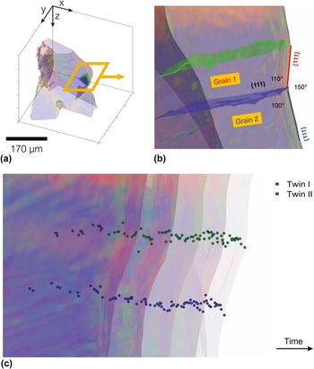
To this end, Shahani et al. Reference Shahani, Gulsoy, Poulsen, Xiao and Voorhees20 have visualized the growth process of Si particles in an Al–Si–Cu liquid via synchrotron-based x-ray tomography. Using their 4D (i.e., 3D space and time-resolved) data, they were able to follow the dynamics of lamellar grain boundaries within the Si particles, see Fig. 9. The interested reader should consult Ref. Reference Shahani, Gulsoy, Poulsen, Xiao and Voorhees20 for computational details. Assuming that the crease in the solid–liquid interface corresponds to an internal grain boundary, the path of the crease in time gives the location of the grain boundary within the microstructure. After computing the angles between the grain boundaries and the habit planes, and the angle between the two habit planes themselves, Shahani et al. Reference Shahani, Gulsoy, Poulsen, Xiao and Voorhees20 found that the lamellar boundaries must be Σ3 {111} coherent (twin) boundaries, see Figs. 9(a)–9(b). The propagation of this doubly-twinned interface is shown in Fig. 9(c), together with the internal twin boundaries. It can be seen that the re-entrant groove, i.e., where the blue boundary meets the crystal surface, does not disappear during the growth process. This picture is consistent with the WHS mechanism, and inconsistent with the F mechanism. Reference Shahani, Gulsoy, Poulsen, Xiao and Voorhees20
Characterization of grain boundaries via 4D (i.e., space and time-resolved) x-ray tomography data. Reference Shahani, Gulsoy, Poulsen, Xiao and Voorhees20 (a) Semi-transparent Si particle overlaid with surfaces of the grain boundaries. (b) Magnified view of the boxed region in (a). The angular relationships are consistent with {111} Σ3 (twin) boundaries. (c) Propagation of the doubly-twinned interface in (b) during growth. Five semi-transparent isochromes are plotted 600 s apart, together with points along the two twin boundaries (labeled I and II and colored in blue and green, respectively). The morphology of the twinned interface appears identical between time-steps, suggesting that the WHS mechanism is operant. Reprinted with permission from Nature Publishing Group. Reference Shahani, Gulsoy, Poulsen, Xiao and Voorhees20

Shahani et al.
Reference Shahani, Gulsoy, Poulsen, Xiao and Voorhees20
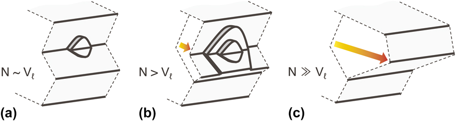
rationalized the above by noting that the morphology of the twinned interface results from an interplay between the nucleation rate
 $\dot N$
at the re-entrant groove and the lateral growth rate V
l of the layers so initiated. Consider the following three regimes illustrated in Fig. 10: (a)
 $\dot N \sim {V_{\rm{l}}}$
, (b)
 $\dot N > {V_{\rm{l}}}$
, and (c)
 $\dot N \gg {V_{\rm{l}}}$
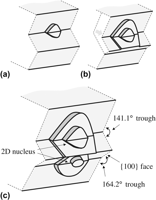
. Case (a) resembles the “birth and spread” of layers encountered in the WHS mechanism (Sec. II. A), whereas case (c) suggests that the re-entrant accumulates a multitude of layers that are stacked one above the other. At the macroscale, this configuration may have the appearance of a triangular mound projecting into the melt [see Figs. 8(c) and 8(f)]. Thus, the F mechanism may be thought to operate at higher
 $\dot N$
than the WHS mechanism (relative to V
l). In general, the growth mechanism of a doubly-twinned interface is specific to the kinetics of the system so investigated.
Morphology of the twinned interface under different growth conditions: (a) nucleation rate
 $\dot N$
at the re-entrant groove is the same order of magnitude as lateral growth rate V
l of layers so initiated, (b)
 $\dot N > {V_{\rm{l}}}$
, and (c)
 $\dot N \gg {V_{\rm{l}}}$
. A continuum of twinned growth morphologies is attainable.
C. Directional growth of polycrystalline Si
The genesis of twin defects is a topic much less studied than their growth promoting effects. By analyzing the driving forces for defect formation, we can achieve a more precise control of microstructure during processing. Currently, there are two schools of thought regarding the formation of growth twins: the first is that the critical nucleus is itself twinned, Reference Senechal51,Reference Wang, Lu and Hogan52 while the second is that twins arise naturally due to errors in the stacking of {111} planes during growth. Reference Fujiwara, Maeda, Usami, Sazaki, Nose and Nakajima53,Reference Gleiter, Cahn and Haasen54 The latter is often referred to as the “growth accident hypothesis.” Thus, do twins form during nucleation or growth?
To shed light on the formation of twin defects, Mangelinck-Nöel and colleagues Reference Tandjaoui, Mangelinck-Nöel, Reinhart, Furtera, Billia, Lafford, Baruchel and Guichard45,Reference Tandjaoui, Mangelinck-Nöel, Reinhart, Billia and Guichard55,Reference Riberi-Béridot, Mangelinck-Nöel, Tandjaoui, Reinhart, Billia, Lafford, Baruchel and Barrallier56,Reference Tsoutsouva, Riberi-Béridot, Regula, Reinhart, Baruchel, Guittonneau, Barrallier and Mangelinck-Nöel57 have made use of two in situ x-ray imaging techniques: radiography (i.e., projection microscopy) and topography (i.e., diffraction imaging) during the directional solidification of polycrystalline Si. The x-ray radiography images were collected in the density contrast mode. Because the density of solid Si (2.31 g/cm3) and liquid Si (2.56 g/cm3) are very close, Mangelinck–Nöel and colleagues needed to apply image processing methods to clearly resolve the solid–liquid interfaces, see Ref. Reference Tandjaoui, Mangelinck-Nöel, Reinhart, Furtera, Billia, Lafford, Baruchel and Guichard45 for further details. Simultaneously, x-ray topographs (also known as diffraction spots) were collected in the transmission mode; they contain information on the shape and deformation of individual grains of the solid phase.
An example of their multimodal approach is given in Fig. 11. Reference Riberi-Béridot, Mangelinck-Nöel, Tandjaoui, Reinhart, Billia, Lafford, Baruchel and Barrallier56 The upper part of the topographs [Figs. 11(d)–11(g)] corresponds to the solid–liquid interface [Fig. 11(b)]. The striped appearance of the topographs indicates repeated twinning events; in addition, the triangular shape in Fig. 11(g) reveals that the twins nucleate on the right side of the sample. This can be explained by noting that it is energetically favored for new grains to nucleate at the trijunction where the solid, liquid, and crucible walls meet. Reference Riberi-Béridot, Mangelinck-Nöel, Tandjaoui, Reinhart, Billia, Lafford, Baruchel and Barrallier56 In general, twinning is thought to occur preferentially at the solid–solid–liquid triple line, Reference Tandjaoui, Mangelinck-Nöel, Reinhart, Billia and Guichard55,Reference Duffar and Nadri58 where a grain boundary meets the crystal surface, at the solid–liquid–crucible triple line, Reference Riberi-Béridot, Mangelinck-Nöel, Tandjaoui, Reinhart, Billia, Lafford, Baruchel and Barrallier56 as shown here, and at the solid–liquid–vapor triple line, Reference Voronkov59,Reference Hurle60 in the case of Czochralski growth.
(a) Optical microscope image of a directionally solidified Si sample; for the experimental conditions, see Ref. Reference Riberi-Béridot, Mangelinck-Nöel, Tandjaoui, Reinhart, Billia, Lafford, Baruchel and Barrallier56. (b) X-ray projection showing the solid–liquid interface during the growth process. The magnified image shows the presence of a grain boundary groove (outlined in black). (c) Laue diagram recorded in transmission mode at 1246 s after the onset of solidification. X-ray topographs of the circled
 $\left( {\bar 1\bar 12} \right)$
reflection at times (d) 180, (e) 420, (f) 900, and (g) 1246 s. Reprinted with permission from Elsevier.
Reference Riberi-Béridot, Mangelinck-Nöel, Tandjaoui, Reinhart, Billia, Lafford, Baruchel and Barrallier56

To confirm the identity of the twin defects, Mangelinck-Nöel and colleagues have performed electron backscatter diffraction (EBSD) scans of their as-solidified samples. Reference Riberi-Béridot, Mangelinck-Nöel, Tandjaoui, Reinhart, Billia, Lafford, Baruchel and Barrallier56,Reference Tsoutsouva, Riberi-Béridot, Regula, Reinhart, Baruchel, Guittonneau, Barrallier and Mangelinck-Nöel57 They have found that the population of Σ3 boundaries dominate at more than 75% in the entire sample, while Σ9 and Σ27 boundaries do not exceed 5 and 6% respectively. Reference Riberi-Béridot, Mangelinck-Nöel, Tandjaoui, Reinhart, Billia, Lafford, Baruchel and Barrallier56 They note that the higher order coincident site lattices (CSLs) form due to the encounter between multiple Σ3 twins. Reference Riberi-Béridot, Mangelinck-Nöel, Tandjaoui, Reinhart, Billia, Lafford, Baruchel and Barrallier56 Thus, the following “rule” applies, given by Randle, Reference Randle61 concerning the joining or dissociation of CSLs:
 $$\Sigma A + \Sigma B \to \Sigma \left( {A \times B} \right)$$
 $$\Sigma A + \Sigma B \to \Sigma \left( {{A \mathord{\left/ {\vphantom {A B}} \right. \kern-\nulldelimiterspace} B}} \right)$$
where the second relationship applies if A/B is an integer and A > B. Reference Randle61 Furthermore, their results are in qualitative agreement with the five parameter grain boundary characterization of Rohrer et al. Reference Ratanaphan, Yoon and Rohrer62 The latter team has found that Σ3 boundaries make up the largest fraction of all grain boundaries at 29.6% (percentage by number). Reference Ratanaphan, Yoon and Rohrer62 Any quantitative differences in the grain boundary populations may be due to differences in the solidification pathways of the Si samples.
EBSD is also capable of measuring the difference between the orientation of a point in the grain and the grain average orientation, also known as a grain orientation spread (GOS) map. Reference Tsoutsouva, Riberi-Béridot, Regula, Reinhart, Baruchel, Guittonneau, Barrallier and Mangelinck-Nöel57 This indicates the deformation field within the grain. By using this approach, Mangelinck-Nöel and colleagues noticed that twinned grains are less distorted in comparison to the seed crystal. Reference Tsoutsouva, Riberi-Béridot, Regula, Reinhart, Baruchel, Guittonneau, Barrallier and Mangelinck-Nöel57 Further support is provided by x-ray topography, in which deformations are evidenced by highly distorted diffraction spots. Reference Riberi-Béridot, Mangelinck-Nöel, Tandjaoui, Reinhart, Billia, Lafford, Baruchel and Barrallier56 Altogether, this suggests that twinning may relax the stresses in the growing structure. Reference Riberi-Béridot, Mangelinck-Nöel, Tandjaoui, Reinhart, Billia, Lafford, Baruchel and Barrallier56,Reference Tsoutsouva, Riberi-Béridot, Regula, Reinhart, Baruchel, Guittonneau, Barrallier and Mangelinck-Nöel57
D. Growth of Au-catalyzed Ge nanowires
The situation is markedly different in nanoscale systems, in which steady-state growth is possible at a single twin boundary. Recently, Gamalski et al. Reference Gamalski, Voorhees, Ducati, Sharma and Hofmann12 investigated the growth process of an Au-catalyzed, singly-twinned Ge nanowire (NW) via lattice-resolved TEM. Figure 1(c) shows a representative image of a Ge NW during the growth process with a liquid AuGe alloy at its tip (in black). The twin boundary is located at the center of the NW. The Ge NW exhibits a “V-shaped,” convex interface with the liquid AuGe catalyst; this geometry is consistent with the re-entrant groove. Reference Gamalski, Voorhees, Ducati, Sharma and Hofmann12
Unlike bulk systems, the liquid catalyst–NW interface is nonplanar, but truncated toward the triple phase boundary (TPB) where the liquid catalyst, solid NW, and gas atmosphere meet. Gamalski et al. observed that the interface near the TPB is highly mobile and requires little supersaturation to move. Hence, the NW grows at a rate completely determined by the nucleation rate at the single twin, and the growth process is stable. Reference Gamalski, Voorhees, Ducati, Sharma and Hofmann12 This single twin configuration is not unique to Ge nanowires but has been observed in ZnO nanowires, Reference Dai, Zhang, Bai and Wang63 InSb nanosails, Reference de la Mata, Leturcq, Plissard, Rolland, Magén, Arbiol and Caroff64 and InAs nanoleaves. Reference Soo, Zheng, Gao, Tan, Jagadish and Zou65
IV. CONCLUSIONS AND OUTLOOK
Since the discovery of the transistor, considerable efforts have been devoted to developing models for twin-mediated crystal growth and the experimental evidence to support them. While the classical WHS approach is the most widely accepted growth model in the literature, it does not necessarily operate in ionic and nanoscale crystals. Furthermore, the WHS mechanism does not explain the 3D growth of MTPs, nor the formation of triangular corners. Thus, the growth process of twinned crystals is in some cases more complex than originally predicted by Wagner, Reference Wagner18 Hamilton, and Seidensticker. Reference Hamilton and Seidensticker13 Even so, we have a much better understanding of the rich variety of growth morphologies attainable than we did fifty years ago.
So what of the future? We need to turn our attention to the thermophysical factors governing the distribution of defects in growing crystals. For example, what sets the spacing between the twin defects I and II in Fig. 9? If the “growth accident hypothesis” is appropriate, then one might suppose that twinning is a purely stochastic event. However, and as discussed above, twinning occurs most frequently at the trijunctions and edges of the sample. Thus, the formation of twins may be considered a deterministic process. Further research is needed to elucidate the mechanisms for twin nucleation. Secondly, how does the chemical environment, e.g., in multicomponent alloys, influence the frequency of twinning? For instance, it is well known that C, Na, and Sr (among other impurities) induce twinning in Si; this is referred to in the literature as the “impurity induced twinning” hypothesis, see, e.g., Refs. Reference Lu and Hellawell23, and Reference Ravi66–Reference Li, Hage, Wiessner, Romaner, Scheiber, Sartory, Ramasse and Schumacher68. However, it is unclear at this stage why certain elements and intermetallic compounds promote twinning while others do not. A complete theory of modification has yet to be developed.
To answer the above questions, we must harness the new capabilities in both in situ imaging and ex situ characterization methods, as already suggested in Sec. III. Beyond those state-of-the-art techniques listed, we note that liquid cell TEM has gained traction in the biomaterials community as it permits the direct observation of sub-critical nuclei in solution. Reference Nielsen, Li, Zhang, Aloni, Han, Frandsen, Seto, Banfield, Cölfen and De Yoreo69 In terms of ex situ methods, the plasma focused ion beam (PFIB) offers material removal rates 60 greater than that of conventional FIB systems, thereby extending our capability for 3D EBSD of samples that are hundreds of micrometers in dimension. Reference Burnett, Kelley, Winiarski, Contreras, Daly, Gholinia, Burke and Withers70 3D EBSD is also possible using laser-based material removal approaches and an SEM, Reference Echlin, Mottura, Torbet and Pollock71,Reference Echlin, Titus, Kraemer and Pollock72 or automated SEM-mechanical polishing approaches, Reference Rowenhorst, Gupta, Feng and Spanos73,Reference Uchic, Ghosh and Dimiduk74 but on larger length-scales than the PFIB. This method would enable researchers to visualize and quantify the grain boundary networks present in their as-solidified samples. We anticipate that the integration of multiple imaging techniques, such as those mentioned in this paper, will help pinpoint exactly when and where the twin defects form in semiconductor crystals.