1. Introduction
Soft robots fundamentally differ from traditional rigid robots, which use hard metallic or plastic exteriors. Instead, the core components of soft robots, such as structural, actuation, and sensing elements, are generally made of soft, deformable materials. These materials have a Young’s modulus ranging from 104 to 109 Pa [Reference Rus and Tolley1], providing soft robots with intrinsic compliance, enhanced safety, and a theoretically infinite number of degrees of freedom [Reference Cheney, Bongard and Lipson2]. These characteristics give soft robots distinct advantages over traditional rigid robots in fields such as environmental adaptability [Reference Yang, Wu, Li, Yang and Chen3, Reference Yang, Li and Chen4], biocompatibility [Reference Cianchetti, Laschi, Menciassi and Dario5, Reference Coyle, Majidi, LeDuc and Hsia6], structural flexibility [Reference Rieffel and Mouret7], and safety in human–robot interaction [Reference Ohta, Valle, King, Low, Yi, Atkeson and Park8–Reference Kim, Yoon and Park10]. Consequently, soft robots have been widely used in fields such as rehabilitation [Reference Peng and Huang11–Reference Wang, Peng, Yao, Biggar, Hu, Yin and Fan13], disaster rescue [Reference Wang, Zhang, Shen and Chen14–Reference Samm, Durairajah and Gobee16], industrial manufacturing [Reference El-Atab, Mishra, Al-Modaf, Joharji, Alsharif, Alamoudi, Diaz, Qaiser and Hussain17], and biomedical applications [Reference Moghadam, Kouzani, Torabi, Kaynak and Shahinpoor18–21].
Soft robots rely on distinct actuation mechanisms. Due to the flexibility of material, traditional motor-driven approaches are generally unsuitable [Reference Gao22], necessitating the development of actuators specifically designed for soft structures. Currently, common actuation methods for soft robots include fluid pressure actuation, cable-driven actuation, and deformation of smart materials [Reference Li, Hu and Yang23].
Due to its inherent advantages, fluid-driven actuation has been widely utilized in soft robots since their early development stages [Reference Polygerinos, Correll, Morin, Mosadegh, Onal, Petersen, Cianchetti, Tolley and Shepherd24, Reference McDonald and Ranzani25]. Compared to other actuation methods, fluid-driven actuation is particularly well-suited to the structural characteristics of soft robots, utilizing fluid media such as air or liquid. This approach leverages the highly dynamic and continuous deformations of soft materials, enabling complex movements and biomimetic behaviors without the need for intricate mechanical linkages or rigid components [Reference Sun, Chen, Bian and Zhao26, Reference Li, Wang, Foo, Godaba, Zhu and Yap27].
However, maximizing the potential of fluid-driven actuation in soft robots critically depends on achieving precise fluid regulation. Effective fluid regulation impacts not only key performance metrics, such as speed [Reference Xu, Nunez, Souri and Wood28], force [Reference Cai, Wang, Tian, Xu and Zhang29], and precision [Reference Xavier, Fleming and Yong30], but also the operational efficiency and adaptability of soft robots in diverse environments.
In soft robots, fluid regulation primarily depends on the coordinated interaction of pressure sources, valves, and the fluid medium. The pressure source provides the necessary driving force for the movement of soft robots, thereby determining their fundamental actuation capability. The fluid, acting as the medium, deforms the soft structure through the effects of flow and pressure. Smart fluids can respond to external stimuli, such as electric or magnetic fields, to reversibly adjust their flow properties (mainly viscosity), enabling precise regulation of fluid behavior in soft robots. Valves act as the central link between the pressure source and the fluid medium, playing a critical role in fluid regulation. The flow rate, volume, and direction of the fluid are controlled by valves, directly influencing how the soft robot deforms and performs according to task requirements. These three components – pressure source, valve, and smart fluid – are essential for the effective regulation of fluid in soft robots. Based on their roles, fluid regulation strategies in soft robots can be generally classified into three main categories: valve-based, smart fluid-based, and pressure source-based strategies.
Valves are the ``gatekeepers” of fluid regulation systems and serve as the central link between the pressure source and the fluid medium, making them the core components in fluid regulation. Valves determine the flow rate, volume, and direction of the fluid, directly influencing how the soft robot deforms and performs according to task requirements. The design of valves allows soft robots to rapidly and accurately change the flow path or toggle between flow and blockage, enabling quick and effective regulation of fluid dynamics. Compared to other components in the fluid regulation system, the pressure source provides the energy required to drive fluid movement but lacks the flexibility and precision needed to adjust fluid flow. For tasks that require rapid regulation of flow rate and speed, precise valve design becomes essential. While smart fluids can alter their flow characteristics in response to external fields, their control precision, flexibility, and adaptability to environmental changes are limited. Valves, on the other hand, compensate for these limitations by providing precise control over fluid switching, flow paths, and speed through structural changes, enabling higher precision in fluid regulation. Unlike smart fluids, which rely on external fields for adjustment, valve regulation fluid flow with physical structures, offering more accurate control and faster response times. The unique advantages of valve design include its simplicity and precision. Valves can achieve complex fluid regulation through simple mechanical movements or material deformation, whereas pressure source-based and smart fluid-based systems often require additional external devices, such as equipment to generate magnetic or electric fields. Furthermore, valves provide a level of control that is unmatched by pressure sources or smart fluids, enabling more efficient, flexible, and precise fluid regulation.
Currently, there are numerous reviews on fluid regulation strategies in soft robots. The review investigated by McDonald et al. [Reference McDonald and Ranzani25] provides a comprehensive overview of on-board fluid control hardware methods in fluidic soft robots, with a particular emphasis on innovative valve designs. It also proposes several evaluation criteria for comparing the merits of different control approaches. Han et al. [Reference Han, Li, Xiong, He, Zhao and Chen31] provide a comprehensive review of soft valves used in soft robots, examining them from both structural and material perspectives, and also present the current modeling strategies for soft robots. In addition, many reviews have explored actuation methods and pressure sources in soft robots [Reference Nakamura32–Reference Tang, Li, Ma, Yang, Luo, Wang and Jiang34].
While these reviews offer valuable insights into fluid regulation in soft robots, a comprehensive overview and detailed classification of fluid regulation strategies, particularly focusing on valve innovations, remains lacking. This review aims to fill this gap by conducting an extensive investigation into the fluid regulation strategies employed in soft robots, accompanied by a detailed classification, as depicted in Figure 1. Each category is further subdivided based on its distinct control principles and the role each component plays in fluid regulation.
Classification of fluid regulation strategies in soft robots.

In this review, a comprehensive survey is conducted to summarize the fluid regulation strategies used in soft robots, followed by an analysis and comparison of the effectiveness of different fluid regulation strategies. Finally, the future development trends of fluid regulation strategies in soft robots are discussed.
2. Fluid regulation strategies based on valves
In soft robotic systems, valves are crucial for achieving precise fluid regulation, enabling the control of flow and pressure, which directly influences the robot’s movement and responsiveness. As applications for soft robots continue to expand, the development of innovative valve designs is essential for enhancing performance and enabling precise fluid regulation in soft robotics. Valve designs can be broadly categorized based on the size of the fluid channels and the elastic modulus of the materials used. The classification of valves based on fluid channel size distinguishes microfluidic valves from macro valves. Microfluidic valves are specifically designed for small-scale fluid regulation systems, typically operating in micron or nanometer-sized channels. Their key feature is ultra-small size and low-flow regulation capability, making them ideal for applications requiring precise fluid manipulation. In contrast, rigid and soft valves, which are used in macro fluid channels, are designed for systems requiring higher flow regulation capacities. The classification of valves also depends on the elastic modulus of the materials used. Soft valves are made from materials with a low elastic modulus (typically less than 1 GPa), providing high flexibility and compliance. These valves control fluid regulation by deforming flexible fluid channels or obstructing the flow path. Rigid valves, made from materials with a higher elastic modulus, operate by switching the flow in a more stable, controlled manner, typically without changing the channel shape.
2.1. Soft valves
Similar to rigid valves, soft valves also use various structural designs to regulate key parameters such as flow rate and pressure by influencing the cross-sectional area of the channel, thereby achieving effective control of fluid flow. However, the design concept of soft valves is innovative in how it achieves variations in the cross-sectional area of the main channel. The use of flexible materials in soft valves allows for more adaptable methods to achieve changes in cross-sectional area. This flexibility is evident not only in the inherent deformation properties of the material but also in the structural design of the valve, enabling precise adjustment of the channel state through diverse control mechanisms.
Specifically, the primary mechanisms of soft valves include flexible channel deformation and physical obstruction. Flexible channel deformation utilizes the elastic or stimuli-responsive properties of soft materials. In this approach, external mechanical inputs such as pressure or torsion can effectively change the cross-sectional geometry of the fluidic channel, thereby regulating flow rate and velocity. In addition to mechanical stimuli, various external fields including electric, magnetic, thermal, and humidity stimuli can also induce deformation in specific materials. For instance, hydrogels and dielectric elastomer actuators (DEAs) exhibit significant shape changes in response to such stimuli, enabling precise control of fluid flow without direct mechanical interaction. Physical obstruction, on the other hand, typically involves mechanically blocking or unblocking fluid paths through movable components integrated within soft or hybrid structures.
Physical obstruction, on the other hand, involves introducing movable obstacles, such as flexible diaphragms or plungers, to adjust the effective cross-sectional area of the flow path. This design simplifies the valve structure while enhancing reliability and stability across different applications. By dynamically adjusting the position of these movable obstacles, soft valves can achieve multi-stage regulation of fluid flow, meeting various fluid regulation requirements under different working conditions.
2.1.1. Flexible channel deformation
The deformation of the flexible channel in soft valves is achieved by directly altering the shape and state of the channel, thereby causing a change in its cross-sectional area. The extent of such deformation can be precisely regulated to control fluid flow, potentially achieving complete on–off switching of fluid passage, thus enabling fine control over fluid dynamics. Flexible channel deformation techniques can be broadly classified into two categories: kinking-induced deformation, shown in Figure 2(a), and compression-based deformation, shown in Figure 2(b).
Schematic illustration of soft valve mechanisms: (a) Flexible channel deformation via kinking, (b) Flexible channel deformation via compression, (c) Physically obstructed channel utilizing elastic deformation, (d) Physically obstructed channel utilizing displacement.

The kinked channel is primarily achieved by inducing the channel to kink or sharply bend, thereby modifying the cross-sectional area and consequently affecting the fluid flow state. During the kink induction process, the channel is typically subjected to axial force. When this applied force surpasses a critical threshold, the flexible channel loses its stable configuration, undergoes structural deformation, and generates significant resistance to fluid flow.
Luo et al. [Reference Luo, Rothemund, Whitesides and Suo35] designed a novel soft kink valve based on latex rubber tubing, leveraging the buckling instability of an elastic tube under axial compression. In this design, the tube bends and forms kinks when the compression exceeds critical levels, effectively blocking airflow within the channel. This localized instability endows the structure with a switch-like function, enabling it to act as an on–off valve. When integrated with the deformation behavior of the soft robot itself, this mechanism facilitates complex actuation patterns. The kink valve, relying solely on the elastic properties of latex rubber, provides substantial design flexibility, as its activation threshold depends on the tube’s geometry and material properties. Moreover, the design eliminates the need for additional fabrication steps, simplifying the overall valve integration process. However, leakage during the kink deformation process remains a challenge, limiting its ability to deliver fast and accurate fluid regulation. Xu et al. [Reference Xu and Pérez-Arancibia36] also utilized kink deformation of a flexible tube to design a passive soft valve. In this innovative design, polyolefin heat-shrink tubes were cleverly folded and attached to the surface of a soft actuator, forming a structure similar to a linkage mechanism. The heat-shrink tube functions as a link, while the kink acts as a hinge. The deformation of the actuator leads to changes in the kink angle within the tubular structure, thus enabling the on-and-off switching of the valve. Through the combination of multiple logic gates, electronics-free logic control can be achieved for soft robots.
The generation of kinking is often closely related to external forces applied to the elastic tube. For instance, sudden compression may lead to stacking of the flexible tube, causing spatial compression of the channel. Under such conditions, mutual compression between fluid channels can induce kinking. Decker et al. [Reference Decker, Jiang, Nemitz, Root, Rajappan, Alvarez, Tracz, Wille, Preston and Whitesides37] leveraged this phenomenon to design a programmable soft valve for soft robots, suitable for both analog and digital control. The valve’s internal piston is connected to two layers of thermoplastic polyurethane (TPU) rolling diaphragms. When the diaphragm is pressurized beyond a critical breakthrough pressure of 0.5 N, it pushes the piston, leading to changes in the kinked states of the two elastic tubes – made of polypropylene straws – inside and outside the piston chamber. Initially, one tube is kinked while the other remains open to flow; as the piston moves, the kinked state alternates between the two tubes, allowing precise control over which tube is kinked via piston movement. The valve can achieve a maximum operating pressure of more than 165 kPa.
Rothemund et al. [Reference Rothemund, Ainla, Belding, Preston, Kurihara, Suo and Whitesides38] introduced an innovative bistable soft valve that utilizes two forms of instability: snap-through instability of a hemispherical membrane and kink instability of a flexible tube, as shown in Figure 3(a). Snap-through instability refers to the sudden transition of a structure from one stable state to another under external force, while kink instability occurs when a flexible tube bends beyond a critical point, causing a collapse in the tube’s cross-section. These two instabilities are employed in a synergistic manner to achieve the desired directional control function in the valve. Specifically, the bistable soft membrane divides the valve into two chambers, and the membrane’s bending direction is controlled by the pressure difference between these chambers. When the membrane bends upward, the flexible tube in the upper chamber kinks, blocking airflow, while the channel in the lower chamber remains open. Conversely, when the membrane bends downward, the upper chamber allows airflow, and the lower chamber channel is blocked. By altering the pressure difference between the two chambers, the kinked state of the upper and lower chamber channels can be dynamically adjusted. The valve operates with a maximum pressure of 80 kPa and a response time of 0.23-0.28 s.
Soft valves for soft robotics applications. (a) A soft, bistable valve for autonomous control of soft actuators. Reproduced with permission. Ref. [Reference Rothemund, Ainla, Belding, Preston, Kurihara, Suo and Whitesides38] Copyright 2018, the American association for the advancement of science. (b) A soft, self-sensing tensile valve for soft robots. Reproduced under the terms of the creative commons CC-BY license. Ref. [Reference Choe, Kim, Song, Bae and Kim41] Copyright 2023, Springer Nature. (c) A soft valve for reprogrammable sequential actuation in soft robots. Reproduced with permission. Ref. [Reference van Laake, de Vries, Kani and Overvelde51] Copyright 2022, Elsevier. (d) A self-excited vibration valve that induces traveling waves in pneumatic soft mobile robots. Reproduced under the terms of the creative commons CC-BY license. Ref. [Reference Miyaki and Tsukagoshi47] Copyright 2020, IEEE.

If a specialized structure is designed for the flexible tube, its hydrodynamic properties can be utilized to achieve kinking without the need for external force. For instance, Nabae et al. [Reference Nabae and Kitamura39] introduced a self-excited pneumatic valve applied to soft robots, based on a flat ring tube. The flat ring tube is a thermoplastic tube that is thermally treated and flattened. When bent, the flat cross-section of the tube exhibits self-excited behavior due to variations in fluid pressure and the movement of the buckling point as fluid flows through. This internal pressure oscillation drives a pneumatic actuator, causing it to repeat its motion. When the oscillation frequency of the valve was 1.5 Hz, the soft robot successfully achieved walking at a speed of 5.2 mm/s.
Kinking can occur not only through axial bending of the tube but also through circumferential twisting. When a flexible tube is subjected to a circumferential force, the tube twists, reducing the flow channel, and blocking the fluid. Wang et al. [Reference Wang, Liu, Luo, Tian and Hu40] investigated the response of hyperelastic tubes under torsion and designed a valve for soft robots based on this principle. The switching control of the twisting tube depends on locking conditions determined by the twist angle and pre-stretch of the hyperelastic tube. Similarly, Choe et al. [Reference Choe, Kim, Song, Bae and Kim41] introduced a self-sensing soft valve applied to soft robots that converts applied tensile strain into different steady-state output pressures, as shown in Figure 3(b). This valve utilizes a novel mechanism called "helical pinching," in which wrapping helical yarns (WHYs) twist under tensile strain, deforming the elastic inner tube and thereby adjusting airflow resistance between the inlet and outlet channels.
The kink-based valve regulation strategies can be effectively integrated with the deformation of soft robots, offering precise control to some extent, but they also face significant challenges. The incomplete nature of the kink can lead to leakage, making it difficult for the valve to fully open and close. Issues such as material fatigue from repeated kinking can reduce the lifespan of the tube, impacting the valve’s reliability. In addition, control precision is complicated by the inherent hysteresis behavior of kinked systems, which can affect responsiveness and predictability.
The compress channel achieves changes in the cross-section of the flow channel by applying compressive force, thereby altering the fluid flow state. Specifically, compression generally refers to the application of radial external force to the channel, causing deformation of the flexible structure, which in turn introduces resistance to fluid flow. This resistance not only reduces fluid velocity but may also change the flow regime, for instance, transitioning from laminar to turbulent flow, thereby significantly affecting the overall flow state. Different degrees of compression produce different control effects. For example, slight compression may result in only a minor reduction in flow velocity, whereas substantial compression can significantly reduce the flow rate, even completely blocking it. In addition, the position and method of compression also influence the outcome. By precisely controlling the force of compression, the application position, and the channel geometry, fine regulation of fluid flow can be achieved to meet various system requirements.
During the process of radial compression, the channel is often subjected to external radial forces, with compression through flexible membranes being the most common approach. Zhao et al. [Reference Zhao, Wang, Liu, Jin, Ren, Ren and Liu42] drew inspiration from the mechanism by which muscles compress blood vessels to regulate blood flow, utilizing the snap-through instability of a bistable flexible membrane to design a biomimetic soft valve for soft robots. The force and displacement of the membrane were applied to the flexible tube, compressing it to reduce the cross-sectional area and increase flow resistance, thereby achieving rapid and energy-efficient fluid flow control. Compression can also be achieved using mechanical structures. Gaber et al. [Reference Gaber, Branson, Ashcroft and Goher43] designed a 3D-printed modified pinch valve that regulates the degree of compression of a flexible channel through a rigid key driven by a servo motor, gear system, and power screw. This setup alters the cross-sectional area of the tube, thereby influencing the airflow rate. The valve can provide a high output flow rate, reaching 47 standard liters per minute (SLPM), making it suitable for controlling pneumatic soft artificial muscles. However, since the main components are rigid, the flexibility of this system is inherently limited.
The compressive force generated by a magnetic field can also be employed to deform flexible channels. Moran et al. [Reference Moran, Vo, McDonald, Sultania, Langenbrunner, Chong, Naik, Kinnicutt, Li and Ranzani44] proposed a soft valve based on an electropermanent magnet (EPM) for controlling pneumatic actuation in multi-degree-of-freedom soft robots. This valve is activated by applying microsecond electrical pulses, which generate a magnetic force that pulls the EPM toward a steel plate, thereby compressing the flexible channel to regulate airflow. The design integrates the soft valve with flexible channels made of thermoplastic film, allowing the robot to maintain flexibility and mobility within a confined space, thus realizing distributed control of individual pressure sources.
Smart materials offer unique advantages in achieving channel compression, such as their ability to respond to external stimuli like electric fields, magnetic fields, or temperature changes. These materials can undergo reversible deformation, providing a controllable and adaptable means of compression that is not easily achievable with traditional rigid materials. For instance, when subjected to an electric field, dielectric elastomer (DE) materials generate compressive Maxwell stress due to charge interactions, leading to reduced thickness and an expanded surface area. Xu et al. [Reference Xu, Chen, Hyun, Becker and Wood45, Reference Poccard-Saudart, Xu, Teeple, Hyun, Becker and Wood46] designed a soft valve utilizing the characteristics of dielectric elastomer actuators (DEA). The valve consists of a soft channel, DEA, and a mechanical frame. The DEA employs a multi-layer cylindrical structure, with one end fixed to the mechanical frame and the other controlling channel deformation through a press head. When no electric field is applied, the valve remains open, allowing normal fluid flow. When a sinusoidal voltage is applied, the electric field generates Maxwell stress, causing the DEA to oscillate and periodically compress the channel via the press head, resulting in periodic partial or complete closure of the valve. The use of DEA materials significantly increases the compactness and lightweight nature of this soft valve, which is only 7 mm tall and weighs 0.35 g. It can control pressures up to 51 kPa and flow rates of 40 mL·min-1, with a response time of less than 0.1 s.
Channel compression involves more than just reducing the cross-sectional area of the flow path. For flattened tubes, the geometry of the tubes can potentially transform the cross-section from a flat shape to a near-circular shape, increasing the channel area, and reducing fluid resistance. Based on this principle, Miyaki et al. [Reference Miyaki and Tsukagoshi47] designed a self-excited vibration valve, as shown in Figure 3(d). The core components of the valve include two flattened tubes and a permanent magnet that moves between them. When a constant air pressure is applied, the internal pressure gradually increases, causing the tube walls to transition from a flat to a circular shape. Once the internal pressure exceeds the magnetic attraction threshold, the permanent magnet moves to the other flattened tube. Through the reciprocating motion of the permanent magnet between the two tubes, the valve achieves periodic opening and closing of the channel, generating a self-excited vibration effect. The valve weighs 5.1 g, has a thickness of 10 mm, and, under an 80 kPa air supply, generates a self-excited vibration at a frequency of 0.6 Hz.
In summary, flexible channel deformation can be categorized into kink deformation and channel compression deformation. Kink deformation occurs when a flexible channel bends or twists sharply, significantly reducing flow. This simple mechanism is highly compatible with soft robotics, offering lightweight and flexible designs. Due to its straightforward on–off regulation capability, kink deformation is well-suited for digital logic control. However, the incomplete nature of the kink can lead to a certain degree of leakage, which may affect its reliability in applications requiring precise binary fluid control. Kink valves not only execute basic switching functions but also perform advanced logic operations, enabling programmable intelligence in soft robots. Nevertheless, kink deformation faces challenges such as control precision limitations, material fatigue from repeated deformation, and reduced lifespan, which may impact long-term reliability.
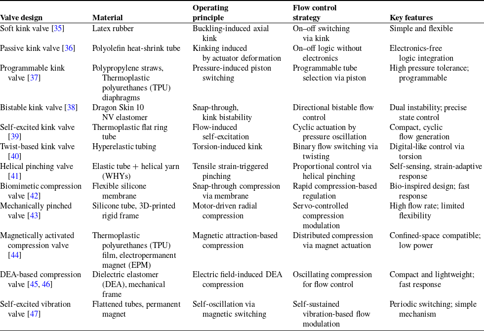
Unlike kink deformation, which primarily relies on localized structural instability, channel compression deformation depends on externally applied radial forces to alter the cross-sectional area of the channel, allowing for precise flow regulation. This method provides adjustable control; unlike the complete opening and closing seen in kink deformation, channel compression enables continuous variations in the degree of deformation, allowing for fine-tuned adjustments to the cross-sectional area and flow resistance. Although channel compression deformation enables precise, continuously adjustable flow regulation, its reliance on externally applied radial forces introduces additional mechanical complexity and may lead to variability in performance under changing operating conditions. Representative soft valves employing these two deformation strategies are summarized in Table I.
Overview of soft valves based on flexible channel deformation.

Overall, kink deformation operates in a manner analogous to digital control, as it enables rapid switching between on-and-off states. In contrast, channel compression deformation functions similarly to analog control, as it allows for gradual and continuous adjustments of the channel’s cross-sectional area, enabling fine-tuned flow regulation. This distinction provides a valuable framework for designing soft robotic fluidic systems, where kink-based mechanisms can be leveraged for binary state transitions, such as fluidic logic circuits, while compression-based approaches offer smooth and precise modulation for tasks requiring continuous variation in flow or pressure.
2.1.2. Physically obstructed channel
Unlike deformation-based methods, which passively alter the channel shape to control flow, physically obstructed channel-based methods achieve fluid regulation through flexible elements that act as active barriers. These components modulate the flow path by undergoing controlled deformation or displacement. In this approach, functional elements – such as elastic membranes, flexible valve cores, and flexible valve flaps – dynamically adjust the channel cross-section, enabling switchable flow control.
Physically obstructed channel-based methods can be further categorized based on the mechanism governing flow obstruction: elastic deformation-based obstruction and displacement-based obstruction. Elastic deformation-based obstruction relies on the inherent flexibility of materials to regulate flow, as shown in Figure 2(c). Components such as soft membranes, valve flaps, or hydrogels deform elastically in response to pressure or external stimuli, altering the channel cross-section. These materials exhibit reversible shape changes, allowing repeated opening and closing without the need for rigid moving parts. In contrast, displacement-based obstruction controls flow by physically repositioning an obstructing component within the channel, as shown in Figure 2(d). This category includes mechanisms where a movable valve core, piston, or sliding element shifts linearly or rotates to open or block the passage. Unlike elastic deformation-based methods, displacement-based obstruction relies on the mechanical movement of distinct structural components, providing a more controlled and repeatable approach to flow regulation.
Several studies have explored how elastic deformation-based obstruction can be leveraged to design efficient soft valves. Napp et al. [Reference Napp, Araki, Tolley, Nagpal and Wood48] designed a passive check valve using a 3D-printed housing and multiple functional components. At low-flow rates, the rubber flap deforms insufficiently to fully block the flow, leading to controlled leakage and hysteresis. As the flow rate increases, the flap deforms enough to seal the orifice, preventing further fluid passage. This design enables gradual flow regulation, ensuring leakage control at low-flow rates and full sealing at high-flow rates. Adjusting the valve flap thickness and orifice diameter allows tuning of the shutoff pressure between 0.037 and 3.16 psi. With its low-cost and low-power operation, this valve is well-suited for pneumatic systems in soft robotics. Inspired by the structure of the biological mitral valve, Gilbertson et al. [Reference Gilbertson, McDonald, Korinek, Van de Ven and Kowalewski49] introduced a soft valve constructed from 8A durometer silicone, featuring three flap-like leaves arranged in a conical pattern. This compliant material imparts the valve with unique pressure-responsive behavior during bidirectional flow regulation. At low internal pressures, the flaps remain sealed to prevent flow, while at higher pressures exceeding a critical cracking threshold, the flaps elastically deform to permit fluid passage. By tuning structural parameters such as flap thickness and cone angle, the valve’s opening pressure can be adjusted to suit specific operating conditions. The use of low-durometer silicone enhances deformation sensitivity, allowing reconfigurability and adaptability across a range of soft robotic applications.
To achieve bidirectional flow control, the conical structure requires a large actuation pressure to invert. However, when replaced by a hemispherical structure and utilizing the snap-through instability of flexible materials, the required inversion pressure can be significantly reduced, and the inversion process also exhibits noticeable hysteresis, which helps minimize interference errors. The principles of snap-through instability are further utilized in refs. [Reference Park, Choi, Kim, Park and Hong50, Reference van Laake, de Vries, Kani and Overvelde51], where elastic deformation of a spherical soft shell with slits achieves valve regulation, as shown in Figure 3(c). In the initial state, the valve maintains its original shape with the slit slightly open. As air flows through the valve, the increased pressure causes the slit to close, completely shutting off the flow. Once the pressure surpasses a critical threshold, the shell undergoes snap-through buckling, inverting its shape and reopening the slit, thus enabling fluid flow regulation. These snap-through-based soft valves exhibit inherent hysteresis and reconfigurability, making them particularly advantageous for pneumatic actuation in soft robotic systems.
Hydrogels, highly water-absorbent crosslinked polymer networks, can retain large amounts of water through hydrogen bonding and undergo reversible deformation in response to external stimuli such as temperature, pH, or light. These properties make them well-suited as key components for channel obstruction in soft robotics. Anisotropic PEG-PNIPA hydrogels, which exhibit two-dimensional anisotropic contraction in response to temperature changes, have been applied as materials for temperature-controlled valves. Wu et al. [Reference Wu, Lin and Sun52] reported that at lower temperatures, the hydrogel remains in an expanded state, effectively blocking fluid flow. As the temperature rises, the hydrogel shrinks, thereby opening the valve and allowing fluid passage. Due to its anisotropic properties, the hydrogel exhibits negligible axial deformation during contraction, which ensures that it remains fixed within the channel. In a separate study, Yu et al. [Reference Yu, Bauer, Moore and Beebe53] leveraged the pH-responsive behavior of hydrogels by shaping them into valve flap-like structures that open or close in response to pH changes. At an applied pressure of 0.71 psi, the valve exhibited a forward flow rate of 140 mL/min, while the backward leakage rate remained as low as 2.3 mL/min, demonstrating its effectiveness in unidirectional flow regulation.
While elastic deformation-based obstruction relies on material flexibility to regulate flow, an alternative approach – displacement-based obstruction – achieves flow control through the physical displacement of structural components. This method regulates the flow by repositioning an internal component, such as a movable valve core, piston, or sliding element, to open or block the passage. Unlike elastic deformation-based obstruction, which depends on material compliance, displacement-based obstruction ensures precise and predictable flow modulation through controlled structural movement. By eliminating material hysteresis and nonlinearity, this approach provides consistent, repeatable performance, making it particularly suitable for applications requiring high accuracy and stability.
Bosio et al. [Reference Bosio, Zrinscak, Laschi and Cianchetti54] developed a miniaturized soft fuse valve composed of medium-soft silicone, which autonomously interrupts fluid flow in response to sudden system failure. The valve consists of a soft-walled shell that houses a mobile internal sphere. Under normal pressure conditions, the sphere remains in its initial position, allowing free fluid flow. However, in the event of a rapid pressure drop and a corresponding increase in flow rate, the hydrodynamic force displaces the sphere into a conical channel section, sealing the passage and preventing further flow. This passive fail-safe mechanism, enabled by the elasticity and resilience of the silicone shell, enhances system reliability. The valve is highly compact, with a volume below 50 mm3 and a weight under 0.10 g, making it well-suited for fluidic safety control in soft robotic systems.
Wang et al. [Reference Wang, He and Maiolino55, Reference Wang, He and Maiolino56] designed a bistable pneumatic valve incorporating a piston-actuated mechanism fabricated from Agilus30, a rubber-like photopolymer material with a Shore hardness of 30A and tensile strength of 2.1–2.6 MPa. The bistable unit is formed by a symmetrically distributed flexible conical shell, which undergoes snap-through instability under controlled pneumatic pressure differences between upper and lower chambers. This transition drives the piston to slide axially, alternately obstructing and opening the fluid channels to regulate flow. The choice of Agilus30 provides both structural compliance and mechanical durability, allowing the valve to achieve adjustable switching pressures ranging from 15.3 to 65.2 kPa, with a response time under 1.8 s and a peak flow rate of 7.42 L/min. The integration of bistable mechanics with elastomeric material properties enables responsive and energy-efficient fluid control in soft pneumatic systems.
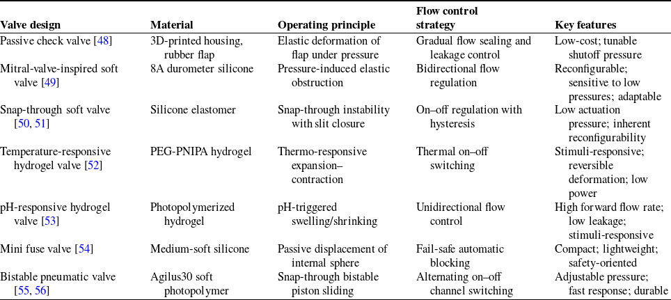
In soft robotic applications, physical obstruction-based soft valves are typically categorized into elastic deformation obstruction and displacement-based obstruction methods. Elastic deformation-based valves utilize materials such as elastic membranes, flexible valve cores, and flexible valve flaps, which can reversibly alter the channel cross-section, providing flexibility and adaptability for repeated use. This approach functions similarly to a flexible switch, where material deformation enables continuous flow regulation, making it suitable for adaptive control systems akin to continuous regulation methods. However, these materials may present challenges in terms of sealing reliability and fluid leakage at lower pressures. In contrast, displacement-based obstruction methods rely on linear sliding or rotational movement to open or close the channel, operating like mechanical switches. This method depends on the movement of solid components to achieve precise and reliable switching at fixed positions, resembling discrete control systems. While this approach offers higher reliability and predictable switching thresholds, it comes at the cost of increased complexity and reduced flexibility. Rigid valves also frequently employ obstruction-based mechanisms for fluid regulation. However, in soft valves, the obstruction mechanism enables on-board regulation, eliminating the need for externally mounted valve structures. This reduces system bulk caused by additional tubing and external actuation components, making soft valves a more viable solution for achieving complete softness in soft robotic systems compared to rigid valves. Representative soft valves employing these two obstruction mechanisms are summarized in Table II.
Overview of soft valves based on physically obstructed channels.

2.2. Rigid valves
Compared to soft valves, rigid valves, which are fabricated from harder materials, cannot adjust the flow channel cross-section by altering their shape. These valves typically regulate fluid flow by mechanically obstructing the channel, often through linear or rotary actuation. Unlike soft valves, which achieve flow modulation through material deformation and geometrical compliance, rigid valves rely on precise mechanical motion to provide higher control accuracy and operational stability in specific application scenarios.
In the context of soft robotics, the term "soft" primarily refers to the compliant morphology and deformable actuation mechanisms that enable safe and adaptive interaction with unstructured environments. However, soft robotic systems often incorporate certain rigid components – such as valves, sensors, or connectors – for the purposes of power transmission, sensing, or control. When integrated appropriately, these rigid elements function as peripheral control modules without compromising the system’s overall compliance. Rigid valves, in particular, are commonly employed to regulate fluid input into soft actuators and do not directly participate in the deformation or environmental interaction processes that define the robot’s softness.
Within such systems, rigid valves serve two primary roles: single-channel on–off control and multi-channel switching. This section focuses on rigid valve designs featuring innovative structures and novel regulation strategies specifically developed for soft robotic applications. Common off-the-shelf rigid valves that are not adapted to the requirements of soft robotic systems are beyond the scope of this review.
Single-channel on–off valves represent the most basic type of rigid valve, primarily used to control gas or liquid flow through simple open-close actions. These valves are often employed to control the opening and closing of a single pneumatic circuit or to achieve complex fluid regulation by combining multiple valves. Such valves typically have two operating states: open and closed. In the open state, gas or liquid flows freely, while in the closed state, the flow is completely blocked. The operation of these valves is performed by actuators, with electromagnetic actuators being the most common.
Electromagnetic valves generate a magnetic field through a solenoid coil, which drives the valve core to control the open or closed state of the valve. Due to this working principle, they are particularly suitable for on–off control of single channels. Marchese et al. [Reference Marchese, Onal and Rus57] proposed an innovative electromagnetic valve in which current pulses through the coil align the magnetic poles of two permanent magnets, AlNiCo and NeFeB, causing an iron ball to move away from the valve seat, thus allowing fluid flow. Conversely, when an opposite current pulse is applied, the magnetic poles repel each other, driving the iron ball back into the valve seat to block the flow. This valve achieves state switching with a 5 ms current pulse and maintains its position without continuous power input. The estimated peak flow rate ranges from 0.35 to 0.37 L/min.
Shen et al. [Reference Shen, Zhang, Wang, Wang and Tian58] proposed an electromagnetically controlled self-vibrating valve, fabricated using 3D printing and integrating a piston, magnet, and return spring. When compressed air enters the soft actuator, it expands, pushing the piston to close the valve. As the pressure drops below a threshold, the return spring reopens the valve, completing the inflation-deflation cycle. Under a driving pressure of 195 kPa, this self-vibrating valve enabled the robot to crawl forward at 49.0 mm/s and backward at 38.2 mm/s. Requiring no external control signals, this autonomous valve facilitates periodic expansion and contraction of the soft actuator, providing a promising mechanism for untethered soft robotic systems. Similarly, Chen et al. [Reference Chen, Tang, Hu, Lin and Zou59] developed a miniaturized magnetically controlled valve that employs a neodymium magnetic ball and a return spring to regulate flow channel obstruction. By manipulating the magnetic field, the position of the magnetic ball can be precisely controlled, enabling dynamic flow regulation. The valve, measuring 11 mm in length and 7 mm in width, is highly compact, and its low fabrication cost of $0.50 per unit makes it particularly suitable for integration into soft robotic applications requiring low-cost and miniaturized components.
Multi-channel switching valves regulate multiple pneumatic circuits or channels, enabling the control of multiple actuators within a single system. Compared to single-channel on–off valves, these valves offer enhanced system integration by reducing the total number of required valves, making them particularly suitable for complex soft robotic systems with dynamic flow regulation needs.
In this context, Kobayashi et al. [Reference Kobayashi, Akagi, Dohta, Cho, Shinohara and Yokota60] developed a multi-channel switching rigid valve based on a slide-gate mechanism to simplify the pneumatic control system of soft robots. This valve employs a rotating cam and multiple gate pins to simultaneously control the supply and exhaust of multiple pneumatic actuators, effectively minimizing system complexity, weight, and the total number of valves required. As a result, it enhances the compactness and cost-efficiency of pneumatic control in soft robots. At an operating pressure of 500 kPa, this valve achieves a flow rate of 42–45 L/min. Zhu et al. [Reference Zhu, Han, Qi, Gong, Yang, Shinshi and Han61] proposed a single-coil-driven tristable electromagnetic mini valve that utilizes the interaction between cylindrical and annular magnets to achieve three stable working states. This design enables a single coil to control the switching of airflow across multiple channels, significantly reducing energy consumption while facilitating the integrated control of multi-degree-of-freedom pneumatic soft robots. Compared to traditional bistable valves, the tristable design offers lower power consumption and a more compact form factor, making it particularly suitable for highly integrated medical pneumatic devices. The valve exhibits a minimum response time of 3.75 ms, operates within a pressure range of 0–200 kPa, and achieves a maximum flow rate of 10.5 L/min with a back pressure tolerance of up to 180 kPa.
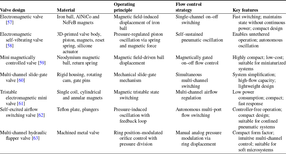
A key application of multi-channel switching valves is in self-excited oscillation, where periodic and autonomous flow switching is achieved without external actuation. This mechanism is particularly valuable for soft robotic systems, enabling efficient and adaptive fluid regulation. Takayama et al. [Reference Takayama and Sumi62] developed an airflow switching valve utilizing self-excited oscillation, which leverages this principle to alternate airflow between different output ports. Compared to electromagnetic valves, this self-excited airflow switching device is compact, eliminates the need for complex electrical control systems, and enhances response speed and adaptability in soft robots by minimizing air supply delays. In addition, the valve’s small form factor (20 mm in diameter and 50 mm in length) enables integration into compact pneumatic systems, making it particularly suitable for soft robots operating within confined spaces. Low et al. [Reference Low, Berg and Li63] introduced a hydraulic valve featuring a ring-type flapper, designed to control the posture of soft robots through multi-degree-of-freedom pressure modulation. This valve simultaneously adjusts the pressure in three channels, manipulating the longitudinal position of the annular flapper to activate different orifices. By varying the distance between the annular structure and the orifice, the valve precisely regulates both pressure and flow rate in each channel, facilitating controlled pressure distribution and coordinated motion of soft robotic actuators. Furthermore, its miniaturized design makes it well-suited for soft robotic applications constrained by size limitations, offering a compact yet effective solution for precise hydraulic control. Representative rigid valves used in soft robotic systems are summarized in Table III.
Overview of rigid valves in soft robots.

2.3. Microfluidic valves
In the past decade, the rapid development of soft robotics has facilitated the application of microfluidic technology within this field [Reference Ranzani, Russo, Bartlett, Wehner and Wood64–Reference Garrad, Soter, Conn, Hauser and Rossiter67]. A microfluidic system primarily comprises micro-sensors, micro-pumps, micro-valves, and other components, with its core function being the driving and control of fluid within channels. Consequently, the driving and control technologies of microfluidic systems serve as the foundational premise of microfluidic technology, with microvalve control being a critical method for regulating fluid flow. Microfluidic valves, commonly referred to as microvalves, are extensively utilized in microfluidic chips, biomedical applications, the electronics industry, and other domains, serving as essential components for fluid drive and control. The operational principles of microvalves differ according to their type. For instance, passive control microvalves typically rely on the physical properties of the fluid or environmental conditions to open, close, or adjust the flow, utilizing natural phenomena such as capillary action, surface tension, and pressure differentials. Common designs include cantilever [Reference Gong, Zhou, Yang and Wang68, Reference Koch, Evans and Brunnschweiler69] and diaphragm microvalves [Reference Mosadegh, Kuo, Tung, Torisawa, Bersano-Begey, Tavana and Takayama70–Reference Shin, Park, Dang, Kimb and Kim72]. In contrast, active control microvalves require external energy input to actuate valve movements, employing mechanisms such as pneumatic [Reference Rhee and Burns73, Reference Baek, Park, Ju, Lee and Lee74], electrostatic [Reference Xie, Shih, Lin, Yang and Tai75], piezoelectric [Reference Truong and Nguyen76], and electromagnetic [Reference Khoo and Liu77]. These valves feature specialized flow channels and leverage the material properties of their mechanical structures to achieve passive control, offering advantages such as ease of manufacture and simplicity of design. Microvalves are primarily employed to manage fluid flow within micro-channels, making them compact and well-suited for low-flow and low-pressure applications. They exhibit notable characteristics, including reliable operation, minimal leakage, low power consumption, high precision, and broad adaptability.
An autonomous robot ``Octobot” [Reference Wehner, Truby, Fitzgerald, Mosadegh, Whitesides, Lewis and Wood78], which is constructed entirely from soft materials, as shown in Figure 4(a). The flow of fluid within the Octobot is regulated by microvalves and microfluidic logic circuits. Fluid is injected into a hydrogen peroxide solution via an injection pump, where gas is generated through the action of a catalyst, thereby controlling the drive and exhaust distribution across the robot’s eight legs. The microfluidic valves work in close coordination with components such as fuel storage, the catalytic reaction chamber, and the actuator network to enable the full functionality of the Octobot.
Microfluidic valves for soft robotics applications. (a) Microfluidic control systems for robot “Octobot”. Reproduced with permission. Ref. [Reference Wehner, Truby, Fitzgerald, Mosadegh, Whitesides, Lewis and Wood78] Copyright 2016, Springer Nature. (b) Microfluidic valves for demultiplexer. Reproduced with permission. Ref. [Reference Bartlett, Becker and Wood79] Copyright 2020, Royal Society of Chemistry. (c) 3D-printed multi-material microfluid valve. Reproduced under the terms of the CC-BY license. Ref. [Reference Keating, Gariboldi, Patrick, Sharma, Kong and Oxman81] Copyright 2016, Public Library of Science. (d) Microfluidic valves for the 12-layer soft ``spider” apparatus. Reproduced with permission. Ref. [Reference Ranzani, Russo, Bartlett, Wehner and Wood64] Copyright 2018, Wiley.

Furthermore, a soft microfluidic demultiplexer is a potential control system for soft robots [Reference Bartlett, Becker and Wood79], as shown in Figure 4(b). This demultiplexer can streamline the control circuitry and can enhance the functionality of soft robots by employing a more concise and efficient design architecture for the microfluidic valves, which utilize two vertically aligned and slightly offset microchannels, along with a deformable diaphragm to regulate fluid flow, thereby achieving more precise control of the microfluidic system.
The passive microfluidic control valve, known as the Microfluidic Air-intake and eXhaust (MAX) valve [Reference Lin, King and Wehner80], enables centimeter-level unrestrained circulating combustion in soft robots. This valve achieves self-regulation of air intake and exhaust through its structural and functional design, facilitating energy autonomy in soft robots. Additionally, a concept of a continuous on–off valve is introduced within the microfluid valve, allowing for seamless switching between two fluid configurations, thereby enabling dynamic flow regulation. As shown in Figure 4(c), the 3D-printed multi-material microfluid valve [Reference Keating, Gariboldi, Patrick, Sharma, Kong and Oxman81], integrates the functions of a sensor and control valve, achieving precise proportional control of fluid through a rigid-flexible multi-material design. This integrated approach overcomes the limitations of traditional microfluidic valves, enhancing the accuracy and flexibility of microfluidic device control. It lays the groundwork for the development of programmable and automated microfluidic devices, which can be utilized in various complex fluid regulation scenarios, including DNA assembly and analysis, continuous sampling and sensing, and soft robotics. As shown in Figure 4(d), the ``Microfluidic Origami for Reconfigurable Pneumatic/Hydraulic Pressure” (MORPH) system [Reference Ranzani, Russo, Bartlett, Wehner and Wood64] creates a three-dimensional soft microstructure with embedded microfluidic circuits by combining multi-layer soft lithography and bulk micromachining. The microfluid valve serves as a key component, embedded within the complex three-dimensional structure and working in conjunction with other components to form a highly integrated system. In the 12-layer soft ``spider” apparatus, the microfluidic valve facilitates precise fluid control across different sections through interlayer design and channel layout, enabling each sub-laminate of the spider to bend and straighten its legs, as well as deform its head and abdomen.
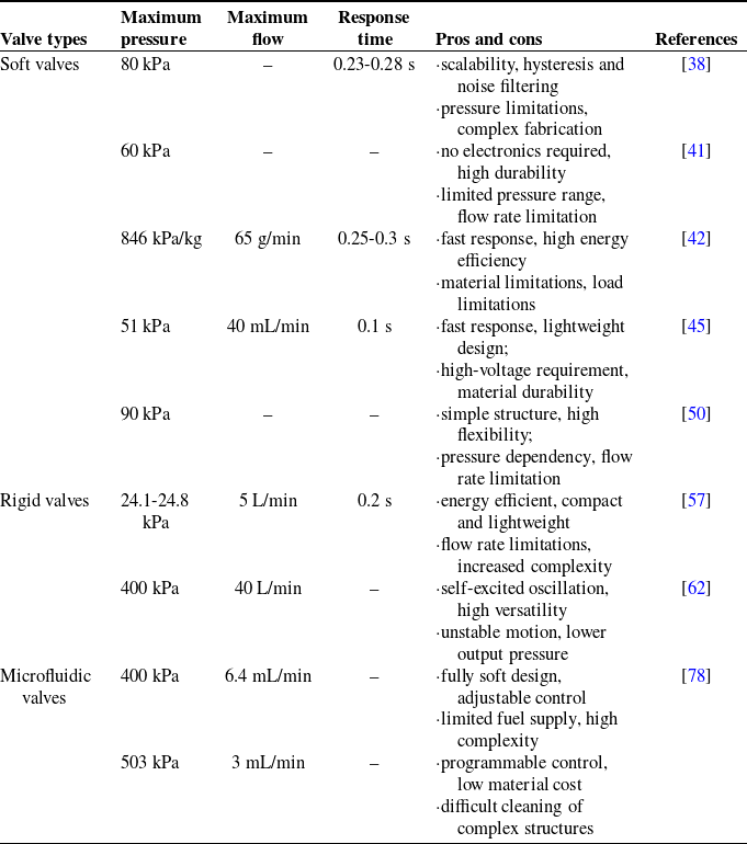
In soft robots, valve-based fluid regulation strategies can be categorized into soft valves, rigid valves, and microfluidic valves. Soft valves primarily control the opening and closing of the valve through the deformation of flexible channels or by physically obstructing the flow channels. Rigid valves regulate flow by blocking the channel, enabling control over a single flow channel or facilitating the switching between multiple channels. Microfluidic valves are specifically utilized to manage fluid flow within microchannels. The performance metrics, as well as the advantages and disadvantages of representative examples, are systematically summarized in Table IV.
Performance indicators of different types of valves.

3. Fluid regulation strategies based on smart fluids
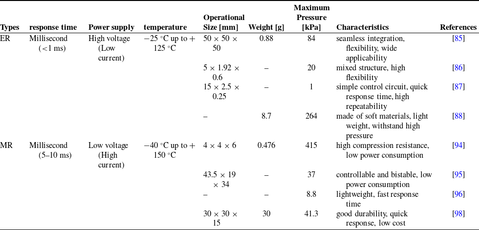
The characteristic of smart fluids is their ability to change their flow properties, primarily viscosity, in response to the application of an electric or magnetic field. These fluids are classified into two main types: electrorheological (ER) fluids and magnetorheological (MR) fluids. ER fluids consist of a dielectric liquid medium and easily polarizable filler particles, [Reference Ranzani, Russo, Bartlett, Wehner and Wood64] while MR fluids are composed of magnetic particles suspended in a nonmagnetic oil medium [Reference McDonald and Ranzani25]. The fundamental flow mechanisms of both types of fluids are similar; in ER fluids, the electric field polarizes the semiconductor particles, while in MR fluids, the magnetic field aligns and magnetizes the magnetic particles, making them linear and thus regulating their flow behavior. When no electric or magnetic field is applied, the particles are randomly distributed, however, when an electric or magnetic field is applied, the particles will align in a chain-like distribution due to the effects of the field, as shown in Figure 5. When the electric or magnetic field is removed, the changes in these fluids can be reversed, allowing for dynamic and reversible control of their rheological behavior. By applying electric and magnetic fields and utilizing the unique characteristics of intelligent fluids, the viscosity coefficient of soft robots can be dynamically changed. Therefore, soft robots can effectively control fluid transmission, utilizing the responsive characteristics of the fluid to achieve the desired fluid behavior.
Schematic diagram of ERF and MRF.

3.1. Electrorheological fluids
ERF can typically transition from liquid to solid in a repeatable and reversible manner within milliseconds [Reference Halsey82]. When an electric field is applied, the particles are instantaneously polarized into electric dipoles, and the interactions between particles cause solid particles to form chains, leading to a columnar structure. The formation of this structure increases the viscosity and yield stress of the fluid, effectively solidifying it [Reference Wen, Huang and Sheng83]. Therefore, based on this characteristic of ERF, Sadeghi et al. [Reference Sadeghi, Beccai and Mazzolai84] proposed the design and development of a composite electromagnetic valve based on ERF to control the flexibility of soft robots by regulating the flow of the electromagnetic fluid. The electromagnetic valve provides a soft structure, where the movement of each soft joint generates a flow of the internal fluid between two connected vessels through the internal fluid valve. By activating the ER valve, the flow and subsequent joint degrees of freedom can be blocked, thereby increasing the controllability of the soft robot’s degrees of freedom. Huang et al. [Reference Huang, Xu, Zhang, Bai, Aravelli, Zhou and Han85] proposed a novel double-flow concentric semi-cylindrical flexible ER valve, which utilizes the fast response and precise control characteristics of ERF to enable soft robots to achieve large deformation bending motion in multiple motion modes. The ERF used is composed of urea-coated barium titanyl oxalate nanoparticles dispersed in silicone oil, as discovered by Wen et al. This valve has an overall volume of 50 mm3, a mass of 0.88 g, and a maximum control pressure of 84 kPa. It can be seamlessly integrated into hydraulic network actuators, achieving six motion modes without affecting the flexibility of the actuators, making it suitable for most soft robot applications. To improve the flexibility of ER valves and overcome the limitations of traditional structures in terms of deformation ability, Sudhawiyangkul et al. [Reference Sudhawiyangkul, Yoshida, Eom and Kim86] proposed an innovative design of a cantilevered flexible microvalve based on ER fluid. The valve adopts a composite flow channel structure of polydimethylsiloxane (PDMS) and SU-8: PDMS endows the flow channel with high flexibility to achieve flexible deformation, while SU-8 material significantly inhibits structural expansion under high pressure due to its low expansion characteristics. The synergistic effect of the two ensures valve flexibility while improving structural stability. By regulating the external electric field strength, the apparent viscosity of the ER fluid can be changed in real time, thereby achieving precise control of flow velocity in the channel.
Tonazzini et al. [Reference Tonazzini, Sadeghi and Mazzolai87] further explored the application prospects of ER valves in the field of flexible fluid drive and designed a multi-layer electrode structure ER solenoid valve to simplify the actuator circuit system. The core structure consists of two parallel planar electrodes sandwiching an insulating layer with grooves, and the groove space is sealed by the electrodes to form a fluid channel connecting the inlet and outlet of the valve body. Research has shown that when an electric field is applied, the viscosity of the ER fluid increases significantly, creating a significant pressure difference that completely blocks fluid passage. The valve can withstand pressures up to 1 MPa when closed, demonstrating excellent fluid blocking performance.
In order to enable robots to be composed of more soft components and further allow soft robots to interact safely with the environment, Zatopa et al. [Reference Zatopa, Walker and Menguc88] developed a fully soft hydraulic control valve based on ERF. The valve is composed of 3D printed photopolymer material, with gallium indium tin liquid metal alloy as the electrode, weighing 8.7 g. Under strain conditions such as bending, twisting, and stretching, the maximum holding pressure of the valve achieves 264 kPa when 5 kV is applied, further realizing the goal of fully soft controllable robots. Behbahani et al. [Reference Behbahani and Tan89] developed a multi-layer composite flexible robotic fin, utilizing ERF as the working fluid, leveraging the property of ERF that causes changes in viscosity, yield stress, and other fluid characteristics under an electric field to adjust stiffness. Due to the millisecond response time of ERF, this also provides a rapid solution for stiffness adjustment. Sadi et al. [Reference Sadi, Holthausen, Stallkamp and Siegfarth90] introduced a novel hydraulic actuator module based on ERF, which operates using ERF, ensuring miniaturization while still possessing a strong driving force. Choi et al. [Reference Choi, Park and Cho91] proposed a method for position control of robotic arms using ER valves. This method improves precision and response time based on the rapid response performance of ERF.
3.2. Magnetorheological fluids
The MR effect is typically attributed to the field-induced magnetization of suspended particles. When a magnetic field is applied, the particles become magnetized along the magnetic lines and attract each other, forming anisotropic aggregates across the system [Reference Kim, Yoshida, Kouda and Yokota92], resulting in materials that typically exhibit higher yield stress than similar materials like ER fluids. Therefore, MRF is becoming increasingly important in the application of soft robots and has great potential [Reference Dong, Seo and Choi93], especially in the research of MR valves. Leps et al. [Reference De Vicente, Klingenberg and Hidalgo-Alvarez94] introduced a low-power, interference-resistant magnetorheological valve using an electromagnetic permanent magnet. This valve uses MRF as the working fluid and employs an electromagnetic permanent magnet to induce reversible blockage in the MRF. The valve can prevent flow at pressures up to 180 kPa and can maintain over 415 kPa pressure once blockage occurs, consuming zero steady-state power and minimal switching energy. Balak et al. [Reference Bossis, Lacis, Meunier and Volkova95] introduced a bistable valve for a soft robotic drive system based on MRF. This valve is controllable and bistable, requiring power only to switch between open and closed states, thereby reducing power consumption and preventing overheating. The valve consists of a lever arm with two permanent magnets and an electromagnet, which replaces the lever arm by applying a magnetic force to one of the permanent magnets, while the other permanent magnet is used to harden the magnetorheological fluid. The high magnetic field strength of the neodymium permanent magnet allows the magnetorheological fluid to harden through thick pipe walls and maintain a large pressure differential. McDonald et al. [Reference Leps, Glick, Ruffatto, Parness, Tolley and Hartzell96] introduced a flexible robot control platform using magnetorheological fluid as the working fluid and proposed a magnetorheological fluid valve that uses a magnetic field to control the pressure inside a continuous flow fluid actuator. The application of the magnetic field will directly affect the pressure drop in a given region of the fluid, enabling the integration of the valve. McDonald et al. [Reference Balak and Mazumdar97] also proposed an improved method for controlling soft robots using MRF by introducing an electromagnetic permanent magnet as an electronic control magnetic field source.
To address the challenge of insufficient response speed and accuracy of fluid control valves in soft robots, Wang et al. [Reference McDonald, Rendos, Woodman, Brown and Ranzani98] designed a soft robot proportional valve based on a magnetorheological elastomer (MRE) membrane. The driving unit of this valve is an electromagnetic coil embedded in silicone resin, which can generate a controllable magnetic field through current excitation and directly act on the MRE membrane to achieve dynamic control: when the coil is not powered, the MRE membrane is in a free state, allowing air circulation; after applying current, the magnetic field magnetizes the MRE film and pulls it toward the magnetic field concentration area, gradually compressing the cross-sectional area of the channel. By adjusting the current intensity, complete interruption of airflow can be achieved. Experiments have shown that the valve can stably withstand a working pressure of 41.3 kPa, but its application is still limited by issues such as magnetic interference, nonlinear flow deviation, and coil overheating. Therefore, in subsequent research, Wang et al. [Reference McDonald99] proposed a two-dimensional MRF proportional valve array design, providing an optimal array layout to ensure sufficiently low magnetic interference and addressing issues of magnetic interference and overheating when scaling from a single MRF proportional valve to an integrated array.
In the performance optimization study of MRE-driven valves, Bose et al. [Reference Wang, He, Albini, Zhang and Maiolino100] systematically investigated the coupling effects of material and process parameters on valve characteristics. Its research focuses on the key performance of soft MRE as valve body actuators, and experimentally verifies that material parameters (such as the hardness of the elastomer matrix) and process parameters (such as curing conditions) can significantly regulate the dynamic response characteristics of the valve. Research has found that the hardness of the elastic matrix in MRE is the dominant factor determining the output force and deformation capacity of valves, providing clear material selection and process optimization directions for the design of soft valves.
Some researchers have innovated in soft robotics by utilizing the properties of magnetorheological fluids. Williamson et al. [Reference Wang, Zhang, He and Maiolino101] proposed using the properties of magnetorheological fluids to extend the operational range of single-chamber inflatable soft robots. They drew inspiration from the movement of sea cucumbers, using the increase in apparent viscosity of magnetorheological fluid exposed to a magnetic field to alter the wall stiffness of the single chamber, thereby changing its expansion-dependent motion. Experimental results indicate that by changing the magnetic field applied to the magnetorheological fluid in the channel, the stiffness of various regions of the chamber wall can be significantly altered, with the stiffness of the active material changing by a factor of two. Compared to robots with uniform rubber components, the working volume of these robots increased sixfold. McDonald et al. [Reference Böse, Rabindranath and Ehrlich102] proposed a dynamic magnetic field control scheme based on electric permanent magnets (EPMs), which achieves pressure control of soft actuators by adjusting the rheological properties of MRF in real time. This study integrates a continuously flowing MRF and a programmable EPM array into a multi-degree-of-freedom soft robot system, achieving precise spatial control of the magnetic field acting on the MRF through an electronic control strategy. This enables researchers to dynamically change the viscosity characteristics of MRF by adjusting the magnetic field distribution parameters, thereby regulating the fluid pressure conduction mechanism inside the soft actuator. Hua et al. [Reference Williamson, Schell, Keller and Schultz103] proposed a novel soft robot that combines a magnetorheological magnetic drive system with crawling motion. MRF is a superparamagnetic material that can be magnetized or demagnetized within milliseconds by applying or removing a magnetic field, without generating any coercive force. Since the crawling motion of the robot is generated by anisotropic magnetic torque, when the magnetic field is turned off, the magnetorheological fluid particles do not produce magnetic coercive force, allowing the two components of the robot to avoid magnetic interference and enabling continuous drive-release motion, thus achieving efficient locomotion. This offers great potential for the development of advanced magnetic soft robots in the future.
ERF has a faster response speed than MRF. ERF responds rapidly to changes in electric fields, capable of altering flow characteristics within milliseconds. By adjusting the electric field strength, the viscosity of the fluid can be precisely controlled. When the electric field is turned off, the fluid can maintain its flow state, making it suitable for applications requiring static control. Under the action of an electric field, the rheological properties of ERF change reversibly and can be reused repeatedly. Furthermore, ERF is compatible with various materials and has a range of applications, such as in dampers, clutches, valves, and actuators [Reference McDonald, Kinnicutt, Moran and Ranzani104], potentially providing solutions for more diverse fields [Reference Hua, Liu, Sun, Sotelo, Li and Li105]. However, ERF requires high-voltage operation and insulation design, which increases the complexity of the system. And its yield stress is low, making it difficult to use in high-load scenarios. In addition, the performance of the fluid may be affected by temperature changes, impacting stability.
MRF can rapidly change its flow characteristics under a strong magnetic field, making it suitable for dynamic control. Once the magnetic field is removed, the fluid can quickly return to its original state. MRF can complete the transition from low viscosity fluids to high viscosity solids in milliseconds. The strength and direction of the magnetic field can be flexibly adjusted. In addition, the maximum yield stress of MRF is much greater than that of ERF. The temperature range of MRF is relatively large, and the stability of magnetic particles is better. These allow MRF to adapt to various working conditions. MRF products have between 20 and 50times higher control effect than the equivalent ERF products. It is applicable in various fields such as dampers, prosthetic knees, valves, brakes, clutches, and precision machining [Reference Chauhan, Kumar and Sham106]. However, MRF requires a strong magnetic field to function, which necessitates additional equipment and energy consumption. Moreover, high-performance MRF and related equipment are costly, often requiring the use of magnetic particles, which limits the composition of the fluid. The main parameters and characteristics of typical examples of control methods based on smart fluids are summarized in Table V.
Comparison of control methods based on smart fluids.

4. Fluid regulation strategies based on pressure sources
As the fundamental power source in fluid-driven systems, the performance of the pressure source plays a pivotal role in determining the pressure, flow rate, and overall operational stability of the system. The pressure source is tasked not only with moving fluid across different points but also with ensuring the consistent and stable operation of the system by regulating both flow and pressure [Reference Onal and Rus107–Reference Luo, Tao, Chen, Khuu, Ozel and Onal109]. This process involves factors such as fluid delivery efficiency, precise pressure control, and maintaining reliability under diverse operating conditions. For soft robots, the pressure source must exhibit rapid response capabilities to swiftly adjust to varying dynamic environments and task demands. Moreover, the output pressure is critical in influencing the robot’s mobility and grasping abilities. Therefore, the pressure source must generate sufficient driving force to fulfill the requirements of complex tasks. Careful attention to the design and material selection of the pressure source is essential to meet these performance standards, ensuring rapid response times, high-pressure output, and long-term stability.
4.1. Driven by traditional pressure source
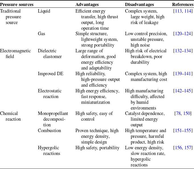
In the field of soft robots, fluid drive technology is crucial for achieving flexible, powerful, and efficient motion [Reference Remy, Brei, Bruder, Remy, Buffinton and Gillespie110]. Traditional pressure sources, as integral components of fluid drive systems, play a significant role in the motion control of soft robots. They greatly simplify the complexity of the control system by directly supplying fluid pressure to drive the actuators, enabling various deformations and movements [Reference Rus and Tolley1]. Fluid-driven systems that incorporate valves are influenced by factors such as fluid pressure, flow rate, valve structure, and cooling devices. In contrast, traditional pressure sources use the compression characteristics of liquids or gases to generate fluid pressure. This approach not only streamlines the system structure but also reduces heat generation, thus improving overall energy efficiency [Reference Song, Cui, Cao, Cao, Park and Dempster111].
The traditional fluid-based pressure source employs the incompressibility of the liquid medium to generate pressure through a hydraulic pump, which forces the fluid into the actuator’s cavity, thereby initiating deformation and producing mechanical motion. This method typically regulates the fluid’s pressure and flow directly via a control system to achieve control over the robot’s motion trajectory and speed, resulting in high-force output and excellent stability [Reference Jelali and Kroll112]. Katzschmann et al. [Reference Katzschmann, Marchese, Rus, Hsieh, Khatib and Kumar113, Reference Katzschmann, DelPreto, MacCurdy and Rus114] developed a soft robotic fish that utilizes water as the transmission medium, employing a hydraulic pump to directly push water into the piping system within the fish’s body, the hydraulic pump is shown in Figure 6(a). By precisely regulating the flow and pressure of the liquid through the hydraulic pump, the caudal and lateral fins of the robotic fish can achieve fish-like propulsion and steering motions, enabling the robot to autonomously adjust its swimming direction and speed. An underwater crawling robot [Reference Tan, Chen, Liu, Zou, Yi, Liu and Wang115] integrates rigid and flexible components with a valveless hydraulic drive, facilitating multi-joint motion control. The hydraulic pump, acting as the core power source, adjusts flow direction, rate, and volume to drive actuator expansion and contraction. Sinatra et al. [Reference Sinatra, Teeple, Vogt, Parker, Gruber and Wood116] proposed a flexible robotic gripper that relies on the adjustment of the hydraulic pump’s output pressure to achieve the desired grasping force, aimed at nondestructively grasping fragile underwater organisms. The hydraulic pump injects fluid into the gripper’s flexible cavity, causing it to expand and generate a gentle gripping force that can be adapted to the flexible gripping requirements of various organisms, as shown in Figure 6(b). These examples highlight the benefits of hydraulic drive systems that do not rely on valves, simplifying design and reducing hardware costs while enhancing fluid transfer efficiency. Moreover, such systems are well-suited for extended operations in dynamic, complex environments [Reference Shi, Tan, Zhang and Liu117].
Schematic diagram of traditional pressure source (a) A traditional fluid-based pressure source in a soft robotic fish. Reproduced with permission. Ref. [Reference Katzschmann, Marchese, Rus, Hsieh, Khatib and Kumar113] copyright 2016, Springer Nature. (b) A traditional fluid-based pressure source flexible gripper for grasping underwater organisms. Reproduced with permission. Ref. [Reference Sinatra, Teeple, Vogt, Parker, Gruber and Wood116] copyright 2019, The American Association for the Advancement of Science. (c) A traditional gas-based pressure source-driven flexible joint for soft robots. Reproduced with permission. Ref. [Reference Jiao, Ji, Zou, Yang and Pan123] copyright 2018, Wiley. (d) A traditional gas-based pressure source-driven linear flexible joint. Reproduced with permission. Ref. [Reference Yang, Verma, So, Mosadegh, Keplinger, Lee, Khashai, Lossner, Suo and Whitesides124] copyright 2016, Wiley.

The traditional gas-based pressure source employs variations in the air pressure of compressed gas to operate a soft robot. Specifically, a compressor is initially used to compress the gas and store it in a gas tank. Subsequently, the compressed gas is utilized to actuate the mechanical components (e.g., piston or diaphragm) within the pneumatic pump, facilitating the suction and discharge of fluid through pressure changes in the pump chamber, thereby powering the actuator’s motion [Reference Zhang and Calderon118, Reference Gollob and Roche119]. Kohll et al. [Reference Kohll, Cohrs, Walker, Petrou, Loepfe, Schmid Daners, Falk, Meboldt and Stark120] proposed a pneumatically driven soft pump to investigate its fluid regulation strategies and long-term operational performance. The pump operates using 200 kPa compressed air, which periodically inflates and exhausts the pump chamber, thereby driving two discharge chambers to alternately discharge fluid. During inflation, the air pressure increases, causing the center chamber to expand, which compresses both discharge chambers and expels fluid; during exhaust, the discharge chambers revert to their original state and are refilled with fluid. By optimizing the pneumatic pressure circulation system, the pump can achieve up to one million cycles with high efficiency. Gorissen and several other scholars [Reference Gorissen, Chishiro, Shimomura, Reynaerts, De Volder and Konishi121, Reference Gong, Yang, Xie, Wang, Kulkarni, Hobbs and Mazzeo122] have proposed a variety of pneumatically driven torsional actuators based on pneumatic pressure. These devices utilize positive pressure to facilitate both torsional and linear motions; however, positive pressure-driven systems often carry the risk of complex structures or excessive pressure. One study [Reference Jiao, Ji, Zou, Yang and Pan123] discusses a vacuum-driven fluid control system that regulates the gas pressure within the actuator cavity by directly adjusting the pumping volume of a vacuum pump, as shown in Figure 6(c). The negative-pressure drive system of the pneumatic pump is deemed safer and more efficient than its positive-pressure counterpart and is capable of generating substantial force output in low-pressure environments, making it suitable for flexible joints and rotating devices in soft robots. The Harvard team [Reference Yang, Verma, So, Mosadegh, Keplinger, Lee, Khashai, Lossner, Suo and Whitesides124] proposed a fluid-driven system for controlling linear actuators by applying either positive or negative pressure via a pneumatic pump. When the pneumatic pump expels air, the actuator undergoes linear contraction, while deflating the air allows the actuator to revert to its initial state, as shown in Figure 6(d). This combination of positive and negative pressure driving mechanisms offers efficient and flexible motion modes for soft robots. In comparison to traditional liquid-based pressure sources, gas pressure sources are simpler, more cost-effective, and environmentally friendly. They offer increased adaptability, safety, and cushioning effects [Reference Rus and Tolley1, Reference El-Atab, Mishra, Al-Modaf, Joharji, Alsharif, Alamoudi, Diaz, Qaiser and Hussain17, Reference Walker, Zidek, Harbel, Yoon, Strickland, Kumar and Shin125].
The above analysis of two traditional pressure sources underscores their significance in fluid regulation strategies for soft robots. Each traditional pressure source, whether based on liquid or gas, possesses distinct advantages and is suited to different application requirements. Liquid-based pressure sources are particularly advantageous in applications requiring good positioning accuracy and long-term operational stability, where maintaining a consistent pressure differential is critical. Gas-based pressure sources are widely used in systems where speed of response is a priority, especially where dynamic configuration capabilities are required. However, fluid control systems that rely solely on pressure sources to alter the fluid state lack valves for precise flow distribution, which may lead to reduced accuracy in multi-degree-of-freedom control and complex motion patterns. Furthermore, fluid control systems that do not incorporate valves often experience inadequate response speeds in scenarios demanding rapid responses or precise feedback regulation [Reference Coyle, Majidi, LeDuc and Hsia6, Reference Wang, Totaro and Beccai126].
4.2. Driven by electric and magnetic field
Electromagnetic field-driven pressure sources have shown significant potential for fluid control systems in soft robots [Reference Zhang, Zhang, Guan, Zhang and Jiao127]. This pressure source leverages the inherent deformation characteristics of specialized materials, which deform their structure in response to externally applied electric fields, magnetic fields, or self-generated electrostatic fields. This deformation enables dynamic adjustments of the volume and pressure within the fluid cavity, thus providing a precise and efficient driving force for fluid control [Reference Hines, Petersen, Lum and Sitti128]. The crux of this technology lies in its capacity to flexibly modify the state of the fluid, allowing soft robots to execute a variety of operations across diverse and complex environments [Reference El-Atab, Mishra, Al-Modaf, Joharji, Alsharif, Alamoudi, Diaz, Qaiser and Hussain17].
Dielectric elastomer (DE) is a polymer material characterized by exceptional electrical and mechanical properties, enabling it to produce substantial mechanical deformation and displacement when subjected to an electric field. Its inherent elasticity and flexibility facilitate rapid recovery after deformation while maintaining relatively low energy consumption during the actuation process. When the DE-film is positioned between compliant electrodes, it functions analogously to a capacitor, deforming in response to applied voltage. This fast-response structure is referred to as a dielectric elastomer actuator (DEA), representing a promising actuation technology in the realm of fluid control for soft robots [Reference Gupta, Qin, Wang, Godaba and Zhu129–Reference Keplinger, Li, Baumgartner, Suo and Bauer131]. The working principle of the pressure source based on DE is shown in Figure 7(a). Building upon this concept, a soft pump [Reference Xu, Nunez, Souri and Wood132] designed to generate peristaltic flow has been introduced, wherein the pump body comprises multiple DEA structures integrated with a soft channel. By applying a sinusoidal voltage signal to the DEA, the indenter in contact with the soft channel undergoes deformation, thereby compressing the soft channel in a controlled manner and providing a driving force for the peristaltic flow of the fluid. Additionally, another variant known as the soft dielectric elastomer peristaltic pump (DEPP) [Reference Mao, Huang, Liu, Li, Qu and Yang133, Reference Mao, Wu, Fu, Chen, Natani, Gou, Ruan and Qu134] consists of four layers of dielectric elastomer film configured to create a circuit-like parallel effect, facilitating high-flow fluid transfer driven by a square-wave voltage with a maximum average flow rate of 2.5 L/min. In specific application scenarios, soft pumps not only need to transfer fluids efficiently but also must meet particular requirements regarding the pumping volume per cycle [Reference Wang, Overvelde J.T., Engelbrecht, Bjørk and Bahl135]. To enhance the pumping volume per cycle, some researchers [Reference Li, Wang, Foo, Godaba, Zhu and Yap27] have proposed an innovative structure wherein a DE membrane is secured to a cylindrical pump chamber, capable of pumping up to 110 mL in a single cycle. Collectively, these findings suggest that dielectric elastomer (DE)-based fluid control technology is distinguished by its lightweight nature and low energy consumption. Furthermore, the fluid control performance of DE pumps can be enhanced through the optimization of electrode design and material composition.
Pressure sources driven by electric and magnetic fields (a) Schematic diagram of pressure sources based on DE (b) Schematic diagram of pressure source based on electrostatic reaction.

Based on dielectric elastomers (DE), the concepts of magnetically coupled dielectric elastomer (MCDE) and dielectric fluid (DF) have been proposed to improve fluid control in soft robotics. MCDE integrates the properties of dielectric elastomers and magnetic materials, enabling deformation under the simultaneous influence of electric and magnetic fields to drive the fluid. This approach enhances the driving performance of dielectric elastomers while providing multi-degree-of-freedom deformation capabilities, allowing for the generation of more complex motions with greater adjustability [Reference Conn, Gao, Cao, Bar-Cohen and Anderson136–Reference Cao, Hill, Conn, Li and Gao138]. The tapered DE configuration offers a simple structure and substantial driving force. However, the design of the double-tapered DE introduces the issue of rigid coupling, despite further enhancing the driving force. A soft pump [Reference Cao, Gao and Conn139] based on MCDE has been proposed, where two identical magnets are positioned at the centers of the upper and lower sections of the biconical DE-film to generate magnetic repulsion. When voltage is applied to the DE membrane, it expands or contracts in-plane, disrupting the equilibrium between the DE membrane and the magnetic repulsive force until the membrane deforms sufficiently to establish a new equilibrium point. Compared to traditional DE pumps, this magnetic coupling not only increases the single pumping volume but also enhances drive flexibility. An MCDE-based pneumatic diaphragm pump [Reference Dai, Du, Zhao, Cao, Li and Gao140] employs magnets positioned externally to the diaphragm and within the diaphragm cavity to generate magnetic attraction. When no voltage is applied, the DE diaphragm is situated below its initial level. Upon the application of voltage for a specified duration, the DE diaphragm undergoes downward deformation. Once the voltage is removed, the DE diaphragm reaches its lowest point and begins to ascend. Due to inertia, its peak position exceeds the initial level, thereby facilitating fluid movement. By adjusting parameters such as the magnetic field strength of the magnets, the initial distance between the magnets, and the intensity of the applied electric field, the performance of the MCDE pump can be optimized to achieve maximum flow output. Additionally, a DF-based bladder-bag soft pump [Reference Lin and Liu141] has been proposed, which stimulates the bladder bag to deform by applying voltage, thereby expelling liquid from the end of the tube body. This DF-driven bladder-like soft pump, which lacks rigid components, offers greater flexibility in application scenarios compared to DE pumps.
Electrostatic actuation is a significant fluid control technique in which an electrostatic field is generated by applying a voltage between conductive electrodes. The electrostatic force, also known as the Coulomb force, is employed to regulate fluid pressure and flow rate, thereby controlling the motion of fluid within a chamber. The basic principle of relying on electrostatic force to drive the pressure source is shown in Figure 7(b). Acome et al. [Reference Acome, Mitchell, Morrissey, Emmett, Benjamin, King, Radakovitz and Keplinger142] proposed an electrostatically driven, pancake-shaped soft pump that integrates electrostatic and hydraulic mechanisms to harness the displacement of a liquid dielectric under the influence of electrostatic force. This pump consists of a discus-shaped elastomer shell, an internal liquid dielectric, and circular rigid electrodes mounted at the center of both the upper and lower sides of the shell. By applying voltage to the electrodes on either side, the internal liquid dielectric is driven to one side due to the electrostatic force, causing the middle section of the discus-shaped shell to deform concavely and squeeze the liquid flow. Additionally, multiple soft pumps can be aligned longitudinally to achieve high-flow fluid drive. Similarly, an electrostatic-driven, high-density elastomer microfluidic system [Reference Chang and Maharbiz143] has been proposed, utilizing a capacitor structure formed by thin-film metal sheets and polydimethylsiloxane (PDMS) to drive the flow of PDMS in the elastomer via electrostatic force, which shows promise for applications in the MEMS field. Another study [Reference Cacucciolo, Shintake, Kuwajima, Maeda, Floreano and Shea144] introduced a charge injection-based soft pump that enables bidirectional fluid pumping by applying a high voltage between electrodes to generate a charge injection effect, thus driving the flow of dielectric fluid in a multi-bending double-open channel. Notably, both the electrodes and the pump body of this device are made from stretchable materials, allowing for continuous operation under highly bending and stretching conditions. An electrostatically driven, origami-based soft pump [Reference Zhao, Yu, Zhang, Sun and Xu145] has been proposed to leverage the self-recovery capability of the Kresling origami structure, enabling both compression and self-recovery for larger strokes. By applying a DC voltage to the electrodes located on the pump wall and bottom, the dielectric liquid within the electric field is induced to move. This movement causes the electrodes to approach each other, resulting in a ‘zipper-type’ contraction that expels gas from the pump. Upon removal of the voltage, the unique Kresling origami structure recovers due to its inherent elasticity, allowing it to re-intake air and complete the cycle. This innovative design significantly enhances pumping efficiency and output pressure, addresses the limitations of traditional air pumps, such as their large size and low-flow rate, and showcases the potential of electrostatic drive technology in precision fluid management.
In summary, electromagnetic field-based pressure source technology provides a diverse range of fluid-driven solutions for soft robotics, with each approach offering unique advantages tailored to specific applications. DE-based fluid-driven pumps are particularly valued for their high flexibility and low energy consumption, making them well-suited for lightweight and energy-efficient robotic systems. In contrast, MCDE-based technology enables multi-degree-of-freedom motion, enhancing adaptability and providing greater versatility for complex robotic movements. In addition, DF exhibits superior insulating properties, making it highly suitable for high-voltage environments. These materials offer enhanced safety by minimizing the risks of electric shock or leakage while demonstrating rapid dynamic response capabilities. Furthermore, electrostatically driven fluid pumps stand out for their compact size and low power consumption, making them the preferred choice for high-precision fluid control in micro and nanoscale applications. With continuous advancements in material science and manufacturing technology, these fluid-driven technologies are expected to achieve greater scalability and durability, unlocking new possibilities for soft robotic applications across a wider range of fields.
4.3. Driven by chemical reaction
Chemical drive differs from pressure drive and magnetic drive in that its energy originates from the energy changes associated with chemical reactions. These reactions convert chemical energy into mechanical or kinetic energy, enabling motion. There are three prevalent types of chemical reactions involved: monopropellant decomposition, combustion, and hypergolic reactions [Reference Chen, Cao, Sarparast, Yuan, Dong, Tan and Cao146]. Mnopropellant decomposition is an exothermic process that occurs in the presence of a catalyst, eliminating the need for a separate oxidant and allowing for the gradual production of gases that can accumulate to provide thrust. For instance, liquid solvents can yield substantial amounts of gas when catalyzed. Combustion is the reaction of a substance with oxygen, usually producing heat and light. Most combustion processes require oxygen. The fuel reacts with an oxidizing agent to produce heat, light, and gases (e.g., carbon dioxide, water vapor, etc.). A hypergolic reaction means that the two chemicals spontaneously ignite and react when they come into contact without the need for an external ignition source. Hypergolic reactions process produces considerable quantities of gas and heat energy, which can be harnessed to generate mechanical or kinetic energy for propulsion [Reference Levikhin and Boryaev147, Reference Yang, Ren, Jiao and He148].
Hydrogen peroxide (H2O2) is a chemical substance characterized by its high energy density. In the presence of a catalyst, H2O2 can decompose rapidly, producing significant amounts of oxygen and water while simultaneously releasing a substantial amount of energy. This energy conversion process can serve as a powerful driving force for soft robots. The decomposition reaction of hydrogen peroxide can be precisely controlled by adjusting the type and concentration of the catalyst, as well as the reaction conditions. The oxygen generated from this decomposition can be distributed and utilized through the microfluidic network of the soft robot, enabling its flexible movement [Reference Wang, Fan, J. Koh, He and H. Yeow149]. The schematic diagram of the chemical reaction is presented in Figure 8.
Schematic diagram of the reaction between H2O2 solution and catalyst.

As shown in Figure 9(a), the world’s first fully soft autonomous miniature bionic ‘octopus robot’ (Octobot), [Reference Wehner, Truby, Fitzgerald, Mosadegh, Whitesides, Lewis and Wood78] which directs the flow of liquid fuel through a flexible microfluidic loop. Specifically, 50% of the hydrogen peroxide solution enters the reaction chamber, where it reacts with a platinum catalyst to rapidly produce a substantial amount of oxygen. This oxygen then flows into the actuator, propelling the robot. Theoretically, a system with a 1 ml fuel capacity can achieve a running time of 12.5 min at a fuel flow rate of approximately 40
 $\mu$
l/min; however, the actual running time of the robot ranges from 4 to 8 min. Similarly, another soft mobile robot generates pressure through the catalytic decomposition of hydrogen peroxide into oxygen gas within a closed container in Figure 9(b). [Reference Onal, Chen, Whitesides and Rus150]. It employs a mechanical feedback loop to self-regulate the reaction, utilizing a hydrogen peroxide solution as fuel and a sterling silver (Ag) sheet as the catalyst on the deflector. As pressure in the pump increases, the film on the deflector pulls the soft layer toward the catalyst, ensuring a complete fit with the catalyst’s surface, thereby halting the reaction.
Soft robot driven by monopropellant decomposition chemical reaction (a) A schematic of the octobot system. Ref. [Reference Wehner, Truby, Fitzgerald, Mosadegh, Whitesides, Lewis and Wood78] (b) Schematic diagram of hydrogen peroxide decomposition reaction driving, with hydrogen peroxide in contact with the catalyst to release oxygen (Red means that the film is attached to the surface of the catalyst, thus stopping the reaction to form a feedback loop). Ref. [Reference Onal, Chen, Whitesides and Rus150].

By using multi-material three-dimensional (3D) printing technology to develop a combustion-driven jumping soft robot [Reference Bartlett, Tolley, Overvelde, Weaver, Mosadegh, Bertoldi, Whitesides and Wood151], which consists of a rigid core module, an explosive actuator, and three pneumatic legs. As shown in Figure 10 (b), the robot is powered by the combustion of butane and oxygen, which are injected into a small depression located on the bottom hemisphere. Upon ignition of the gas, the volume expands, generating thrust that enables the robot to lift off. The autonomous jump height reaches 0.76 m (equivalent to six fuselage heights), while the lateral jump distance is approximately 0.15 m. Due to the influence of gas production efficiency from the chemical reaction, this propulsion method is primarily utilized in small soft robots. A wireless jumping soft robot is presented [Reference Tolley, Shepherd, Karpelson, Bartlett, Galloway, Wehner, Nunes, Whitesides and Wood152], which integrates pneumatic and explosive actuators to achieve jumping motion. The robot employs three pneumatic drivers to manipulate the center of mass, thereby guiding the jumping direction. As shown in Figure 10(c), the central explosive driver provides the necessary jumping power, utilizing butane as fuel and decomposing H2O2 to generate oxygen to enhance combustion. In directional jump tests, the robot successfully jumps about 0.3 m horizontally to the right, reaching a peak height of approximately 0.6 m within 0.7 s. When utilizing approximately 5 mL (12 mg) of butane and 30 mL (43 mg) of oxygen, the robot can achieve a vertical jump of about 0.6 m. This type of robot is anticipated to play a significant role in applications such as traversing uneven terrain, thereby improving the speed and efficiency of soft robots. Additionally, a new variant of a chameleon soft robot driven by explosions is introduced [Reference Zhou, Cao, Zhang, Li and Ma153]. By mimicking the function of a chameleon’s tongue, a novel explosion-driven method and specialized structural design have been implemented, utilizing fuel explosions as the driving force and selecting liquid butane as the fuel, as shown in Figure 10(d). During operation, an air pump introduces air into the combustion chamber. Once the fuel inlet valve opens, the fuel enters, and the ignition system triggers an explosion, causing the soft robot to elongate. Subsequently, the air pump evacuates the air, restoring the robot to its original state. A combustion-driven, wireless jumping soft robot has been designed based on the principles of a tumbler toy, which can automatically readjust to an upright position after jumping [Reference Loepfe, Schumacher, Lustenberger and Stark154]. The pressure generated by fuel combustion acts on the robot’s elastic structure, resulting in deformation and subsequent jumping. As shown in Figure 10(e), the fuel comprises a combustion mixture of nitrous oxide, propane, and butane, stored in a pressurized tank along with the oxidizer, with passive mixing facilitated by a flow regulator. An innovative soft robot driving method employs a mixture of methane and oxygen to generate an explosion that propels the soft robot [Reference Shepherd, Stokes, Freake, Barber, Snyder, Mazzeo, Cademartiri, Morin and Whitesides155]. The high-temperature and high-pressure gas produced by the combustion within the pneumatic network (pneu-nets), as shown in Figure 10(f), created through soft lithography, expands rapidly, enabling the robot to jump and achieve higher speeds, with an initial speed recorded at 3.6 m/s.
Soft robot driven by combustion chemical reaction (a) The gas produced by the combustion reaction causes the robot to produce a driving diagram. (b) Schematic diagram of combustion reaction drive (reaction of gaseous butane with oxygen) [Reference Bartlett, Tolley, Overvelde, Weaver, Mosadegh, Bertoldi, Whitesides and Wood151] (c) Schematic diagram of combustion reaction drive (reaction of liquid butane with oxygen, where oxygen is produced by hydrogen peroxide through a manganese catalyst) [Reference Tolley, Shepherd, Karpelson, Bartlett, Galloway, Wehner, Nunes, Whitesides and Wood152] (d) Schematic diagram of combustion reaction drive (reaction of liquid butane with air) [Reference Zhou, Cao, Zhang, Li and Ma153] (e) Schematic diagram of combustion reaction drive (reaction of gas–liquid propane and butane mixture with nitrous oxide) [Reference Loepfe, Schumacher, Lustenberger and Stark154] (f) Schematic diagram of combustion reaction drive (reaction of methane with oxygen) [Reference Shepherd, Stokes, Freake, Barber, Snyder, Mazzeo, Cademartiri, Morin and Whitesides155].

A portable pneumatic power source utilizing the reaction between sodium bicarbonate (NaHCO3) and citric acid to generate compressed carbon monoxide (CO) gas is proposed, as shown in Figure 11(a) [Reference Okui, Nagura, Iikawa, Yamada and Nakamura156]. By controlling the mixing method and the volume of water used with the reactants, stable pressure and flow output can be achieved, thereby providing power for pneumatic actuators. In addition, an innovative energy-regenerating tracheless pneumatic actuator is introduced [Reference Wada, Nabae, Kitamori and Suzumori157], which employs the reversible chemical reactions of water electrolysis and synthesis to drive the actuator, as shown in Figure 11(b). By regulating the current, water is electrolyzed to produce oxygen at the anode and hydrogen at the cathode, leading to the expansion of the actuator and enabling its movement. During the gas absorption process, hydrogen and oxygen recombine through an ion exchange membrane to synthesize water, restoring the actuator’s deformation. Simultaneously, the actuator functions as a fuel cell, recovering and storing electrical energy, thus achieving energy regeneration and significantly reducing energy consumption. Furthermore, a technique is presented for embedding an energy-intensive synthetic vascular system into an unbound aquatic soft robot [Reference Aubin, Choudhury, Jerch, Archer, Pikul and Shepherd158]. The system includes interconnected zinc iodide flow batteries, which store and release energy through the redox reaction of zinc iodide in the electrodes, thereby driving the robot’s fin movement. Specifically, during discharge, the zinc at the anode is oxidized, releasing electrons and soluble zinc ions, as shown in Figure 11 (c). The electrons flow to the cathode through the robot’s electronic components, supplying power to microcontrollers and pumps.
Traditional pressure sources, such as pneumatic and hydraulic systems, are based on mature technologies and are generally capable of delivering high power outputs. However, these systems face inherent limitations in terms of flexibility and energy efficiency. In contrast, electric and magnetic field-driven pressure sources, such as DE) MCDE, and electrostatic actuators, demonstrate significant advantages. These methods exhibit high adaptability, enhanced energy efficiency, and greater integrability, enabling true on-board, highly adaptive actuation for soft robotic applications. Although chemical reaction-driven mechanisms are generally limited to small-scale soft robots, they provide high power density and operate independently of external power sources, such as batteries or air compressors. However, their application is constrained by the complexity of reaction control and the challenges associated with precise regulation. Table VI provides a comparative analysis of these approaches, highlighting their respective trade-offs in power efficiency, adaptability, control precision, and system complexity. These factors are critical considerations when selecting an appropriate pressure source for different soft robotic applications.
Advantages and disadvantages of various pressure sources.

Soft robot driven by hypergolic reactions chemical reaction (a) Schematic diagram of the reaction of sodium bicarbonate and citric acid to produce carbon dioxide [Reference Okui, Nagura, Iikawa, Yamada and Nakamura156] (b) Schematic diagram of hydrogen and oxygen produced by electrolysis of water [Reference Wada, Nabae, Kitamori and Suzumori157] (c) Schematic diagram of energy generated by zinc iodide flow battery [Reference Aubin, Choudhury, Jerch, Archer, Pikul and Shepherd158].

5. Task-driven mapping method for fluidic regulation strategies in soft robots
In reviewing and categorizing the current mainstream fluidic regulation strategies in soft robotics, it is evident that substantial progress has been made in the development of individual component structures, stimulus-responsive materials, and localized integration of actuators, valves, and pressure sources. These advancements have significantly enhanced the versatility and controllability of soft robots in diverse applications. However, at the system design methodology level – particularly regarding how to systematically configure and select regulation structures based on the functional requirements of a given task – there remains a distinct lack of theoretical foundation and formalized workflow. Most existing strategies remain component-centric and operate without a unified, repeatable framework that links high-level task objectives to concrete structural decisions. This methodological gap has increasingly constrained the development of scalable and task-adaptive fluidic systems, highlighting the lack of a scalable design paradigm that can reconcile task abstraction with physical realization.
5.1. Design challenges in fluidic regulation for task-specific soft robots
The prevailing design methodologies for soft robots can generally be categorized into three broad paradigms: bio-inspired, computational, and human-driven approaches [Reference Stella and Hughes159].
Bio-inspired approaches draw heavily from nature, aiming to replicate or be inspired by biological systems [Reference Yin, Li, Niu and Xu160, Reference Sun, Liu and Tian161]. While this route often provides intuitive and elegant design cues, it tends to prioritize morphological resemblance over functional reasoning. These approaches are typically tailored to replicate specific biological phenomena, making them poorly suited for generalization or adaptation to diverse task scenarios. More critically, such approaches tend to bypass the upstream stages of requirement definition and functional decomposition, initiating the design process directly from physical morphology. As a result, although the resulting structures may visually resemble natural organisms, they often fail to achieve functional fidelity or task-level efficiency due to fundamental mismatches between biological architectures and engineered soft robotic systems.
Computational design methodologies, on the other hand, utilize numerical modeling, optimization algorithms, or digital simulation environments to generate and refine soft robotic structures. These techniques enable extensive parameter sweeps and simulation-based performance prediction, facilitating the exploration of complex design spaces [Reference Chang, Gao and Sun162]. However, the gap between modeled assumptions and real-world fabrication constraints often leads to inconsistencies in physical implementation. Consequently, such models require iterative validation and feedback through physical prototyping, which constitutes an essential process to ensure the accuracy and reliability of the final design.
Human-driven design practices remain the most prevalent approach in the current field of soft robotics. These methods typically follow an experience-based, trial-and-error workflow, wherein designers rely on intuition or prior knowledge to select existing valve types, fluid media, or pressure sources, followed by iterative parameter tuning to achieve the desired system behavior. This “structure-first” paradigm is especially common during early-stage prototyping due to its inherent flexibility. However, as functional requirements become more specific and structural interactions increasingly complex, such approaches lack the anticipatory design logic necessary to ensure system scalability, functional robustness, and task-oriented adaptability.
Crucially, these methodologies fail to provide a systematic, reusable pathway for transforming high-level task objectives into fluidic regulation system architectures. Current practices remain dependent on ad hoc heuristics and subjective judgment for component selection and system integration. As a result, design processes often lack formal structure, leading to extended development cycles, poor modularity, and difficulty in generalization across different tasks or platforms. The core limitation lies in the absence of a unified, modular, and extensible framework capable of mapping task demands – such as object manipulation, shape adaptation, stiffness modulation, and state retention – to concrete combinations of valve types, pressure sources, and control strategies. Without a task-oriented mapping framework, the design process lacks a coherent logic to bridge behavioral objectives with hardware implementation, resulting in ad hoc architectures that are often overfitted to isolated use cases and inherently resistant to generalization or scaling.
Therefore, there is a pressing need for a top-down, task-driven, and structurally configurable design methodology that bridges the gap between task behaviors and structural realization. This methodology must allow designers to derive structural configurations and parameter sets from task-specific control requirements, while also ensuring compatibility with existing fluidic actuation technologies. By establishing such a forward-directed, function-oriented mapping logic, it becomes possible to shift soft robotic systems from proof-of-concept demonstrators toward scalable, integrable, and performance-assured intelligent platforms.
5.2. Constructing a task-oriented mapping framework for fluidic regulation system design
To address the critical shortcomings in current soft robotic fluidic regulation system design – namely, the absence of standardized, task-oriented guidance and the lack of a systematic framework for ensuring task adaptability – this study proposes a Task-to-Fluidic Regulation System (TFRS) mapping framework. Grounded in the V-model methodology from systems engineering, the TFRS framework establishes a closed-loop, logically coherent design pathway that links high-level task objectives to concrete regulation system implementations. Driven by task requirements, the framework progresses sequentially from requirements elicitation to system architecture, system design, physical design, and system implementation, followed by multi-level verification through component verification, system integration, system verification, and system validation. By embedding this structured mapping process, the TFRS framework overcomes common limitations of experience-driven approaches – such as poor generalization, fragmented design logic, and system integration gaps – enabling scalable, adaptable, and performance-assured fluidic regulation solutions for soft robotics.
V-model-based task-to-fluidic regulation system (TFRS) mapping framework for designing soft robotic fluidic regulation systems.

The V-model, a classic framework for systems engineering, was first introduced by Boehm in 1979 for software engineering applications [Reference Bröhl163] and was later standardized in 1993 by the Association of German Engineers in VDI 2206:2004 [Reference Gausemeier and Moehringer164], providing a comprehensive methodology for the development of mechatronic systems. Subsequently, the V-model has expanded beyond software development and evolved into a general systems engineering methodology, with requirements-driven principles now widely applied across various disciplines [Reference Graessler, Hentze and Bruckmann165]. In the context of this work, the V-model is adapted to align with the TFRS mapping framework. As shown in Figure 12, the left branch represents the top-down design process, moving through requirements elicitation, system architecture, system design, and physical design, with each stage translating abstract task objectives into increasingly concrete technical specifications. At the base of the “V,” system implementation serves as the pivotal bridge between the conceptual design phases on the left and the verification phases on the right, transforming theoretical configurations into physical prototypes ready for empirical testing. The right branch then ascends through component verification, system integration, system verification, and system validation, ensuring that every implemented element and the fully integrated system meet the original task-level requirements. This symmetrical and traceable workflow ensures that functional specifications are consistently mapped to their physical realization and that design decisions are validated across multiple levels, reinforcing both adaptability and reliability in fluidic regulation system design for soft robotics.
In the design of fluidic regulation systems for soft robotics, requirements elicitation occupies the starting point of the left branch of the V-model. Its primary task is not to immediately lock onto specific components or configurations, but rather to apply a rigorous process to decompose and formalize the abstract “task vision” into a structured set of functional statements, operational scenarios, and constraint sets, thereby providing a traceable driver for subsequent architectural and structural design. In practice, this begins with scenario-based decomposition, breaking down high-level tasks into a series of operational modes and desired behavior descriptions – for example, the timescale of continuous deformation, the grasping posture under varying contact conditions [Reference Lee, Eom, Yu and Cho166], or the rate range for stiffness transitions. The next step is to define the Operational Design Domain (ODD), specifying the environment, medium, and load conditions within which the system must operate, as well as the boundaries under which performance degradation is permissible. Subsequently, constraints are identified and categorized – including medium and environmental constraints, resource and packaging constraints (size, mass, power consumption, and wiring complexity), and non-functional requirements (maintenance frequency, service life, fail-safe modes) – followed by preliminary feasibility assessment and prioritization. In alignment with known technological capabilities and early-stage risk analysis, executable elimination or degradation strategies are proposed to prevent the subsequent design from entering non-convergent pathways. Methodologically, the key deliverable of this stage is a traceable “requirement–metric” matrix, mapping each functional objective to one or more verifiable constraint domains, while retaining annotation links to its associated application scenarios and resource limitations. This matrix provides performance-driven decision support for system architecture, while keeping the design space open to optimization. By clearly separating the “what” (functions and scenarios) from the “how” (implementation approaches), requirements elicitation avoids premature design fixation, supports systematic option screening, and establishes a reproducible, task-driven foundation for the subsequent stages of the TFRS framework.
The objective of the system architecture stage is to transform the requirement vectors defined in the preceding phase into an implementable system structure and regulation hierarchy – the central aim being to “construct the skeleton” of the system. At this stage, architectural design simultaneously considers two interrelated domains: the fluid network domain, which defines flow path allocation, connectivity of fluid channels, layout of pressure nodes, and the topological relationships of regulation interfaces; and the control–sensing domain, which specifies feedback pathways, coordination strategies, sensor placement, and the hierarchical organization of supervisory logic [Reference Zand, Khalili-Damghani and Raissi167]. In essence, system architecture is a constrained system-layout optimization problem: under the boundary conditions imposed by upstream requirements, it determines the degree of centralization or distribution of pressure sources, the connection strategies for valves, and the regulation strategy of the fluid network. To ensure composability and verifiability in subsequent stages, critical design assumptions and guarantees are formalized as interface and performance specifications, covering parameter bounds such as allowable pressure, flow rate, timing constraints, and power consumption limits. These specifications serve both as binding constraints for downstream implementation and as benchmark criteria for final acceptance testing. At this stage, safety and reliability requirements are also explicitly embedded into the architectural design. The key deliverable is a comprehensive system architecture specification, comprising a system topology diagram, a complete set of interface and performance specifications, redundancy and degradation strategies, and a resource allocation plan. This specification (1) defines the categories of components and interaction modes permitted in the subsequent system design stage; (2) reserves spatial and temporal design margins for the physical design and implementation stages; and (3) establishes verifiable invariants for the validation stage. Through this process, the system architecture stage functions as a formal bridge between quantified requirements and realizable system structures, ensuring that all subsequent design decisions are grounded in a coherent, system-level rationale rather than in ad hoc choices.
The objective of the system design stage is to transform the architectural blueprint developed within the TFRS framework into a concrete system configuration that is both implementable and optimizable. The core approach is to refine the interface and performance specifications defined at the architectural stage into executable design requirements. Specifically, each architectural module – such as pressure generation units, regulation components, fluid network subsystems, and sensing/feedback modules – is represented by a parameterized model. These models characterize key attributes, including pressure–flow relationships, dynamic response range, leakage characteristics, and energy profile, while also incorporating non-idealities relevant to soft fluidic systems, such as compressibility effects, valve hysteresis, and material viscoelasticity. The models are integrated into a simplified yet structurally faithful system-level representation, preserving both controllability and observability, and enabling the synthesis and validation of regulation strategies. Within this formal representation, system design is formulated as a co-optimization problem involving both discrete and continuous decision variables. Discrete decisions may include module type selection, regulation pathway configuration, or fluid medium choice, while continuous parameters may involve valve orifice geometry, chamber volume, or controller gains. These decisions are jointly determined to satisfy both the invariants established during the architectural stage and the performance targets defined during the requirements elicitation phase.
The objective of the physical design stage is to translate the configurations and parameters defined during the system design phase into a geometric and material layout capable of maintaining the intended fluidic regulation performance under real-world operating conditions. At this stage, the emphasis lies in selecting appropriate shapes, material distributions, and local structural features to ensure that the system can reliably meet its specified performance targets over prolonged operation and across diverse environmental conditions. Physical design can be viewed as a constrained inverse problem: within the limits set by load-bearing capacity, durability, and environmental adaptability, the task is to determine the geometric characteristics and material properties of key components so that the system achieves its prescribed pressure–flow operating range, dynamic compliance, and necessary isolation capability. The process integrates considerations such as material elasticity, viscoelastic dissipation, gas permeability, and chemical stability to optimize local compliance and minimize performance drift or hysteresis arising from material properties. Furthermore, the physical design stage incorporates provisions for testing and calibration within the geometric layout – for example, allocating pressure or flow measurement points at critical nodes – to ensure that in situ monitoring accurately reflects the system’s operational state. To enhance robustness, structural variability factors are constrained within acceptable bounds, thereby ensuring predictable regulation performance in the presence of manufacturing tolerances, material fluctuations, or external disturbances. Through this approach, physical design serves as a vital link between system design and implementation, transforming abstract performance and structural requirements into achievable and verifiable geometry–material configurations, and establishing a stable foundation for subsequent system integration and validation.
The system implementation stage lies at the base of the V-model and serves as the critical link that transforms design outputs into an operational system entity, bridging the left-side design with subsequent downstream activities. Its objective is not merely to “build a prototype,” but to ensure that the system’s actual configuration, materials, and performance remain consistent with the expectations established during the design phase, while enabling a controlled and seamless transition from the design blueprint to a fully realized system. At this stage, the geometric and material specifications defined during system design are translated into the physical soft robotic fluidic regulation system through the orderly integration of the fluidic network, control units, sensors, and actuators, ensuring that structural layout, component functionality, and inter-component interfaces all conform to design requirements. System implementation also undertakes the task of “model alignment,” whereby, after assembly, performance identification and parameter measurements are conducted to feed back key physical characteristics into the design model [Reference Dubied, Michelis, Spielberg and Katzschmann168]. This process ensures that the actual dynamic behavior of the system is consistent with the theoretical model developed during the design phase, thereby enabling subsequent control strategies and operational optimization to be grounded in authentic and reliable system characteristics. By treating system implementation as a controlled and traceable process rather than a one-off build, this stage effectively completes the transformation from design to physical realization, establishing a stable and consistent system foundation for subsequent development.
Component verification is the first stage on the right side of the V-model, corresponding to the physical design phase. Its purpose is to confirm, prior to system-level integration, that each physical module’s functionality and performance meet the expectations established during the design stage. The primary objective is to assess, under controlled conditions, the functionality, dynamic characteristics, and stability of various regulation elements – such as valves, pressure sources, and fluidic components – ensuring that they possess the reliability required for integration into the system. At this stage, test procedures are defined based on the performance metrics and constraints specified during the design and architecture phases, and are executed within a controlled environment. During component verification, all test data are recorded and organized to ensure full traceability and repeatability. These results are then used to update key parameters, refining the design-stage models. The verified parameters provide accurate inputs for subsequent system integration and control strategy optimization. By establishing explicit pass/fail criteria at the module level, component verification enables early detection and isolation of potential defects, prevents the propagation of risks to the system level, and ensures that only stable, fully verified modules proceed to the integration phase.
System integration is the process of assembling verified modules into the target fluidic regulation topology. Its primary objective is to ensure that the integrated system continues to meet the performance requirements defined during the architectural phase, while identifying and controlling any new interaction effects that emerge from module coupling. It is not merely the physical interconnection of modules, but rather the assurance of overall functional and performance correctness under the dynamic conditions of coupled fluidic–electromechanical operation. The integration process is typically carried out in stages, including the connection of fluidic and mechanical interfaces, the establishment of power and signal links, and the implementation of closed-loop control. Throughout these stages, interface compatibility, stability of signal and power transmission, and potential issues in the fluidic network – such as additional resistance, volume changes, or leakage – are progressively examined. Parameters that do not exist at the individual component level must be identified and documented during on-site integration; so, they can be incorporated into the system model, ensuring ongoing congruence between the model and the physical system. By completing system integration, the composition relationships between modules, the compatibility of their interfaces, and the overall dynamic performance can be verified prior to full system-level validation, thereby establishing a stable foundation for subsequent verification activities and operational deployment.
System verification involves a comprehensive evaluation of the fully integrated fluidic regulation system to confirm that, within its designated operational range, it meets the functional and performance requirements established during the architectural phase. The primary focus of this stage is to determine whether the system can consistently achieve its design objectives under all anticipated operating conditions. In this process, the performance criteria defined during the architectural stage are translated into executable test specifications, and assessment is carried out through test campaigns that encompass the entire operational envelope. During verification, the data obtained are used not only to determine whether the system satisfies the performance specifications but also to compare against the models developed in the system design phase. When necessary, model parameters are updated to maintain congruence between the digital model and the physical system [Reference Howison, Hauser, Hughes and Iida169]. This approach enables the identification of potential issues at the system level and provides a basis for subsequent optimization and refinement. Through this process, system verification ensures that the integrated system consistently delivers the intended functionality and performance within the prescribed uncertainty bounds and across the defined operational range, thereby establishing a solid foundation for progression to the system validation stage.
The primary objective of system validation is to return to the task objectives defined during the requirements elicitation phase and perform a closed-loop assessment of the completed soft robotic system, confirming its ability to fulfill these objectives in actual operation. Unlike system verification, which focuses on conformity to design specifications, system validation seeks to answer whether the finalized system, in real or near-real application scenarios, can accomplish the intended functions and performance targets originally specified, while demonstrating the necessary task execution capability, applicability, robustness, and safety. During this process, the test conditions are aligned with the operational scenarios described in the requirements phase, including the specific task procedures, target performance metrics, and any mandatory constraints. Task-driven evaluation is employed, whereby the complete task workflow is executed while collecting and analyzing key performance data to determine whether the system meets the thresholds and expectations established in the requirements phase. If deficiencies are found in core task performance, precision, efficiency, or safety, the findings trigger targeted revisions by tracing back to the requirements and design phases. This requirements-driven validation process addresses the fundamental question: in its intended operational environment, is the system truly useful, reliable, and safe? The outcome of this stage directly determines whether the system can proceed to deployment and broader adoption, while ensuring consistency across the entire design–implementation–validation chain, ultimately delivering a soft robotic system that is functional, dependable, and fully aligned with its original design objectives in practical applications.
In summary, this chapter has introduced a TFRS mapping framework as a systematic and requirements-driven methodology for designing fluidic regulation systems in soft robotics. By integrating the principles of the V-model from systems engineering, the framework establishes a closed-loop process that begins with the abstraction of high-level task objectives and progresses through system architecture, system design, physical design, and implementation, before ascending through a multi-tier verification and validation workflow. Each stage of the TFRS framework is explicitly linked, ensuring traceable translation from task-level requirements to physical realization, and from component-level verification to mission-level confirmation. In doing so, it addresses key deficiencies of prevailing bio-inspired, computational, and human-driven approaches – namely the lack of formalized design logic, limited generalization, and fragmented integration practices – by providing a modular, extensible, and performance-oriented design pathway. The resulting methodology not only improves scalability, adaptability, and reproducibility in fluidic regulation design, but also enables soft robotic systems to be engineered with demonstrable reliability and task-specific effectiveness, bridging the gap between conceptual design and operational deployment.
6. Future perspectives
In the future, the development of fluid regulation strategies will focus on addressing existing challenges and enhancing performance, which can be broadly divided into two complementary directions: innovations at the component level and advances in system-level mapping methodologies.
On the component side, valve-based regulation remains of paramount importance in soft robots, as the effectiveness of valve control directly determines whether the robot can achieve its target movements. Although substantial progress has been made in the design of soft valves, issues related to control accuracy, reusability, and the completeness of valve actuation remain. Future valve designs should prioritize further optimization, focusing on trends such as complete softening and miniaturization. Innovations in valve structure will be crucial to meet increasingly complex and higher-standard fluid regulation requirements. Current soft valves primarily function by altering flow channel sections through flexible channel deformation or physical obstruction. In the deformation of flexible flow channels, key methods such as kinking and compression require further refinement to address challenges like reversibility of deformations and completeness of valve control. For physically obstructed channels, improvements are needed in achieving precise and rapid motion control of the spool or elastic deformable elements, as well as ensuring effective closure of the obstruction.
Smart fluid-based strategies face challenges not only in terms of maximum pressure tolerance and susceptibility to environmental factors but also in response time, long-term stability, and energy efficiency. To fully harness the potential of smart fluids, ongoing research is needed to enhance their pressure tolerance, optimize rheological properties, and improve environmental adaptability. Moreover, developing next-generation smart fluids with expanded operational pressure ranges, lower power consumption, and faster response times will be essential to meeting the increasing demands for fluid regulation in soft robots.
Pressure source-based fluid regulation strategies should be more efficient and capable of directly achieving the desired fluid regulation effects through pressure adjustments. Traditional pneumatic or hydraulic pressure sources should continue to be explored in terms of reducing energy consumption and optimizing their compactness for practical application. Electric and magnetic field-driven pressure sources utilize the structural deformation of special materials in response to electric and magnetic fields to dynamically adjust the volume and pressure within the fluid chamber, providing precise and effective driving force for fluid regulation. Further material innovations are necessary to develop smart materials driven by electric and magnetic fields, enhancing the overall driving and control effectiveness. In addition, the structural arrangement of these materials should be optimized to improve fluid driving efficiency, fully leveraging material deformation to achieve optimal performance. Compared to traditional pressure source actuation, electric and magnetic field-based pressure sources offer high flexibility and low energy consumption, making them highly compatible with soft robots. This compatibility offers considerable promise for future applications and development. Chemical reaction-driven methods, particularly monopropellant decomposition, require continued research to identify suitable catalysts and achieve precise control over the catalytic reaction. A major challenge lies in accurately regulating the reaction rate through the catalyst to achieve the desired fluid driving effects. For combustion and hypergolic reactions, the intensity and complexity of controlling the combustion process necessitate the development of detailed and quantifiable control mechanisms. This is crucial to ensuring both the safety and efficiency of the driving process.
Another significant limitation of soft robotic systems is their dependence on bulky power sources, such as large batteries or heavy air compressors, which significantly reduce mobility. This challenge also applies to electromagnetic actuators, whose reliance on external power sources similarly constrains flexibility. Moreover, the intricate and bulky nature of external tubing exacerbates these mobility constraints [Reference Ma, Wang, Zhang and Liu170–Reference Yang, Li, Li, Zhou and Wang173], highlighting the urgent need for more compact and efficient fluidic power solutions.
To address this issue, researchers have explored two primary approaches: enhancing the power density of fluidic power sources and integrating fluid regulation components. Enhancing power output within a compact space enables miniaturized robotic systems to achieve efficient and high-performance actuation. Zhang et al. [Reference Zhang, Chen, Xu, He, Zhang, Zhang, Sun, Xu, Zhu and Yang174] developed a modular and chip-scale fluidic power source using flexible design and 3D printing techniques, enabling multi-channel actuation and complex control while maintaining a high power density. This approach offers a promising lightweight and portable solution for small-scale robotic systems and wearable devices. Meanwhile, traditional soft robots typically rely on external valve-based flow control, which results in heavy and tethered configurations. One alternative is to develop integrated motor-pump systems, allowing for valveless fluid regulation. Di Lallo et al. [Reference Di Lallo, Yu, Slightam, Gu, Yin and Su175] introduced a compact and lightweight valveless fluidic engine weighing 1.6 kg, which integrates a high-torque motor with a custom-designed gear pump. This system achieves high-pressure generation of up to 0.75 MPa, enabling a high-force output of 580 n for hydraulic artificial muscles (HAMs). These two approaches serve as valuable references for developing more compact and flexible fluid regulation strategies in soft robotics.
At the methodological level, however, progress will increasingly hinge on embedding these component-level advances within a task-oriented, system-level framework. The TFRS mapping methodology proposed in this review provides such a foundation. By linking abstract task objectives to concrete structural and regulatory decisions through a closed-loop, V-model-based pathway, the TFRS framework establishes a systematic chain from requirements elicitation and system architecture to physical implementation and multi-level verification. This structured approach enables not only reproducibility of design choices but also scalability across different robotic platforms and operating domains, ensuring that innovations in valves, smart fluids, or pressure sources can be consistently translated into reliable system-level performance.
Future research should therefore move beyond developing isolated devices and instead emphasize their integration into a unified mapping logic, where task requirements explicitly drive architectural decomposition, module selection, and verification strategies. Such an approach provides a structured methodological solution to the current limitations, which often rely on experience-based, fragmented design choices and lack a coherent pathway from high-level task objectives to physical implementation. By embedding component innovations within the TFRS framework, it becomes possible to standardize the evaluation of regulation strategies, ensure design traceability, and promote reusability of solutions across tasks and platforms. In doing so, the TFRS methodology has the potential to transform fragmented experimental advances into cohesive, deployable soft robotic systems, effectively bridging the gap between proof-of-concept demonstrations and reliable, application-ready platforms.
7. Conclusion
Fluid regulation is essential for the actuation and functionality of soft robots, directly affecting their adaptability and efficiency. This review categorizes fluid regulation strategies into valve-based, smart fluid-based, and pressure source-based methods, examining their principles, structural designs, and applications. Valve-based regulation, the most widely implemented strategy, enables precise flow control through various designs, including soft, rigid, and microfluidic valves. Smart fluid-based methods leverage ER and MR fluids to achieve tunable viscosity, allowing for dynamic and adaptive regulation. Pressure source-based approaches provide the driving force for fluid movement, with advancements in compact and energy-efficient actuation methods improving integration and mobility. This review systematically analyzes these fluid regulation strategies and valve innovations, providing a foundation for further advancements in soft robotic fluidic regulation.
Beyond the classification of existing strategies, this work also introduces the TFRS mapping framework as a methodological contribution. The TFRS framework establishes a structured and traceable pathway from task requirements to system implementation and validation, thereby addressing a long-standing gap in the design of fluidic regulation systems. Unlike experience-based or heuristic design approaches, which often lack generalizability and reproducibility, the TFRS framework provides a coherent logic for mapping task objectives to architectural choices, module configurations, and performance verification. By embedding component-level innovations – such as advanced valves, smart fluids, or compact pressure sources – into a unified task-driven mapping process, the TFRS framework enhances scalability, reusability, and design traceability across different robotic platforms and operational contexts. In this way, it transforms fragmented experimental advances into reproducible, system-level solutions and lays the foundation for the transition of soft robotic fluidic regulation from proof-of-concept prototypes toward reliable, application-ready platforms.
Author contribution
Xinzhou Wang and Jianbin Liu contributed in developing the study concept. Xinzhou Wang, Kaiwen Zheng, Jiabiao Li, and Haoteng Wang performed the initial manuscript, while Jianbin Liu and Rencheng Zheng provided supervision. All authors participated in reviewing, revising, and approving the final version of the manuscript.
Financial support
This work was supported by National Natural Science Foundation of China under Grant No. 52475067 and Natural Science Foundation of Tianjin under Grant No. 24JCZXJC00090.
Competing interests
The authors declare no competing interests exist.