I. INTRODUCTION
Since the early years this century, there has been a numerous increase in the wireless communication services that operate at different frequency spectrums. Also, the same wireless service (WiMAX for example) may operate at different frequency bands. One solution for multiband system is to receive the whole services using wideband antennas. However, wideband antennas generally have low received signal level, which may decrease the signal to noise ratio at the receiver terminals [Reference Chen1]. Therefore, the other solution is to use multiband antennas. Printed monopole antenna is attractive for wireless applications thanks to its low-cost, omnidirectional radiation pattern. Also, it can provide both broadband and multiband operations [Reference Wong2, Reference Weiner3]. It can be designed in different shapes, such as rectangular, circular and other shapes in microstrip and coplanar waveguide (CPW) configurations. The attempts for multiband printed antennas, mainly monopoles, can be summarized in the following techniques: (1) using folded/meandered line as radiators [Reference Park, Kang and Sung4, Reference Sim, Moon and Park5]. However, these are mainly dual-band antennas with difficulties in designing more operating bands; (2) using different radiating resonators on top of a radiating patch. This technique is good for dual-band antennas but is difficult to be implemented for triple band and more. Also, it increases the overall monopole size [Reference Deng, Liu, Zhang and Tentzeris6, Reference Yoon and Rhee7]; (3) using different radiating resonators on both top and bottom of a patch [Reference Huang and Zhang8–Reference Chang and Kiang10]. The drawback is that the antenna has two functioning faces, which increase the complexity; (4) using different interconnected radiating resonators on top of the patch. This can be understood as cutting slots in the monopole for achieving many operating bands [Reference Sun, Zhang, Cheung and Yuk11, Reference Moeikham, Mahatthanajatuphat and Akkaraekthalin12]. The cutting shapes should be half wave length to form resonators, which increases the overall antenna size; (5) using slotted monopole on the radiator or ground to excite multiple resonant modes [Reference Mehdipour, Sebak, Trueman and Denidni13–Reference Chen, Sim and Chen15]. The cutting shapes should be half wave length to form resonators; and (6) using different radiating resonators on three-dimensional (3D) connection [Reference Niroo-Jazi and Denidni16], which is mainly for mobile handset.
Recently, newly developed artificial meta-materials have been introduced for various microwave devices and components [Reference Caloz and Itoh17–Reference Capolino20]. Increasing attention has been paid on by electromagnetic waves community in employing them for novel functionalities and size reduction that cannot be achieved using conventional materials. Left-handed meta-materials (LHMs) are one of these meta-materials, which are characterized by simultaneous negative permittivity and permeability. Realization of LHMs has been proposed in different planar structures, such as transmission line (TL) loaded periodically with series capacitors and shunt inductors, i.e. TL approach. In practice, this approach is constructed of a left handed (LH) TL, which consists of LH elements and parasitic right handed (RH) elements, i.e. a composite right left handed (CRLH) TL [Reference Caloz and Itoh17]. Based on CRLH TL, many novel microwave components have been reported, such as resonator [Reference Karimian, Hu and Abdalla21], balun [Reference Jung and Lee22], coupler [Reference Taravati and Khalaj-Amirhosseini23], impedance transformer [Reference Abdalla, Wahba, Elregaily, Allam and Abdel Nazir24], power splitters [Reference Abdalla and Hu25], phase shifter [Reference Abdalla and Hu26], circulator [Reference Abdalla and Hu27], filters [Reference Luo, Zhu and Sun28–Reference Abdalla, Hassan and Galal Eldin30] to name a few.
The techniques used in planar metamaterial multiband antennas can be summarized, continuing to the aforementioned techniques; as (7) using CRLH TL cells as radiators [Reference Erentok and Ziolkowski31–Reference Abdalla and Sadek41], including ultra compact zeroth order antennas [Reference Erentok and Ziolkowski31–Reference Abdalla and Ibrahim36]. These antennas are compact and can be designed to work in arbitrary operating band. However they have very small gain and are difficult in controlling spurious harmonics. Also, they have been employed to load a conventional antennas such as (8) loading dipole antenna [Reference Saurav, Sarkar and Srivastava42, Reference Abdalla, El-Dahab and Ghouz43] and (9) loading monopole antenna [Reference Ibrahim, Safwat and El-Hennawy44–Reference Bala, Rahim and Murad46] with CRLH cells. These antennas can have arbitrary operating band, simple in realization and have reasonable gain, but are not very compact. However, in case of loading conventional antennas with a complete CRLH cell, this may increase the overall monopole antenna size and sometimes needs more processing phases in case of implementation since they need the ground for CRLH realization.
Later on, it has been shown that Epsilon negative and Mu negative have an imaginary propagation constant such that they have a band stop resonance properties [Reference Alù and Engheta47]. These new ideas have contributed as (10) multiband antennas employing negative Mu [Reference Abdalla and Ibrahim48, Reference Wei49] and negative Epsilon [Reference Niu, Feng and Shu50, Reference Huang and Chu51]. Finally, (11) using simplified half mode CRLH TL cells as radiator [Reference Abdalla and Hu52, Reference Abdalla, Fouad, Ahmed and Hu53]. The antennas can have arbitrary operating band designed and are simple in realization. In [Reference Zhu and Eleftheriades54, Reference Abdalla, Abdelnaby and Mitkees55] loading a monopole antenna with CRLH cells without using a virtual ground plane is presented to introduce dual/triple band antennas. However, no closed analysis procedures were suggested.
In summary, we can conclude that it is very challenging to design multiband antennas, with simple design methodology (arbitrary designed frequencies, arbitrary number of bands), compact in size (does not increase the overall size of the radiator), simple in realization (does not need two layers processing, has good gain (close to typical monopole gain) in addition to low cost. To meet all these challenging requirements, we present the analysis of design producers for simplified multi resonator loaded monopole antenna inspired from half mode CRLH cells introduced as an independent radiator [Reference Abdalla and Hu52] and [Reference Abdalla, Fouad, Ahmed and Hu53]. As a contribution, a new methodology for loading monopole antenna using two half mode CRLH cells is presented in this paper. The objective of this suggested loading is to introduce simple design procedures and multi band operation in a small antenna size with good antenna gain. In this paper, we provide the detailed analysis and design of a meta-material loaded monopole triple band antenna for all possible WiMAX applications, (2.5–2.7 GHZ, e.g. Multichannel Multipoint Distribution Service (MMDS), 3.3–3.8 GHz, e.g. fixed wireless access (FWA), and 5.3–5.9 GHz, e.g. U-NII-1: 5.15–5.25 GHz, U-NII-2: 5.25–5.35 GHz, U-NII-2e: 5.47–5.725 GHz, and U-NII-3: 5.725 to 5.825 GHz).
A) Antenna design
A triple band antenna is designed by loading a monopole patch with two metamaterial resonators. The design started by designing a monopole patch for the mid frequency band covering 3.3–3.8 GHz. Two extra operation bands were introduced later thanks to the design flexibility of the planar nature and the versatility of meta-material structures. This will be achieved through a metamaterial CRLH resonator to cover 2.5–2.7 and 5.3–5.9 GHz bands. Through the whole presented design procedures, the employed substrate is the low-cost FR4 substrate with dielectric constant 4.4, tan δ = 0.02, and thickness = 1.6 mm.
B) Mid band monopole patch
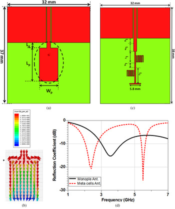
The structure of the monopole patch is shown in Fig. 1(a). The monopole is fed by a 50 Ω CPW TL with center line width = 1.5 mm, gap = 0.25 mm, and length = 15 mm. The patch length is 13.5 mm, this is quarter wavelength at designed middle frequency (3.6 GHz). The patch width is 6.5 mm, which was proved being wide enough for good antenna radiation. The simulated antenna reflection coefficient, shown in Fig. 1(d), indicates that the monopole patch can operate at frequencies from 3 to 4.2 GHz mid frequency band (3.3–3.8 GHz). The surface current distribution at 3.6 GHz is illustrated in Fig. 1(b). It shows that the surface current is weaker in the middle and open end parts of the patch, i.e. the radiation was mainly contributed by the two edges. Thus, one may utilize the rest parts of the patch to generate extra resonances at other frequencies, which will not cause much distortion to the existing one. It is also worth of notice that the edge close to the feed line does not contribute to radiation either because of the opposite current flow as noted from Fig. 1(b).
The mid band monopole antenna to cover 3.3–3.8 GHz band: (a) the layout, (b) the current distributions at 3.6 GHz for 90° phase snapshot, (c) the geometry of the two-cells half mode CRLH TL loaded antenna, where L g + L fe = 3 mm, L 1 = 6 mm, L 2 = 6 mm, and L 0 = 2 mm, (d) the simulated reflection coefficient of the monopole patch (black solid line) and meta-material monopole antenna loaded with two-cells half mode CRLH TL (red dash line).

C) Half mode CRLH cell antenna
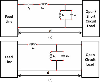
In this section, we explain the mechanism of the half mode CRLH cell antenna. The idea of the half mode CRLH cell for antenna applications has been presented in [Reference Abdalla and Hu52, Reference Abdalla, Fouad, Ahmed and Hu53]. The equivalent circuits of a lossless CRLH cell are shown in Fig. 2(a). The CRLH cell is formed by loading a TL with series capacitor (C L ) and shunt inductor (L L ) in addition to the TL parasitic capacitor (C R ) and inductor (L R ). By loading the CRLH TL, a compact CRLH antenna can be realized. It has been shown in [Reference Rennings, Liebig, Caloz and Waldow56] that the open circuit resonance mode of the zeroth-order mode CRLH antenna is thanks to the shunt branch resonance. On the other hand, the series branch resonance is the corresponding to short circuit loading. The resonance frequencies for the shunt branch (f 0sh ) and the series branches (f 0se ) can be written as
 $${f_{0sh}} = \displaystyle{1 \over {2\pi \sqrt {{L_L}{C_R}}}}, $$
 $${f_{0se}} = \displaystyle{1 \over {2\pi \sqrt {{L_R}{C_L}}}}. $$
The equivalent circuit model of the CRLH TL antenna: (a) the full mode case, (b) the practical half mode.

It has been shown in [Reference Abdalla and Hu52, Reference Abdalla, Fouad, Ahmed and Hu53] that a simpler and ultra compact meta-material antenna is possible by using only open-circuited half mode CRLH cell. In other words, the half mode cell is suggested to be realized using the shunt combination only (C R and L L ) as shown in Fig. 2(b), where the element L R corresponding to the parasitic inductance, cannot be avoided in practical realization.
In our work, the design for the proposed antenna will be based on the shunt loading of CRLH in open circuit termination. The design for the employed elements (L L and C R ) will be extracted by adjusting the desired frequency f 0sh in (1) to the required frequency.
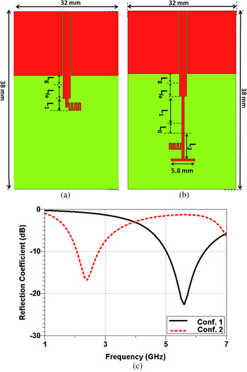
To illustrate the claimed half mode based antenna operating principle, two different CPW fed configurations for single cell half mode CRLH resonator antennas have been studied to operate at 5.5 and 2.4 GHz as illustrated in Figs 3(a) and 3(b), respectively. In both cases, the half mode CRLH cells are formed by a strip inductor and closed parallel lines capacitor. In Fig. 3(a), the inductor is a strip of length of L 1 whereas in Fig. 3(b), it is formed by T shaped strip. In both cases, the strip inductor is connected to seven closed parallel lines capacitor. The line width and separation are 0.2 mm and length 1.5 mm. It is obvious that the employed elements are connected so that the current will be divided, in shunt configuration, which satisfies the equivalent circuit in Fig. 2(b).
The geometry of the one cell half mode CRLH TL loaded antenna, where L g + L fe = 3 mm: (a) conf. 1, L 1 = 3 mm (b) conf. 2, L 1 + L 2 + L 0 = 12 mm, (c) the simulated reflection coefficients for the single cell half mode CRLH antenna (conf. 1 is (a), conf. 2 is (b)).

It is worth to comment that the optimization between the cell size and the resonant frequency will limit the design of C R and L L to match the monopole size. Accordingly, the dimensions were selected to satisfy (1) at the two design frequencies. The electrical values for half mode CRLH cell elements can be calculated as in [Reference Hong57]. It is worth to comment that the idea of designing these two half mode CRLH cells configuration is to load the patch by their complementary version, the closed parallel lines capacitor will become an interdigital capacitor and strip will become a slot, which will be explained later. Therefore, the suggested configuration yields compact meta-material antenna resonators at different locations on the patch that will be used to achieve lower resonance to cover the 2.5–2.7 GHz band and higher one for 5.3–5.9 GHz band.
The simulated reflection coefficients for the two half mode configurations antennas are shown in Fig. 3. As shown in the figure, the antennas in Figs 3(a) and 3(b), resonates at 5.5 and 2.5 GHz, respectively. The shift in the frequency is due to the higher value of the inductor in Fig. 3(b) as can be predicted from (1). Next the two half mode CRLH -cells antenna is studied, as shown in Fig. 1(c). The structure comprises T shaped strip loaded with two open ended meandered line capacitor. The dimensions of the two cell configuration are almost the same as given in Fig. 3 with slight variation for matching enhancement at the operating frequencies. The simulated reflection coefficient of the two half mode CRLH cells antenna is shown in Fig. 1(d). It becomes clear that the antenna has better than −10 dB reflection coefficient at two desired bands
D) Integrated monopole and complementary half mode CRLH cell antenna
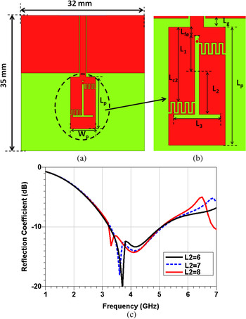
The triple band antenna is based on the integration of the aforementioned two antennas (the monopole patch and the complimentary half mode CRLH cell antenna). In particular, the meta-material half mode CRLH cell is subtracted from the monopole patch. The resultant antenna layout is shown in Fig. 4. Now, each complementary half mode cell is constructed using an interdigital capacitor and a short slot. The slot is of a T shape so to make the overall antenna compact. Here the interdigital capacitors have four fingers with gaps of 0.2 mm, and finger length of 1.2 mm. Further analysis of the structure, however, reveals that the antenna in Fig. 4(c) does not provide triple band radiation. As it can be seen in Fig. 4, this layout actually has only a single resonance within the spectrum of interests.
(a) The layout of the integrated monopole patch with half mode CRLH cells, (b) the simulated reflection coefficients of the integrated monopole antenna with half-mode CRLH TL cells for different slot lengths.

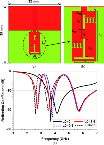
To introduce extra resonances, we have shorted the slot at middle because there is a need of extra path for surface current to generate extra resonances. The modified antenna layout is shown in Fig. 5 where the two complementary half mode CRLH cells are separated with distance L 0. This allows controlling the resonant frequency for each cell independently. The electromagnetic full wave simulation results of the modified antenna are shown in Fig. 5(c). It is clear that the antenna, except for the case L 0 = 0, demonstrates triple band behaviors centered approximately around 2.6, 3.6, and 5.8 GHz, respectively with relatively small effects of non-zero L 0.
(a) The layout of the triple band meta-material half mode CRLH loaded monopole antenna, (b) the simulated reflection coefficients of the meta-material half mode CRLH TL loaded triple band antenna for different length of L 0.

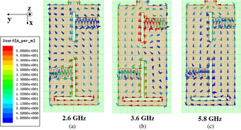
To better understand the mechanism for inducing extra resonances, the surface current distribution is illustrated in Fig. 6. It becomes clear that the two half mode CRLH cells loading have forced the majority surface current in phase along the monopole in the x-axis at the resonant frequencies so to enable the monopole mode radiations.
The current distribution of the triple band meta-material half mode CRLH loaded antenna at (a) 2.6 GHz, (b) 3.6 GHz, and (c) 5.8 GHz.

E) Antenna measurements
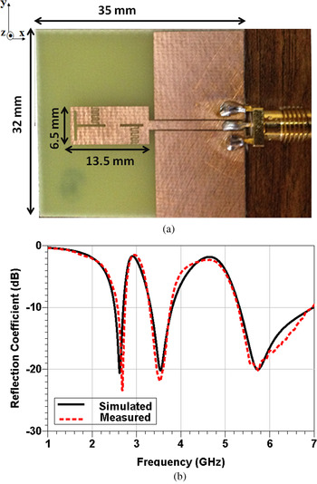
The fabricated triple band meta-material half mode CRLH TL loaded antenna is shown in Fig. 7(a). To illustrate the antenna design compactness, we have compared the final designed radiator patch (13.5 × 6.5 mm2) to conventional single band microstrip patch antenna. For the same feeding TL length (20 mm), the single patch size is 36.5 × 28.5 mm2 at 2.5 GHz, with overall antenna of 80 × 64 mm2, with overall antenna size = 62 × 49 mm2, at 3.5 GHz and 16.6 × 14.4 mm2 at 5.5 GHz, with overall antenna size = 46 × 34 mm2. From this comparison, we can claim that the novel triple band radiator size has been reduced by 91% and the whole antenna by 75% at 2.5 GHz, 83 and 48% at 3.5 GHz and 47 and 18% at 5.5 GHz.
A photograph of the fabricated triple band meta-material half-mode CRLH cell loaded monopole antenna, (b) simulated and measured reflection coefficients of the triple band meta-material half-mode CRLH cell loaded monopole.

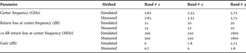
The electromagnetic full wave simulation and measured reflection coefficients of the triple band meta-material antenna are given in Fig. 7(b). The measured first operating band is centered at 2.6 GHz with −10 dB bandwidth extending from 2.5 to 2.7 GHz. Similarly, the second operating band is centered at 3.6 GHz and extends from 3.3 to 3.8 GHz. The third band is centered at 5.8 GHz and extends from 5.3 GHz to almost 7 GHz. The figure illustrates very good agreement between the measured and the simulated results, demonstrating that the novel meta-material monopole antenna suits very well for multiband WiMAX applications. These results validate the antenna aforementioned design procedures.
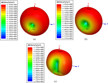
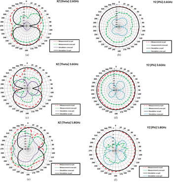
The antenna radiation performance at the three operating bands has also been investigated by examining the radiation patterns at center frequencies of the operating bands both numerically and experimentally. The 3D simulated radiation pattern at 2.6 GHz is depicted in Fig. 8(a), clearly showing a typical omnidirectional pattern (doughnut-like). The simulated gain is about 0 dBi and radiation efficiency 0.868. The simulated and measured co- and cross-polarization radiation patterns in the E-plane (XZ-plane, ϕ = 00) and H-plane (YZ-plane, ϕ = 900) are depicted in Figs 9(a) and 9(b), respectively. As it can be seen, the simulated (solid black line) and measured (dash red line) co-polarizations in E-plane show good agreement. Both demonstrate typical eight-like shape radiation patterns due to x-direction linear electric field polarization. This is consistent with the surface current along the x-axis in Fig. 9(a). The measured gain is about 0.7 dBi, polarizations are apart. The cross-polarization was mainly caused by slightly higher than the simulated one of 0 dBi. On the other hand, the simulated (solid purple line) and measured (dash green line) cross- y-directed current induced by the half mode CRLH cell close to the open end of the patch as shown in Fig. 6(a), resulting relatively higher cross-polarization in the −x-direction, i.e. in the right-half of Fig. 9(a). The much larger measured cross-polarization is likely caused by the interference of unbalanced current occurring on the two CPW ground planes due to the lack of air-bridge connecting them.
The 3D radiation pattern: (a) at 2.6 GHz, (b) at 3.6 GHz, (c) at 5.8 GHz.

Comparison between the simulated and measured co- and cross-polarization radiation patterns (a), (b) at 2.6 GHz in: (a) E-plane (XZ-plane, ϕ = 0o) and (b) H-plane (YZ-plane, ϕ = 90o); (c), (d) at 3.6 GHz in (c) E-plane (XZ-plane, ϕ = 0o) and (d) H-plane (YZ-plane, ϕ = 90o); (d), (e), (f) at 5.8 GHz in (e) E-plane (XZ-plane, ϕ = 0o) and (f) H-plane (YZ-plane, ϕ = 90o).

In the H-plane, both simulated and measured co-polarization patterns are omnidirectional and agree very well. The 3D simulated radiation pattern at 3.6 GHz is plotted in Fig. 8(b). As we can observe the antenna preserves the typical omnidirectional shape and it is close to that pattern at first operating band (2.6 GHz) shown earlier in Fig. 8(a). As shown, the simulated gain is 1.58 dBi. The simulated radiation efficiency is 0.895. The simulated and measured co- and cross-polarizations in E-plane (XZ-plane, ϕ = 00) and H-plane (YZ-plane, ϕ = 900) are shown in Figs 9(c) and 9(d), respectively. The simulated and measured co-polarization radiation patterns are largely in good agreement. The discrepancies mainly in the + x-direction, i.e. in the left-half of Fig. 9(c), probably again caused by the un-balanced CPW ground planes. It is interesting to see that the cross-polarized E-field has a dipole mode. This is attributed from the stronger in-phase surface currents along the edge of the monopole close to the CPW feed line than the opposite surface current along the edge of the open end, as shown in Fig. 6(b), which results in higher cross-polarization in the + x-direction. In the H-plane, the simulated and measured co-polarized H-field patterns are in good agreement. The measured gain at 3.6 GHz is 0 dBi, lower than the simulated one of 1.6 dBi.
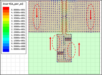
At 5.8 GHz, the 3D simulated gain pattern is plotted in Fig. 8(c). It can be observed at higher frequency band the radiation pattern become less doughnut-like on + x-direction. The cause of this can be observed from Fig. 10, showing the two CPW ground planes also radiate. However, the x-directed surface current on the two CPW ground planes is opposite to the x-directed surface current on the patch, resulting in less gain on the +x-direction. This can also be clearly seen in Fig. 9(e). The simulated gain is 2.729 dB and radiation efficiency is 0.905. In Fig. 9(f), it can be seen that the simulated and measured co-polarized H-fields are in good agreement. The measured gain is 1.6 dBi, lower that the simulated one of 2.73 dBi.
The surface current distribution at 5.8 GHz.

Based on the previous results, we can claim that the small discrepancies between measured and simulated results were mainly due to the effect of the non-avoided reflections during measurements such as the reflection from the SMA connector whose size is comparable with the radiator size.
Also, it is worth to explain that the measured gain procedure was done based on the three antenna method. This method was used based on the single antenna under test in addition to two different antennas (operating at the same bandwidth). The method is based on measuring the received power from transmitting one using each pair of the three antennas, which is calculated as
 $${G_{i{\rm dB}}} + {G_{j{\rm dB}}} = 20\log \left( {\displaystyle{{4\pi R} \over \lambda}} \right) + 10\log \,{\left( {\displaystyle{{{P _r}} \over {{P_t}}}} \right)^{(k)}},$$
where i and j referes to the two different antennas (antenna # i and antenna # j) measured during experiment #k (k = 1, 2,3). The measurement was done at a fixed distance (enough to satisfy the far field criterion) between transmitting and receiving antennas. Thus, this method allows the calculation of the three antenna gains. More details about the method can be found in [Reference Balanis58].
In summary, the performance of the proposed triple band antenna is tabulated in Table 1.
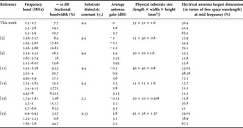
A comparison between introduced antenna in this paper and recent previous work.

Finally, a comparison between the proposed antenna and recent triple band compact size antenna are summarized in Table 2. The comparison demonstrates competitive features for the proposed antenna in terms of its compact size, good gain. Also, it is worth to comment that the proposed antenna has suitable bandwidth for wireless services, which is neither too large to suffer interference nor too narrow to affect the service.
A comparison between triple band antennas (recent published and the proposed antenna in this paper).

II. CONCLUSION
The technique for designing multiband antennas based on loading the monopole antenna with simplified half mode CRLH cells has been proposed. A case study for triple band antenna has been experimentally demonstrated. The antenna has been designed to cover three bands (2.5–2.7 band, 3.3–3.8 band, and 5.3–5.9 GHz band) based on the proposed technique. The monopole patch itself introduces middle resonance whereas the two-cell CRLH TL loading provides extra two resonances at lower and upper frequency bands. The fabricated antenna has a size of 35 × 32 mm. The antenna's radiation patterns further validate the design both numerically and experimentally, showing that simulated and measured E- and H-fields are largely in a good agreement. Good radiation efficiency and antenna gain have been achieved at all three bands.
 Mahmoud Abdelrahman Abdalla was born in 1973, received the B.Sc. degree, with grade of excellent with honors, in Electrical Engineering from the Electronic Engineering Department, Military Technical College, Cairo, Egypt in 1995. He was awarded the M.Sc. degree in Electrical Engineering from Military Technical College in 2000, and the Ph.D. degree from Microwave and Communication group, School of Electrical Engineering, Manchester University, UK, in 2009.
He has been with Military Technical College since 1996 where he is now an Associate Professor in Electronic Engineering Department. His research has focused on different metamaterial applications in microwave and millimeter bands specially microwave components, miniaturized multiband antennas, and ferrite components. Also his research includes electromagnetic energy harvesting systems, EBG components, adaptive antenna systems for DOA estimation and interference cancellations, and radar absorber designs. He has published about 100 peer-reviewed journal and conference papers. Dr. Mahmoud Abdalla is a senior member of the IEEE and the European Microwave Association EuMA. He is currently a reviewer in many electromagnetic journals such as IEEE Antennas and Wireless Propagation Letters, IEEE transaction in Magnetics, IET Microwave, antenna and propagation, International Journal of Microwave and Wireless Technologies, Journal of electromagnetic waves (JEMW), Progress in Electromagnetic Research, European Physical Journal – Applied Physics, Journal of Applied Computational Electromagnetic Society, Advanced Electromagnetic and some others.
 Zhirun Hu (M'98) received his B.Eng in Communication Engineering from Nanjing, China, in 1982, Master in Business Administration, and Ph.D. in Electrical and Electronic engineering from the Queen's University of Belfast, United Kingdom, in 1988 and 1991, respectively.
In 1991, he joined the Department of Electrical and Electronic Engineering, University College of Swansea, as a senior research assistant in computational semiconductor device simulation. In 1994, he was with the Department of Electrical and Electronic Engineering, the Queen's University of Belfast, as a research fellow in silicon MMIC design, realization and characterization. In 1996, he joined GEC Marconi, as a microwave technologist working on microwave/millimetre-wave device and circuit design and characterization. He was a lecturer with the Department of Electronic Engineering, King's College London from 1998 to 2003. He is now with the School of Electrical and Electronic Engineering, the University of Manchester. He has published more than 200 peer-reviewed journal and conference papers.
 Cahyo Muvianto received all degree in Electrical and Electronic Engineering, Bachelor from the ITS, Surabaya, Indonesia, in 1995, M.Sc. degree From University of Manchester Institute of Science and Technology (UMIST), and Ph.D. degree from The University of Manchester, Manchester – UK, in 2001 and 2012, respectively. From 1995 to 2000, he worked at radio paging company as chief of engineer and later as operation manager in Mataram-Indonesia. He joined the Department of Electrical Engineering, University of Mataram- Indonesia as lecturer in 1998. He is currently as Research Associate with the School of Electrical and Electrical Engineering, The Manchester University. His research work is focused on microwave sensors and applications systems.