Introduction
Textile dyeing wastewater is a great part of industrial effluent due to the organic dyes that cause serious environmental problems for many years [Reference Chowdhury and Saha1]. To date, many technologies, like chemical treatment [Reference Hayat, Mahmood, Pervez, Bhatti and Baig2], conventional coagulation [Reference Liang, Sun, Li, Ong and Chung3], ion exchange [Reference Labanda, Sabate and Llorens4], electrodialysis [Reference Ramirez, Javier Recio, Herrasti, Ponce-de-Leon and Sires5], adsorption [Reference Hu, Fang, Wang, Liu, Zhu and Zhu6], and photocatalytic degradation, for treating printing and dyeing wastewater have been proposed [Reference Wang, Wang, Yu, Huang, Fang, Long, Song, Cifuentes, Humphrey, Zhang, Shao and Zhang7]. Among them, photocatalytic degradation has the advantages, such as clean solar energy, low cost semiconductor, high activity, and no secondary pollution [Reference Li, Xie, Jiang, Yu and Zhang8, Reference Liu, Wang, Ma and Zhang9]. Photocatalytic materials are generally divided into light response and ultraviolet light response due to their different response mechanisms. As ultraviolet (UV) radiation accounts for only about 3–5% of the incident energy of sunlight [Reference Pham, Nguyen-Huy and Shin10], the visible light photocatalytic degradation has obvious features of available operation and easy large-scale degradation [Reference Liu, Chen, Xu, Zhang and Shen11, Reference Wang, Fang, Tang, Zhang, Huang, Liu and Wu12]. Thus, an effective visible light photocatalytic degradation material has a great potential in the wastewater treatment.
Titanium dioxide (TiO2) nanomaterial is a typical n-type semiconductor material; has the properties of high photoactivity, non-toxicity, and good chemical and thermal stability; and have been extensively researched since Fujishima et al. and others used TiO2 electrodes as photocatalysts for splitting water molecules [Reference Liu, Wang, Ma and Zhang9, Reference Yu, Liu, Wang and Wang13, Reference Fujishima and Honda14, Reference Liu and Zhang15, Reference Wen, Li, Liu, Fang, Xie and Xu16, Reference Savinkina, Obolenskaya, Kuzmicheva, Morozov and Chumakov17]. It is found that pure TiO2 generally exhibits limited photocatalytic activity due to its relatively wide band gap (∼3.2 eV) and the rapid recombination of photogenerated electrons and holes in the bulk or on its surface [Reference Wen, Li, Liu, Fang, Xie and Xu16, Reference Abid, Bouattour, Ferraria, Conceicao, Carapeto, Vieira Ferreira, Botelho do Rego, Rei Vilar and Boufi18, Reference Pan, Shen, Jin and Zhu19, Reference Zhang, Wang, Liu and Li20]. To improve the photocatalytic behavior of TiO2 photocatalysts, various strategies have been widely developed by designing and modifying various TiO2-based composites. At present, the methods of catalytic degradation under visible light can be summarized as follows: noble metal doping [Reference Yang, Yan, Wang, Wen, Wang, Fan, Shi and Li21, Reference Zhang, Miao, Hu, Mu, Liu, Han, Fan, Liu, Yin and Wan22, Reference Chen, An, Li, Liang and Cui23, Reference Liu, Yan, Chen, Tian, Xia and Chen24], transition metal doping [Reference Li, Song, Wei, Zhang, Qin and Ye25, Reference Xu and Xu26, Reference Wada, Yokomizo, Yogi, Katayama, Tanaka, Kojima, Inada and Ozutsumi27], non-metallic doping [Reference Komatsuda, Asakura, Vequizo, Yamakata and Yin28, Reference Mishra, Parida and Singh29, Reference Jing, Cheng, Weller, Chu, Wang and Chan30, Reference Song, Li and Wang31], co-doping [Reference Huang, Ho, Ai, Song, Zhang and Lee32, Reference Zou, Feng, Ganeshraja, Xiong and Yang33], and organometallic frames and polymer composites to form complexes [Reference Pelaez, Nolan, Pillai, Seery, Falaras, Kontos, Dunlop, Hamilton, Byrne, O’Shea, Entezari and Dionysiou34]. TiO2 with metal doping can effectively inhibit electron–hole recombination, thereby improving the photocatalytic effect [Reference Yang, Gao, Wang, Liu and Hu35]. Specifically, the metal has a lower Fermi level relative to TiO2, and photoexcited electrons can be transferred from the TiO2 conduction band (CB) to the surface of the metal particles, while positive holes are contained in the valence band (VB) [Reference Pham, Nguyen-Huy and Shin10]. It has been found that TiO2 and metal doping can obtain the visible light catalytic degradation effect. For example, metallic nickel is an excellent candidate due to its high availability, low cost, and good durability [Reference Pham, Nguyen-Huy and Shin10]. Rodríguez-González et al. prepared the Ni-TiO2 doped photocatalyst (0.5–6 wt% Ni) by a simple sol–gel method to degrade the alizarin red S (ARS) dye under UV black light irradiation (λ = 365 nm). It was found that Ni-TiO2 doped photocatalyst is more active in the photodegradation of ARS than P25 commercial TiO2 [Reference Rodríguez-González, Ruiz-Gomez, Torres-Martinez and Gomez36]. Li et al. prepared a novel nickel-doped titania inverse opal photonic chip, which was used as a photocatalyst to degrade methylene blue (MB) by 90% in 90 min [Reference Li, Wu, Shen, Sun, Yang and Xie37].
However, the problem of how to firmly immobilize photocatalysts on substrate has greatly limited their application, since methods are generally dipping or coating so far, and the composite fabric prepared by these methods has poor hand feeling and low loading fastness. In this regard, to realize material with all-in-one structure is practical when in use. Hence, we proposed to use polymer material polyaniline (PANI) as a media, which has the reducing ability to noble catalyst and can initiate electroless plating. Furthermore, the combination of PANI and TiO2 also has a positive effect on photocatalytic activity due to its potential synergistic effect [Reference Akti38, Reference Yan, Chen, Zou and Wang39]. Some studies has demonstrated that under visible light irradiation, PANI generates a π–π* transition, which transfers the excited electrons into the CB of TiO2, and the electrons are transferred to additional electron acceptors to generate oxygenated free radicals to degrade the pollutants [Reference Hao, Ruilong, Jincai and Yongfa40]. According to above-mentioned mechanism, we can speculate this method can successfully prepare all-in-one structure photocatalytic degradation material with good degradation ability.
There are many TiO2/PANI and TiO2/Ni photocatalytic systems reported in recent articles; for instance, Li et al. prepared PANI/TiO2 composites by in situ polymerization and chemical adsorption methods [Reference Li, Zhang and Li41] and Rodríguez-González et al. prepared the Ni-TiO2 doped photocatalyst [Reference Rodríguez-González, Ruiz-Gomez, Torres-Martinez and Gomez36]. But the synergistic effect of nano-TiO2, Ni, and PANI to improve the photocatalytic ability of the system has not been reported. Herein, a high-performance polyimide (PI) fabric is selected as a substrate, which has high strength and excellent corrosion resistance when used in wastewater, and then the aniline monomer is polymerized in situ on the PI fabric to form PANI. Finally, the nickel–phosphorus plating–titanium dioxide (Ni-P-TiO2) layer is immobilized on the above-prepared fabric as shown in Fig. 1. The most important thing is that TiO2 is firmly embedded in the Ni-P layer to meet repeated reuse. The features of Ni-P-TiO2/PANI/PI fabric were characterized by scanning electron microscopy (SEM), energy-dispersive spectroscopy (EDS), X-ray photoelectron spectroscopy (XPS), and X-ray diffraction (XRD). The thermal stability of the sample was also evaluated by thermogravimetric analysis (TGA). The photocatalytic efficiency and recyclability by degrading reactive blue 19 (RB-19), MB, and reactive red (M-3BE) under visible light were systematically analyzed.
Preparation of Ni-P-TiO2/PANI/PI fabric.

Results and discussion
SEM analysis
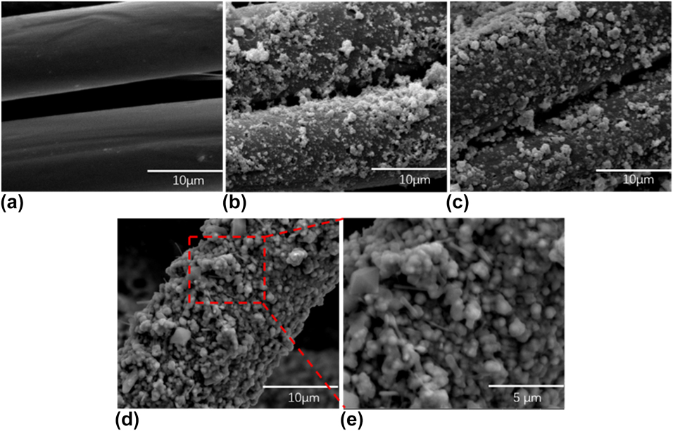
The morphology of the samples at different stages was observed by SEM. The SEM images of PI fabric, PANI/PI fabric, PdCl2 reduced PANI/PI fabric, and Ni-P-TiO2/PANI/PI fabric are shown in Figs. 2(a)–(e), respectively. As shown in Fig. 2(a), the pretreated PI fabric displayed obvious grooves, and the increase in roughness provided a larger contact area for the subsequent aniline, thereby increasing the adhesion fastness. The PI fabric was uniformly covered in Fig. 2(b) due to PANI in situ polymerization. In Fig. 2(c), a small amount of white metal particles appear, which is due to the reduction of Pd2+ to Pd0 by PANI, and they are activated seeds to initiate electroless plating. It can be seen from Figs. 2(d) and 2(e) that TiO2 nanoparticles are uniformly embedded in the Ni-P layer, which indicates that the Ni-P-TiO2/PANI/PI fabric was successfully prepared.
Typical SEM images of (a) PI fabric, (b) PANI/PI fabric, (c) PdCl2 reduced PANI/PI fabric, and (d and e) Ni-P-TiO2/PANI/PI fabric.

EDS analysis
The EDS patterns and element mappings were used to measure the element type of the PI fabric, PANI/PI fabric, PdCl2 reduced PANI/PI fabric, and Ni-P-TiO2/PANI/PI fabric samples [Figs. 3(a)–3(d)]. Comparing Fig. 3(a) with Fig. 3(b), the mass ratio and the atomic ratio of the C and N elements increased slightly; on the contrary, the O element decreased slightly, which fully proved that the PANI layer was successfully coated on the PI fiber. It can be seen from Fig. 3(c) that the appearance of palladium element was attributed to the reduced palladium particles, which were the catalytic seeds that initiated the composite electroless plating. As can be seen from Fig. 3(d), a strong nickel signal is shown, which has a mass content of 74.11% after chemical treatment and a titanium content of 0.64%. Here, the Ni-P layer was equivalent to the “solvent,” TiO2 nanoparticles were equivalent to the “solute,” and the TiO2 nanoparticles were evenly distributed in the Ni-P layer. In addition, the mass fraction of the C and O elements was relatively decreased, indicating that the fiber was sufficiently covered by the Ni-P-TiO2 layer.
EDS spectra of (a) PI fabric, (b) PANI/PI fabric, (c) PdCl2 reduced PANI/PI fabric, and (d) Ni-P-TiO2/PANI/PI fabric.

XPS analysis
To further investigate the composite electroless Ni-P-TiO2 plating on the PI fabric in situ polymerization of aniline, XPS analysis was carried out, as shown in Fig. 4. The XPS spectra of PI fabric, PANI/PI fabric, PdCl2 reduced PANI/PI fabric, and Ni-P-TiO2/PANI/PI fabric are shown in Figs. 4(a), 4(d), 4(g), and 4(j), respectively. It can be seen that the peak of the N element is significantly enhanced by comparing Figs. 4(a) and 4(d). In addition, the data indicate that the atomic ratio of N element increases from 2.49% to 6%. Moreover, N 1s core-level spectrum of PANI/PI fabric with three decomposed peaks is shown in Fig. 4(f), the fitted peaks at 399.2 eV, 399.8 eV, and 400.9 eV belong to benzenoid diamine nitrogen (–NH–), quinoid diimine (–N=), and positively charged nitrogen (N+), respectively [Reference Jiang, Syed, Gao, Lu and Meng42, Reference Qiu, Han, Qiu and Yang43]. As shown in Fig. 4(h), the Pd 3d spectrum shows two main peaks appeared at 341.3 eV and 335.9 eV correspond to Pd 3d 3/2 and Pd 3d 5/2, respectively. It can be concluded that the Pd species were mainly existed as metallic Pd (Pd0) [Reference Wu, Zhang, Long, Qin, Wen and Ma44, Reference Chen, Liu, Guo, Chen and Gao45]. The high-resolution P 2p spectrum at around 133.1 eV was corresponded to the elemental substance of phosphorus. The Ni 2p spectrum showed a 2p 1/2 peak at around 873.3 eV and an Ni 2p 3/2 peak at around 856.0 eV [Reference Wu, Zhang, Long, Qin, Wen and Ma44]. It can be noted that signals corresponding to Ti 2p 3/2 and Ti 2p 1/2 were observed at the binding energies 458.5 and 464.0 eV, respectively, which proved that the valence state of the titanium ions was +4, indicating that the TiO2 was successfully immobilized on the metal layer after electroless plating [Reference Xu, Yang, Johansson, Wang and Jin46]. These results are consistent with those of the SEM and XRD characterization.
XPS spectra and core-level spectra of (a–c) PI fabric, (d–f) PANI/PI fabric, (g and h) PdCl2 reduced PANI/PI fabric, and (i–l) Ni-P-TiO2/PANI/PI fabric.

XRD analysis
The crystalline structures of PI fabric, PANI/PI fabric, PdCl2 reduced PANI/PI fabric, and Ni-P-TiO2/PANI/PI fabric were ascertained by XRD. As shown in Figs. 5(a) and 5(b), it can be clearly seen that PANI attached to the surface of PI fibers has no significant effect on the crystal structure of PI fiber macromolecules. However, the degree of crystallinity decreases after PANI reduces Pd ions, as shown in Fig. 5(c). It can be seen from Fig. 5(d) that two diffraction peaks appear: the diffraction peak at 2θ = 45.3 was the reflection of nanocrystalline Ni(111), which corresponded to Ni(111) of the face-centered cubic (FCC) crystalline phase according to the JCPDS 04-0850 [Reference Bahgat Radwan, Ali, Shakoor, Mohammed, Alsalama, Kahraman, Yusuf, Abdullah, Fatima Montemor and Helal47], and the diffraction peak at 2θ = 25.7 was the reflection of TiO2 nanoparticles, which corresponded to TiO2(101) planes according to the JCPDS 21-1272 [Reference Cao, Wang, Ao, Wang, Hou and Qian48]. In addition, the diffraction peak of the PI fabric after electroless plating almost disappeared, which was attributed to the uniform and compact Ni-P-TiO2 layer on the PI fabric.
XRD patterns of (a) PI fabric, (b) PANI/PI fabric, (c) PdCl2 reduced PANI/PI fabric, and (d) Ni-P-TiO2/PANI/PI fabric. (e) Enlarged view of (d).

TGA analysis
These samples were tested at N2 atmosphere with a heating rate of 10 °C/min and the temperature was ranged from 30 to 900 °C. As shown in Figs. 6(a)–6(c), the first decomposition reaction of the three samples occurred at 146–198 °C, and the mass percentage decline of PI fabric (a) was more obvious than that of PANI/PI fabric (b) and Ni-P-TiO2/PANI/PI fabric, which was due to the decomposition of impurities and oligomers within this temperature range. Similarly, the second decomposition of these samples started at 560 °C, and the sample mass percentage decreased sharply with increasing temperature due to degradation of the macromolecular chains of the PI fibers. The residual components of three samples at 900 °C were 33.7%, 37.0%, and 56.6%, respectively. It could be deduced from the results that the content of Ni-P-TiO2/PANI/PI plating was about 31.1%. The result was basically consistent with the weight increasing value of 32.4%, calculated according to Eq. (3).
TGA curves of (a) PI fabric, (b) PANI/PI fabric, and (c) Ni-P-TiO2/PANI/PI fabric.

Ultraviolet–visible analysis and N2 adsorption–desorption of samples
The optical absorptions of the samples were measured by ultraviolet–visible (UV-vis) diffuse reflectance spectroscopy (DRS), as shown in Fig. 7. It is apparent that the original PI fabric (a) [Fig. 7(A)] has no significant absorption in the visible light region, indicating that the original PI fabric has no visible light absorption capacity. In contrast, the Ni-P-TiO2/PANI/PI fabric (b) exhibits a large absorption capacity in the UV-vis region in Fig. 7(A), which can be attributed to the synergistic effect. On the one hand, the presence of PANI and nickel reduces the energy gap spacing of the photocatalyst titanium dioxide, and on the other hand, it accelerates the separation of electrons and holes. There is no doubt that the band structure of semiconductors plays an important role in photocatalytic efficiency. Based on the UV-vis results, the band structure of the Ni-P-TiO2/PANI/PI fabric was calculated as follows:
 $$Ahv = C{\left( {hv - {E_{\rm{g}}}} \right)^{n/2}}\quad ,$$
where A, h, v, C, and E g represent the a constant, Planck’s constant, incident light frequency, the absorption coefficient, and the band gap energy, respectively. Figure 7(B) shows the curve between (Ahv) and photon energy (hv) of Ni-P-TiO2/PANI/PI fabric. For TiO2, the value of n is 1. The band gap of Ni-P-TiO2/PANI/PI fabric is 2.68 eV, which is lower than the gap spacing of pure TiO2 (3.2 eV).
(A) UV-vis DRS of original PI fabric (a) and Ni-P-TiO2/PANI/PI fabric (b). (B) The curve between (Ahv)2 and photon energy (hv) of the Ni-P-TiO2/PANI/PI fabric. (C) The N2 adsorption–desorption isotherms and (D) pore size distributions of the samples.

The Brunner-Emmet-Teller measurements (BET) surface area and pore distribution of the TiO2 sample were obtained by BET and Barret-Joyner-Halenda theory (BJH) analysis. The N2 adsorption–desorption isotherms and pore size distributions of the samples, respectively, are shown in Figs. 7(C) and 7(D). Figure 7(C) shows one hysteresis loop at a relative pressure ranging from 0.8 to 1, indicating that the TiO2 has a mesoporous structure. The pore distribution curve in Fig. 7(D) shows that the average pore diameter of TiO2 is 27 nm.
Photocatalytic performance
The photocatalytic performance of the Ni-P-TiO2/PANI/PI fabric was evaluated by degrading the MB under visible light irradiation. Figure 8(A) demonstrates the degradation ratios of MB for PI fabric (a) and Ni-P-TiO2/PANI/PI fabric (b). It is worth noting that the adsorption–desorption equilibrium was achieved for 30 min under dark conditions before visible light irradiation. It can be clearly seen that the composite fabric had a weak adsorption effect on the dye in the dye liquor, so the color fading of the dye liquor was mainly attributed to the degradation of the dye by the photocatalyst. The dyeing solution containing PI fabric did not change significantly with the increase in illumination time. Conversely, the dye liquor decomposes rapidly in the presence of a photocatalyst, the color fades accordingly and the absorbance decreases. The degradation rate of the dye solution as high as 96.4% for Ni-P-TiO2/PANI/PI system was observed under visible light irradiation for 2.5 h, while for the comparative PI, it was only 7.8%. To further investigate the kinetics of MB degradation, a pseudo-first-order model was used, which can be expressed as follows:
 $$\ln {{{C_0}} \over {{C_t}}} = {K_{{\rm{app}}}}t\quad ,$$
where K app is the pseudo-first-order rate constant and C 0 and C t are the initial concentration of MB and the concentration of MB at irradiation time t, respectively. As shown in Fig. 8(B), the K app of Ni-P-TiO2/PANI/PI was 0.0199 min−1 (b), which is almost 35 times higher than that of PI sample (a) (K app = 0.000573).
(A) Photocatalytic degradation of MB by PI and Ni-P-TiO2/PANI/PI fabric under visible light irradiation. (B) Kinetic curves of ln(C 0/C t) versus reaction time for photodegradation of MB. (C) Photocatalytic degradation of different dye by Ni-P-TiO2/PANI/PI fabric under visible light irradiation. (D) Kinetic curves of ln(C 0/C t) versus reaction time for photodegradation of MB. The illustrations in (B) and (D) are digital photos before and after degradation of the dye solution.

To better display the excellent photocatalytic performance of composite fabrics, a variety of dyes were selected for visible light catalytic degradation, including RB-19, MB, and reactive red (M-3BE), as shown in Fig. 8(C). Similarly, the composite fabric was adsorbed in three dyes for 30 min before visible light irradiation, which further proves that the adsorption of the dye on the composite fabric is negligible. After 2.5 h of irradiation under visible light, the composite fabric exhibited excellent photocatalytic properties for all three dyes. The degradation rates of MB, reactive red, and reduced blue were 96.4% (a), 92.6% (b), 91.6% (c), respectively, and K app were 0.0199 min−1 (a), 0.0174 min−1 (b), 0.0175 min−1 (c), respectively [Fig. 8(D)].
Recycle performance of Ni-P-TiO2/PANI/PI composite for dye degradation
The stability and recyclability of the Ni-P-TiO2/PANI/PI fabric were evaluated by five cycles of use. As depicted in Fig. 9, as the cycle number increases, the degradation rate of the composite fabric to the dye liquor gradually decreases. The corresponding degradation rates after one, two, three, four, and five cycles were 96.4%, 93.6%, 92.6%, 91.4%, and 90.8%, respectively. All in all, the composite fabric has excellent cycle stability for repeated use. This again confirms that the electroless plating process has great advantages over the dipping method and the coating method.
Cycle experiments of photocatalytic degradation of MB over the Ni-P-TiO2/PANI/PI fabric under visible light irradiation.

Photocatalytic mechanism
The composite fabric had been proven to have excellent photocatalytic properties, and its photocatalytic mechanism remains to be further studied. The main active substances responsible for photocatalytic performance were explored by adding different active scavengers in the capture experiment. Herein, t-BuOH, BQ, and Na-OA were used as scavengers for •OH, •O2−, and h+, respectively. A group without any scavenger was also carried out as a control group and its degradation ratio reached 95% within 120 min, as shown in Fig. 10(a). It was found that in the presence of t-BuOH and BQ, the degradation rates of MB were reduced to 53.6% and 55.8%, respectively. However, in the system where Na-OA exists, the degradation rate of MB was 72.2%. In sum, it can be inferred that •OH and •O2− are the main active species for MB photocatalytic degradation in the Ni-P-TiO2/PANI/PI fabric composite system, while h+ played a minor role in photocatalytic reaction.
(a) Effects of various scavengers on the photocatalytic degradation of MB. (b) Possible photocatalytic mechanism scheme of Ni-P-TiO2/PANI/PI fabric for the degradation MB under visible light irradiation. (c) PL spectra of Ni-P-TiO2/PANI/PI fabric.

Based on the above experimental results, a possible photocatalytic mechanism of Ni-P-TiO2/PANI/PI composite fabric was proposed, as shown in Fig. 10(b). Typically, the VB and CB potentials of TiO2 have been calculated to be 3.1 eV and −0.1 eV, respectively. Therefore, TiO2 cannot be excited under visible light irradiation because of its large band gap of 3.2 eV, but by our design, the band gap of TiO2 can be effectively reduced. In addition, since PANI has electrical conductivity, the photogenerated electrons on the CB of TiO2 also can be injected into the PANI conductive network distributed on the PI fiber, which can suppress the recombination rate of photo-generated electrons and holes. The separation efficiency of the photogenerated carriers was measured by the photoluminescence (PL) spectra at an excitation wavelength of 320 nm. The composite fabric showed a lower excitation strength [Fig. 10(c)], indicating that PANI and Ni are effective for electron–hole separation. Therefore, the introduction of PANI also plays an important role in improving the separation efficiency of the photogenerated carriers and enhancing photocatalytic activity. Additionally, the e− of CB can reduce O2 to •O2− and the h+ of VB and H2O to form •OH. The possible photocatalytic mechanism scheme of Ni-P-TiO2/PANI/PI fabric is shown in Fig. 10(b).
Conclusions
In summary, based on the in situ polymerization of aniline on PI fabrics and then complex electroless plating Ni-P-TiO2, a composite material with excellent photocatalytic properties was successfully prepared. Herein, the synergistic photocatalysis of PANI, Ni, and TiO2 system is fully utilized to degrade MB, reactive blue, and reactive red under visible light with rates of 96.4%, 92.6%, and 91.6%, respectively. Not only the photocatalyst TiO2 has good fastness on the PI fabric but also has stability in repeated use. The results show that this flexible and firmly loaded photocatalyst material will have great potential for wastewater degradation under visible light irradiation.
Experimental
Reagents and materials
The PI fabric (200 g/m2) was provided by Jiangsu Aoshen New Materials Co. (Jiangsu, China) and was precisely cut into pieces of 4 × 5 cm in size. Aniline (AN) monomer, nitric acid (HNO3), ammonium persulfate (APS), palladium chloride (PdCl2), sodium acetate (CH3COONa), nickel sulfate hexahydrate (NiSO4·6H2O), sodium citrate (Na3C6H5O7·2H2O), and sodium hypophosphite (NaH2PO2) were purchased from Sinopharm Group Chemical Reagents Co., Ltd. (Shanghai, China). Nano titanium dioxide (Nano TiO2) was supplied by Shanghai Macklin Biochemical Co., Ltd. (Shanghai, China). And the above chemicals were of analytical reagent grade and used without further purification unless otherwise mentioned.
In situ polymerization of PANI and palladium chloride activation
First, pristine PI fabric was cleaned with detergent under 80 °C for 10 min to remove oils covering the fiber surfaces, and then it was completely rinsed with distilled water and dried in an oven. Second, the pretreated PI fabric was immersed in a mixed solution of aniline (0.25 mol/L) and nitric acid (0.5 mol/L HNO3) under 25 °C for 60 min to allow more AN monomer to be fixed on the fibers. Then, 0.25 mol/L of APS was added to the solution prepared above to oxidize the small molecule aniline monomer to a polymer, which was carried out at room temperature for 3 h. Finally, the prepared PANI/PI fabric was washed with a large amount of deionized water and dried at room temperature. The PANI/PI fabric was placed in a 1 g/L PdCl2 solution for 1 h at room temperature, and the PANI reduced Pd2+ to Pd0, which became the active center for initiating electroless plating by reducing the activation energy of the metal deposited on the fabric surface.
Ni-P-TiO2/PANI/PI composite electroless plating
Electroless plating was performed immediately after activation of Pd0. The composite electroless bath compositions were nickel sulfate hexahydrate (NiSO4·6H2O, 30 g/L), sodium hypophosphite (NaH2PO2, 28 g/L), sodium citrate (Na3C6H5O7·2H2O, 6 g/L), and anhydrous sodium acetate (CH3COONa, 8 g/L), Nano titanium dioxide (Nano TiO2, 1.5 g/L). The as-prepared fabric was immersed into the electroless plating solution and stirred at 65 °C for 2 h. In particular, pH = 5 and a liquid–to-material ratio was 1:50. Finally, the Ni-P-TiO2/PANI/PI fabric composite with layered structures was obtained after water washing and drying.
Photocatalytic experiment
The photocatalytic experiment was carried out by degrading RB-19, MB (MB), and reactive red (M-3BE) under visible light irradiation. Specifically, the composite fabric was placed in a certain concentration of the dye liquor, and then the xenon lamp in the photoreactor was used to simulate the visible light source irradiation, and the absorbance of the dye liquor was decreased as the irradiation time increased.
Characterization and measurement
The surface morphology and chemical composition of samples were observed using SEM (TM-1000; Hitachi, Tokyo, Japan) and EDS (IE 3000; FEI, Hillsboro, OR), respectively. The surface electronic state of the Ni-P-TiO2/PANI/PI fabric was subjected to XPS testing using a Thermo Escalab 250Xi spectrometer (Thermo-Fisher Scientific, Waltham, Massachusetts). The thermal stability of the samples was measured by a 209 F1 analyzer (Netzsch, Munich, Germany) under N2 atmosphere with a heating rate of 10 °C/min, and the temperature ranged from 30 to 900 °C. The crystal structure of the sample was obtained by XRD (D/Max-2550; Rigaku, Tokyo, Japan) at room temperature with 2θ ranges from 5° to 90°. The optical properties of the samples were tested by UV-vis diffuse reflectance spectroscopy (DRS) over a wavelength range of 200–800 nm. The surface area and pore distribution were obtained by BET-BJH analysis from nitrogen adsorption–desorption data. PL spectra were examined using a FLS920 spectrometer (Edinburgh Instruments, Edinburgh, UK). The weight increasing percentage was calculated by the following equation.
 $$\omega = {{{m_1} - {m_0}} \over {{m_0}}}\quad ,$$
where ω is the weight increasing percentage, m 0 the mass (g) of PANI/PI fabric, and m 1 the mass (g) of Ni-P-TiO2/PANI/PI fabric.
Acknowledgments
The study was supported by the Opening Project of Key Laboratory of Clean Dyeing and Finishing Technology of Zhejiang Province, Project No. 1083.