



1 Introduction
Properties of turbulent jets have been researched for several decades because they represent a fundamental flow field in fluid mechanics as well as being of importance for various technical applications such as fuel injection and flow control. Several studies investigated the fundamental flow field for axisymmetric and asymmetric steady jets in a quiescent environment (some examples include Sforza, Steiger & Trentacoste Reference Sforza, Steiger and Trentacoste1966; Wygnanski & Fiedler Reference Wygnanski and Fiedler1969; Zaman Reference Zaman1996). Specifically, the jet’s entrainment of surrounding fluid as an indicator for mixing performance is of interest and focus of many studies (e.g. Ricou & Spalding Reference Ricou and Spalding1961; Faris Reference Faris1963; Krothapalli, Baganoff & Karamcheti Reference Krothapalli, Baganoff and Karamcheti1981). The jet properties and the entrainment change significantly for unsteady jets (Bremhorst Reference Bremhorst1979). Temporally unsteady jets (i.e. pulsating jets) are jets with temporally changing jet properties (e.g. the supply rate). Platzer, Simmons & Bremhorst (Reference Platzer, Simmons and Bremhorst1978) revealed that the entrainment of a pulsed jet is significantly higher than that of a steady jet. Bremhorst & Hollis (Reference Bremhorst and Hollis1990) confirmed this result and identify periodically created head vortices that increase Reynolds stresses thereby enhancing mixing performance.
Spatially oscillating jets (i.e. flapping jets or sweeping jets) are another group of unsteady jets. These jets have a constant supply rate; however, their exit direction oscillates periodically. One tool to generate a spatially oscillating jet is provided by fluidic oscillators. These devices are able to generate an oscillating jet without any moving parts involved, which makes them robust and attractive for technical applications. They were developed in the Harry Diamond Laboratories in the 1950s, initially with the intention for use as binary switches. In recent years, the interest in fluidic oscillators has been renewed due to their performance in flow control (e.g. Seele et al. Reference Seele, Tewes, Woszidlo, McVeigh, Lucas and Wygnanski2009; Seifert et al. Reference Seifert, Stalnov, Sperber, Arwatz, Palei, David, Dayan and Fono2009; Schmidt et al. Reference Schmidt, Woszidlo, Nayeri and Paschereit2015; Whalen et al. Reference Whalen, Lacy, Lin, Andino, Washburn, Graff and Wygnanski2015) as well as mixing enhancement (Mi, Nathan & Luxton Reference Mi, Nathan and Luxton2001; Lacarelle & Paschereit Reference Lacarelle and Paschereit2012). A comprehensive review on spatially oscillating jets from fluidic oscillators and their applications is provided by Gregory & Tomac (Reference Gregory and Tomac2013).
Initial studies on spatially oscillating jets were performed by Viets (Reference Viets1975) and Simmons, Platzer & Smith (Reference Simmons, Platzer and Smith1978). Viets (Reference Viets1975) investigated fluidic oscillators as thrust ejector devices. They showed that the spreading of the jet is significantly enlarged compared to steady jets. The same was found by Simmons et al. (Reference Simmons, Platzer and Smith1978) who analysed the flow field of a spatially oscillating planar jet in co-flow. They also state that the velocity decay rate is greater than that of a steady jet. The entrainment of spatially oscillating jets has been controversial. Platzer et al. (Reference Platzer, Simmons and Bremhorst1978) indicated that the entrainment of a spatially oscillating quasi-two-dimensional jet is considerably higher than that of a comparable steady jet. In contrast, Srinivas, Vasudevan & Prabhu (Reference Srinivas, Vasudevan, Prabhu, Liepmann and Narasimha1988) and Raman, Hailye & Rice (Reference Raman, Hailye and Rice1993) argued that the entrainment of the quasi-two-dimensional spatially oscillating jet is less than that of a two-dimensional steady jet. These studies performed one-dimensional measurements with hot-wire anemometry along the centre line of the jet at various distances from the nozzle neglecting the direction of the flow and potential three-dimensional effects. The results were also discussed by Mi et al. (Reference Mi, Nathan and Luxton2001). They conducted two-dimensional measurements with a direction-sensitive hot-wire system. Their results confirmed that the entrainment of a quasi-two-dimensional spatially oscillating jet is indeed higher and they contended that Platzer et al. (Reference Platzer, Simmons and Bremhorst1978) overestimated the entrainment due to neglecting three-dimensional effects. All these studies investigated a quasi-two-dimensional oscillating jet. However, most applications involve oscillating jets with an aspect ratio of the order of 1, therefore requiring essentially three-dimensional measurements.
Woszidlo et al. (Reference Woszidlo, Ostermann, Nayeri and Paschereit2015) and Sieber et al. (Reference Sieber, Ostermann, Woszidlo, Oberleithner and Paschereit2016) investigated qualitatively the centre plane flow field of a spatially oscillating jet with a throat aspect ratio of 1. They revealed the existence of two alternating vortices on either side of the flow field. Ostermann et al. (Reference Ostermann, Woszidlo, Nayeri and Paschereit2015a ) presented preliminary results on quantitative jet properties. Their results indicate a greater velocity decay rate than a steady jet. Furthermore, they conservatively estimated the entrainment by determining an effective jet depth from assuming conservation of momentum. They suggested that the entrainment is significantly higher than that of a steady jet. However, their results are only based on two-dimensional velocity data without assessing the three-dimensional flow field. This shortcoming is addressed in the presented study that focuses on the three-dimensional, time-resolved flow field, jet properties, entrainment and forces of a spatially oscillating jet emitted from one fluidic oscillator with unit aspect ratio. The data presented in this study are also available online in a repository (Ostermann et al. Reference Ostermann, Woszidlo, Nayeri and Paschereit2018) providing the three-dimensional flow field for other numerical or experimental studies to compare to.
2 Set-up and instrumentation
Several methods for generating spatially oscillating jets exist. In this study, a fluidic oscillator equipped with two feedback channels emits the oscillating jet (figure 1 a). The basic principle of this type of oscillator was investigated and characterized in various studies (Bobusch et al. Reference Bobusch, Woszidlo, Bergada, Nayeri and Paschereit2013; Woszidlo et al. Reference Woszidlo, Ostermann, Nayeri and Paschereit2015; Sieber et al. Reference Sieber, Ostermann, Woszidlo, Oberleithner and Paschereit2016). The jet’s spatial oscillation is caused solely by the internal dynamics and the geometry. The oscillating flow field is self-induced and self-sustained.
Two tested nozzle geometries. (a) The fluidic oscillator, and (b) the steady jet configuration. Denoted are the used coordinate origin, the hydraulic diameter
 $d_{h}$
and the length of the outlet nozzle’s diverging part
 $l_{n}$
.

In this study, the smallest cross-section of the fluidic oscillator outlet (i.e. the nozzle throat) is
 $25\times 25~\text{mm}^{2}$
that results in a hydraulic diameter
 $d_{h}$
of 25 mm. The divergent part of the nozzle has a length
 $l_{n}=1.1\,d_{h}$
and an opening angle of
 $\pm 50^{\circ }$
. The coordinate system origin is located in the centre of the nozzle throat at mid-depth of the oscillator. The oscillator is milled from acrylic glass. A cover plate seals the internal cavities. The oscillator is equipped with pressure sensors (HDO Series by Sensortechnics) for time-resolved pressure measurements inside the oscillator. Their response time is faster than
 $100~\unicode[STIX]{x03BC}\text{s}$
, which allows for the acquisition of a time-resolved reference signal. A mass flow controller (HFC-D-307 by Teledyne Hastings Instruments) controls the amount of pressurized air supplied to the fluidic oscillator. It is able to measure up to
 $200~\text{kg}~\text{h}^{-1}$
at a precision of better than 0.7 % full scale. Downstream of the mass flow controller, a portion of the air is diverted through a seeding generator and then merged again with the main air flow into the oscillator figure 2. That ensures that the air supply contains seeding particles without additional mass flow being added by the seeding generator. An additional seeding generator adds particles to the environment. The fluidic oscillator is mounted on a metal stand figure 2. A wooden plate with dimensions of
 $1.2\times 1.2~\text{m}^{2}$
(
 $48\times 48d_{h}^{2}$
) surrounds the oscillator outlet to provide a solid boundary to the external flow field. The supply mass flow is used for determining the theoretical bulk velocity based on the assumption of a top-hat velocity profile and ambient conditions (i.e. ambient density
 $\unicode[STIX]{x1D70C}_{0}$
) at the throat of the oscillator (2.1). This assumption is reasonable because for the highest supply rate, a Mach number of 0.11 is estimated at the outlet throat. Therefore, compressibility effects are neglected in this study.
 $$\begin{eqnarray}\displaystyle U_{bulk}=\frac{{\dot{m}}_{supply}}{\unicode[STIX]{x1D70C}_{0}A_{outlet}}. & & \displaystyle\end{eqnarray}$$
The experimental set-up.

A stereoscopic particle image velocimetry (PIV) system measures flow velocities in the external flow field. The system consists of a laser (Evergreen 200 by Quantel) with a maximum energy of 200 mJ and two cameras (pco.2000 by PCO AG) with a resolution of
 $2000\times 2000~\text{pixels}$
. Each camera is equipped with a Scheimpflug adapter and a 100 mm objective by Canon. A synchronizer by ILA GmbH assures the timing between the components of the measurement equipment. The laser sheet thickness is approximately 3 mm. The measurement plane is spanned in the
 $x$
–
 $y$
direction from
 $x=30(1.2d_{h})$
to
 $350~\text{mm}~(14d_{h})$
and from
 $y=-50(-2d_{h})$
to
 $350~\text{mm}~(14d_{h})$
. It is noteworthy that the
 $y$
-direction captures only half of the flow field. However, the results are mirrored to the other half by considering the flow field’s symmetry that is validated by the available negative
 $y$
data. The fluidic oscillator and the wall plate are mounted on a one-axis traversing system that allows the complete set-up to be moved in the
 $z$
-direction. This enables the measurement of various planes sequentially without requiring a new PIV calibration. The
 $z$
-locations of the planes are chosen in accordance to velocity gradients. The smallest distance between two planes is 3 mm close to the centre plane and the largest distance is 28 mm when farthest away from the centre plane. The
 $z$
-direction extends from
 $z=-15(-0.6d_{h})$
to
 $138~\text{mm}~(5.5d_{h})$
and consists of 22 planes. The
 $z$
-direction extends to negative
 $z$
values to confirm symmetry in this direction. The pulse distance between the laser pulses is adjusted for each plane and supply rate individually to obtain an optimum in resolvable velocities. It varies from 20 to
 $400~\unicode[STIX]{x03BC}\text{s}$
. A series of 6000 double images at a sampling rate of 5 Hz is acquired for each individual plane. This sampling rate is smaller than the oscillation frequency. Therefore, phase averaging is employed during post-processing, which is discussed in more detail in § 3. The sampling frequency does not lock with the flow field because the oscillation frequency fluctuates naturally with a standard deviation of less than 5 % around its mean value. The double images are post-processed by using PIVView3C version 3.6 by PIVTech. The final resolution of the results with an analysing window overlap of 50 % is
 $120\times 146$
vectors yielding a spatial resolution of 2.8 mm (nine vectors per
 $d_{h}$
) in the
 $x$
and
 $y$
directions. Since it is challenging to reliably determine the local uncertainty of stereo PIV measurements for this highly unsteady flow field, the mass flow through a control volume within the external flow field is utilized as a global metric for uncertainty estimation of the PIV measurements. The integrated mass flow over the entire closed control volume is ideally zero due to conservation of mass. In this study, the integrated total inflow into the control volume differs less than 5 % from the integrated total outflow out of the control volume figure 10 over the entire range of considered distances from the nozzle (i.e. size of the control volume). Since the inflow and outflow mainly originate from different parts of the control volume, this agreement can only be obtained from accurate PIV measurements.
The PIV camera trigger signal (i.e. the time stamp for every PIV velocity field) as well as the pressure signals from inside the oscillator are acquired simultaneously through a cDAQ system by National Instruments at a sampling rate of 16 381 Hz that is several orders of magnitude higher than the jet’s oscillation frequencies. This allows for the correlation of time stamps between the PIV snapshots and the pressure signal inside the oscillator, which enables phase averaging of the data and temporal alignment of the individual measurement planes (§ 3).
In addition to the oscillating jet, measurements are conducted on a steady jet for comparison. This jet is emitted from a steady jet nozzle that is similar to the fluidic oscillator but the feedback channels and part of the mixing chamber are omitted to prevent the spatial oscillation (figure 1
b). Otherwise, all geometric properties are the same including the nozzle diameter
 $d_{h}$
and the length of the diverging nozzle
 $l_{n}$
. The same stereoscopic PIV system is used for these measurements. However, only cross-sections at various distances from the nozzle (i.e. planes in
 $y$
–
 $z$
direction) are recorded.
3 Data analysis
Coordinate systems used for analysing the flow field. (a) Cartesian coordinates, (b) cylindrical coordinates.

The jet properties of traditional steady jets are commonly described in global Cartesian coordinates (figure 3
a) or axisymmetric cylindrical coordinates oriented along the flow direction of the jet (i.e. only streamwise and radial coordinates). For a spatially oscillating jet, neither of these coordinate systems is suitable because they do not take into account the spatial movement of the jet. For that reason, the jet properties are investigated using a cylindrical coordinate system (figure 3
b) with the jet being oriented in the radial direction. The origin of the coordinates is in the centre of the outlet nozzle. Equations (3.1)–(3.2) transfer velocities and coordinates from the Cartesian coordinate system to the cylindrical coordinate system. The cylindrical coordinate system provides a more suitable comparison to conventional steady jets because
 $r$
describes the jet’s distance from the nozzle independently of the instantaneous jet deflection angle:
 $$\begin{eqnarray}\displaystyle & \displaystyle \left(\begin{array}{@{}c@{}}x\\ y\\ z\end{array}\right)=\left(\begin{array}{@{}c@{}}r\cos \unicode[STIX]{x1D713}\\ r\sin \unicode[STIX]{x1D713}\\ z\end{array}\right), & \displaystyle\end{eqnarray}$$
 $$\begin{eqnarray}\displaystyle & \displaystyle \left(\begin{array}{@{}c@{}}u_{r}\\ u_{\unicode[STIX]{x1D713}}\\ u_{z}\end{array}\right)=\left(\begin{array}{@{}ccc@{}}\cos \unicode[STIX]{x1D713} & \sin \unicode[STIX]{x1D713} & 0\\ -\text{sin}\unicode[STIX]{x1D713} & \cos \unicode[STIX]{x1D713} & 0\\ 0 & 0 & 1\end{array}\right)\cdot \left(\begin{array}{@{}c@{}}u_{x}\\ u_{y}\\ u_{z}\end{array}\right). & \displaystyle\end{eqnarray}$$
Several data processing steps are required to extract jet properties from the sequentially measured two-dimensional velocity fields. The general procedure is illustrated in figure 4. Depending on the quantity of interest, different steps are taken. The top row describes the procedure to yield the time-resolved, three-dimensional flow field. The phase-averaging process is based on a reference signal extracted from inside the oscillator as described by Ostermann et al. (Reference Ostermann, Woszidlo, Nayeri and Paschereit2015b
). The differential pressure between the oscillator’s feedback channels is used as the reference signal. A Butterworth lowpass filter with a cutoff frequency of twice the oscillation frequency is applied forward and backward for additional improvement in signal quality. An autocorrelation of the signal with a signal fragment of approximately half an oscillation period is used for identifying half period starting points. Since the reference signal and PIV snapshots are acquired simultaneously, the half-period starting points are mapped to the PIV snapshot time stamps, which enables the ensemble averaging of all snapshots within a phase angle window of
 $3^{\circ }$
. Accounting for phase jitter or weighting of snapshots according to their position inside the window is not employed in favour of having a larger amount of snapshots available, which allows for a smaller phase angle window (on average 50 snapshots per phase angle window). Ostermann et al. (Reference Ostermann, Woszidlo, Nayeri and Paschereit2015b
) validated that the deviation of structures within one phase angle window is less than the signal noise of the PIV data. The phase-averaged results are phase aligned to a common period starting point by using the reference signal. Thereby, all individual planes are combined to one three-dimensional flow field which is mirrored in the
 $y$
-direction with a
 $180^{\circ }$
phase shift (i.e. the
 $x$
–
 $z$
plane at
 $y=0$
) and in the
 $z$
-direction without a phase shift (i.e. the
 $x$
–
 $y$
plane at
 $z=0$
). The symmetry of the flow field is validated by additional measurement planes. In order to increase the spatial resolution in the
 $z$
-direction, velocities in between the planes are interpolated and smoothed by using a regression procedure provided by Garcia (Reference Garcia2010). This approach is based on discrete cosine transformations for regression and a generalized cross-validation for adjusting the smoothing parameters.
Flow chart illustrating the data processing.

The described phase-averaging procedure cancels out stochastic noise isolating a representative oscillation period, which is suitable for a qualitative investigation of flow features. However, the phase angle window size of
 $3^{\circ }$
and possible meandering of the jet makes investigating jet properties (e.g. maximum velocity, deflection angle or jet dimensions) challenging because velocities are lowered and the jet structures may be blurred. Therefore, the jet properties are extracted from the instantaneous data for each plane individually (figure 4, second row). Meandering in the
 $z$
-direction can cause the jet to randomly deviate from its mean flow direction. Therefore, a process is applied to account for potential meandering by using the most probable value at each plane for every phase angle window instead of the mean value. The most probable value is determined from a probability density fit based on a normal kernel function. The determination of the phase angles for the instantaneous snapshots is similar to the previously described phase-averaging method of the three-dimensional flow field. The flow field symmetry in
 $z$
-direction is accounted for by mirroring the jet properties at
 $z=0$
. The symmetry in
 $y$
-direction requires a localization of the jet by identifying the maximum velocity between one phase angle and its
 $180^{\circ }$
counterpart for every
 $r$
. The corresponding values at the point of maximum velocity are then mirrored at
 $y=0$
and if necessary phase shifted by
 $180^{\circ }$
. This procedure yields the jet properties as a function of the phase angle
 $\unicode[STIX]{x1D719}$
, the distance to the nozzle
 $r$
and the PIV plane
 $z$
. In a last step, the three-dimensional properties are extracted by determining the global values of all planes. Additional information is provided when discussing the jet properties in § 4.2.
The global quantities such as mass flow and jet forces are determined in the same manner except for the meandering correction and the application of the symmetry (figure 4, third row). The meandering correction is not performed because the global quantity is independent of the position of the jet. The flow field symmetry is accounted for by adding the quantity of each phase angle with its
 $180^{\circ }$
counterpart (i.e. the
 $y$
-symmetry) and doubling it (i.e. the
 $z$
-symmetry). Additional details on the determination of mass flow and jet forces are discussed in § 4.3.
4 Results
In the subsequent sections, the flow field and jet properties of a spatially oscillating jet issued into a quiescent environment are discussed. First, the three-dimensional, phase-averaged flow field is examined qualitatively in order to identify dominant flow structures. This global overview educates the subsequent quantitative evaluation of jet properties followed by the assessment of entrainment and jet forces. The objective of the presented material is to provide a foundational understanding of the flow field and properties of a spatially oscillating jet. It is noted that the parameter space involved with spatially oscillating jets is extensive and can certainly not be fully explored in the current study.
It is anticipated that the flow field of periodic jets is affected by the oscillation frequency and jet velocity independently. However, for the employed fluidic oscillator design, the jet velocity and oscillation frequency are coupled. Figure 5 shows the oscillation frequency as a function of the supply rate. It is evident that the oscillation frequency is linearly dependent on the supply rate, which was observed by several other studies on similar fluidic oscillator designs operating in the incompressible regime. The effect of the frequency is connected to the jet Strouhal number (e.g. Choutapalli, Krothapalli & Arakeri Reference Choutapalli, Krothapalli and Arakeri2009). The jet Strouhal number
 $St$
is dependent on the jet exit velocity
 $U_{bulk}$
, the oscillation frequency
 $f_{osc}$
and a characteristic length scale
 $d_{h}$
(4.1). The length scale
 $d_{h}$
may be dependent on the particular oscillator type or design that is utilized. Here, it is used as a representative scale for the size of the oscillator. Considering the linear slope and the negligible offset of the oscillation frequency over the supply rate leaves a constant Strouhal number over all supply rates. Therefore, it is not possible to change the Strouhal number in this study. In fact, Schmidt et al. (Reference Schmidt, Woszidlo, Nayeri and Paschereit2017) show that for this particular oscillator design the Strouhal number is independent of oscillator size and working fluid as long as no compressibility effects are present. That means changing the Strouhal number would require changing the design (e.g. internal geometry) or including compressibility effects, which is beyond the scope of this study.
 $$\begin{eqnarray}St=\frac{f_{osc}\cdot d_{h}}{U_{bulk}}=0.015.\end{eqnarray}$$
The oscillation frequency as a function of the supply rate. The considered cases for the PIV measurements are marked by squares.

The jet Reynolds number is affected by the supply rate. The Reynolds numbers based on the hydraulic diameter of the exit and the bulk velocity are well within the turbulent regime of a pipe flow (figure 5). Therefore, no sudden changes in the internal boundary layer or internal dynamic are expected (Woszidlo et al.
Reference Woszidlo, Ostermann, Nayeri and Paschereit2015). The limited range of investigated Reynolds number in combination with the constant Strouhal number reveals that the normalized results of this study exhibit the same behaviour independent of the supply rate, which is confirmed by three different supply rates. For that reason, all results shown in the following are extracted from only one supply rate of
 $U_{bulk}=19~\text{m}~\text{s}^{-1}$
, if not denoted otherwise. The corresponding Reynolds number based on the hydraulic exit diameter
 $d_{h}$
is 30 000.
4.1 General flow field
It is anticipated that the flow field of a spatially oscillating jet includes the periodic spatial oscillation as well as stochastic turbulence. The phase-averaging process eliminates the stochastic turbulence and potential small-scale flow features, which enables a fundamental visualization and discussion of dominant flow structures. Figure 6 illustrates the three-dimensional flow field for several phase angles
 $\unicode[STIX]{x1D719}$
over half an oscillation period providing initial qualitative insight into the flow field characteristics. Figure 6 (left) depicts the backward finite time Lyapunov exponent (FTLE). This Lagrangian analysis tool traces virtual particles through the flow field in time. It quantifies the attraction rate of streaklines meeting in almost one point. The result is an intuitive representation of the flow field due to its similarity to smoke or ink visualizations. It enhances coherent structures such as vortices and shear layers in the flow field. More information on the FTLE are provided by Haller (Reference Haller2001). The supplementary material includes an animation of the FTLE (Movie_1, available at https://doi.org/10.1017/jfm.2018.739). Figure 6 (right) shows Eulerian quantities. An isosurface of the velocity magnitude delineates the time-dependent position of the jet. An
 $x$
–
 $y$
slice through the vorticity component in the
 $z$
-direction
 $\unicode[STIX]{x1D714}_{z}$
is added at
 $z=0$
, which highlights shear layers and the position of vortices.
The three-dimensional flow field. Left: the backward finite time Lyapunov exponent. Right: the normal vorticity
 $\unicode[STIX]{x1D714}_{z}$
at
 $z=0$
, an isosurface of
 $0.35\,U_{bulk}$
and a tube indicating the dominant vortex core. The annotations are referred to throughout the text. Note that the top half of the boundary wall is omitted to provide an unobstructed view.

As anticipated, the most prominent flow feature is the jet moving from side to side spreading fluid over a large area (figure 6, A). The opening angle of the covered area is
 ${\approx}100^{\circ }$
, which corresponds to the opening angle of the diverging part of the nozzle. Ostermann et al. (Reference Ostermann, Woszidlo, Nayeri and Paschereit2015a
) suggest that the jet attaches to the walls of the diverging part of the nozzle for the investigated supply rates. Hence, the jet’s oscillation angle is independent of the supply rate in the current study. Note, that the jet may not attach to the outlet walls for other supply rates or larger divergent angles of the nozzles. Furthermore, the jet’s sweeping angle and pattern are dependent on the oscillator design. However, the influence of these parameters is beyond the scope of this study.
When the jet switches to the sides, it trails a wake of accelerated fluid. This causes the shear layer on the trailing side to be stretched and the shear layer on the leading side to be squeezed. Hence, the vorticity distribution is asymmetric around the instantaneous position of the jet. The velocity gradients on the leading side are expected to exceed the gradients at the trailing side. This effect is also visible in the FTLE of the deflected jet because it considers the temporal evolution of the flow field. That is why the FTLE on the trailing side is smaller than that on the leading side of the deflected jet (figure 6, B). It is noteworthy that the total time required for the jet to switch from one side to the other decreases with the supply rate due to the increasing oscillation frequency. However, the phase-averaged switching speed
 $\unicode[STIX]{x0394}\unicode[STIX]{x1D713}/\unicode[STIX]{x0394}\unicode[STIX]{x1D719}$
is independent of the supply rate, because the oscillation frequency is linearly dependent on the supply rate.
The position of the circular head vortex centre at
 $z=0$
. The solid lines are linear regression lines. (a) The distance to the nozzle. (b) The angular position. Vortex 1 and vortex 2 are the vortices at either side of the flow field.

When the jet is fully deflected, a circular head vortex is created, which is clearly visible in the FTLE and the local maximum in vorticity (figure 6, C). For additional confirmation and illustration, a vortex tube following the vorticity vectors starting from the maximum of the
 $Q$
-criterion (Jeong & Hussain Reference Jeong and Hussain1995) in the
 $x$
–
 $y$
plane is added in figure 6 (right). The two-dimensional footprint of this vortex was previously observed by Woszidlo et al. (Reference Woszidlo, Ostermann, Nayeri and Paschereit2015) and Sieber et al. (Reference Sieber, Ostermann, Woszidlo, Oberleithner and Paschereit2016). Its creation mechanism is suspected to be similar to that of the starting vortex known from transient straight jets. However, in this flow field the vortex is not only present when the jet is initiated but repeats on either side despite the steady supply pressure. It is convected downstream where it causes local recirculation zones while the main jet moves back to the other side. Figure 7 shows the position of the two head vortices as a function of the oscillation phase angle. The vortices are traced by observing the positions of the vortex leg footprints at
 $z=0$
. It is evident that the angular positions
 $\unicode[STIX]{x1D713}$
of the vortices remain constant. The angular position coincides with the maximum jet deflection angle, which supports that the vortices are created when the jet is fully deflected. The vortices are convected downstream along a straight path away from the nozzle. The slope of
 $\text{d}r/\text{d}\unicode[STIX]{x1D719}$
is the convection velocity. Initially, the convection velocity is constant. Farther downstream, it decreases. The constant convection velocity aligns with the jet being at its maximum deflection angle. Once the jet switches to the opposite side, the convection velocity decreases. Considering the time for one oscillation cycle, the initial convection velocity is approximately
 $0.3\,U_{bulk}$
. This is slow compared to the head vortices of pulsed jets. Choutapalli et al. (Reference Choutapalli, Krothapalli and Arakeri2009) identify a convection velocity of
 $0.6\,\overline{U_{max}}$
for the head vortices of pulsed jets. Note that they use the time-averaged maximum velocity that is smaller than the actual maximum velocity of the jet. If this is taken into account, a convection velocity of 40 % of the maximum velocity
 $U_{max}$
is obtained, which is considerably higher than the convection velocity of the observed head vortex of a spatially oscillating jet. It is noteworthy, that due to the limited time the jet resides in its fully deflected state, the head vortex observed in the phase-averaged flow field is not followed by subsequent vortices. This may explain the smaller convective speed.
4.2 Jet properties
This section focuses on the local properties of the spatially oscillating jet which include the jet’s deflection angle, the maximum velocity magnitude and the jet depth. The jet properties are calculated from instantaneous snapshots, corrected for meandering, and phase averaged thereafter § 3. The maximum velocity magnitude
 $U_{max}(r,\unicode[STIX]{x1D719})$
is defined as the maximum velocity magnitude of all measured planes for each position
 $r$
and for each phase angle
 $\unicode[STIX]{x1D719}$
. The local deflection angle
 $\unicode[STIX]{x1D703}_{jet}(r,\unicode[STIX]{x1D719})$
is the direction of the maximum velocity vector for each recorded plane. The jet’s depth is represented by the extent in
 $z$
-direction for the distance where the local maximum velocity of each plane
 $U_{max,z}(r,z,\unicode[STIX]{x1D719})\geqslant 0.5\,U_{max}(r,\unicode[STIX]{x1D719})$
, which is a common threshold for the discussion of the jet width (e.g. Schlichting & Gersten Reference Schlichting and Gersten2006). The same definitions apply to the according steady jet that is added for comparison. Note that the instantaneous jet width may also be extracted from each plane. However, due to its sweeping motion, the jet forms a thin shear layer in the direction of motion while trailing accelerated fluid behind it. This effect dilutes the meaning of the jet’s width, especially at larger distances from the nozzle. Therefore, the jet width does not offer any physically conclusive quantity and is omitted here.
The oscillating local maximum velocity
 $U_{max}$
and deflection angle
 $\unicode[STIX]{x1D703}_{jet}$
at
 $r/d_{h}=2$
. The dashed lines indicate properties determined from the mirrored dataset. Note that only every tenth data point is marked.

Spatially oscillating jets are characterized by their oscillation pattern and maximum deflection angle. Figure 8 depicts the deflection angle
 $\unicode[STIX]{x1D703}_{jet}$
and the maximum velocity
 $U_{max}$
at
 $r/d_{h}=2$
as a function of the phase angle
 $\unicode[STIX]{x1D719}$
. Note that the properties in the dashed line sections are extracted from the mirrored dataset. The temporal behaviour of jet deflection angle and maximum velocity characterizes the oscillation pattern that is dependent on this specific oscillator design. It is evident in figure 8 that the maximum deflection angle is approximately
 $45^{\circ }$
which emphasizes the significantly larger volume being affected by the oscillating jet compared to a steady jet as shown by Woszidlo et al. (Reference Woszidlo, Ostermann, Nayeri and Paschereit2015). Note that the maximum deflection angle does not coincide with the opening angle of the affected volume noted in § 4.1 (i.e.
 ${\approx}100^{\circ }$
). That is because the jet deflection angle is located at the point of maximum velocity and does not take into account the outer shear layer and widening of the jet that yields a further increase in affected volume. The oscillation pattern is characterized by long dwelling times of the jet at its maximum deflection and short switching times. Furthermore, figure 8 reveals that the maximum jet velocity varies by approximately
 $\pm 15\,\%$
of the mean value. The time-resolved maximum jet velocity reaches its largest values shortly before the jet arrives at its maximum deflection. That is also observed in figure 6(D) where a small portion of fluid is ahead of the neighbouring particles before the jet is fully deflected. The maximum jet velocity reaches its minimum when the jet starts to sweep to the opposite side. Note that the maximum jet velocity is always larger than the reference bulk velocity, which is due to internal boundary layer and mixing layer effects reducing the effective size of the exit area. Woszidlo et al. (Reference Woszidlo, Ostermann, Nayeri and Paschereit2015) revealed that the dynamics inside a fluidic oscillator not only causes the jet to spatially oscillate but also to temporally oscillate due to changes in the effective outlet area for the deflected jet and oscillating pressure losses. The observed oscillation pattern and temporal oscillation of the jet properties are characteristic of the employed fluidic oscillator (Ostermann et al.
Reference Ostermann, Woszidlo, Nayeri and Paschereit2015a
). It is noteworthy that the temporal oscillation of jet properties may affect the presented results. However, the amplitude of the temporal oscillation is small compared to that caused by the spatial oscillation. Hence, it is expected that the general trends are transferable to a spatially oscillating jet without temporally oscillating jet properties. Furthermore, the deflection angle variation may also have an effect on the results. However, the investigation of different oscillation patterns is beyond the scope of this fundamental study. Presumably, the general trends for the jet properties shown in this study are expected to be applicable to other oscillation patterns as well.
Figure 9 shows the jet properties averaged over one oscillation period as a function of the distance to the nozzle. Note that the coordinate
 $r^{\ast }$
is used for representing the distance to the nozzle (4.2). For this coordinate the length of the diverging nozzle
 $l_{n}$
is subtracted from
 $r$
because the jet is only fully exposed to the environment downstream of
 $r-l_{n}=r^{\ast }=0$
. For
 $r<l_{n}$
the jet is enclosed which hinders the interaction with the surrounding fluid figure 1. Thus, the subtraction of
 $l_{n}$
allows for an objective comparison to data from the literature.
 $$\begin{eqnarray}r^{\ast }=r-l_{n}.\end{eqnarray}$$
Figure 9(a) displays the velocity decay. For turbulent axisymmetric steady jets, the velocity decay of the centre line velocity is proportional to
 $1/r$
(Schlichting & Gersten Reference Schlichting and Gersten2006). Hence, the velocity decay rate may be investigated by evaluating the ratio between global maximum velocity and the local centre line velocity (Quinn & Militzer Reference Quinn and Militzer1988). However, defining a centre line velocity for a spatially oscillating jet may be misleading because of deflected and time-dependent jet centre lines. Instead, the ratio between the global maximum velocity
 $U_{max}=\max (\overline{U_{max}}(r^{\ast }))$
and the local maximum velocity
 $\overline{U_{max}}(r^{\ast })$
is used. In comparison, this provides an underestimation of the velocity decay rate when the maximum velocity is off centre, which is the case for square jets in the near field (Quinn Reference Quinn1992). This is likely the reason for the considerable difference between the measured steady jet and the square jet from Quinn & Militzer (Reference Quinn and Militzer1988) who used the conventional definition of the centre line velocity (figure 9
a). Compared to common steady jets, it is evident that the maximum velocity of the oscillating jet decays much faster in the near field without the presence of a sustained potential core. Similar to steady jets, the velocity decay rate of the sweeping jet approaches a constant value downstream of
 $r^{\ast }/d_{h}>6$
. Equation (4.3) describes a linear function for the velocity decay similar to Quinn & Militzer (Reference Quinn and Militzer1988) with
 $K$
being the velocity decay rate and
 $C$
the virtual origin of the jet. The slope of the linear trend
 $K$
(i.e. the velocity decay rate) is approximately
 $K=0.26$
for the spatially oscillating jet. This is higher than the decay rate of steady jets which is
 $K=0.19$
for square jets and
 $K=0.17$
for round jets (Quinn & Militzer Reference Quinn and Militzer1988). The comparably high velocity decay is indicative for a higher momentum transfer to the ambient fluid. It is noteworthy that for a comparison of the far field behaviour, the coordinate
 $r^{\ast }$
should start from the respective virtual origins
 $C$
(Wygnanski & Fiedler Reference Wygnanski and Fiedler1969). The virtual origin is not considered here because the data are limited to the near field of the nozzles. Also, the discussion focuses on the rates at which the jet properties are changing which are independent of the virtual origin.
 $$\begin{eqnarray}\frac{U_{max}}{\overline{U_{max}(r^{\ast })}}=K\left(\frac{r^{\ast }}{d_{h}}+C\right).\end{eqnarray}$$
Jet properties. (a) The maximum velocity as a function of the distance from the nozzle
 $r^{\ast }$
. (b) The jet depth as a function of
 $r^{\ast }$
.

The oscillating jet depth is spreading significantly faster in the near field than the depth of common steady jets (figure 9
b). The shallow increase in depth of the measured steady jet close to the nozzle is explained by the unconventional nozzle geometry (i.e. a long divergent outlet) and by the transition from a square to a circular jet (Zaman Reference Zaman1996). However, it compares well to similar data of a square jet that were investigated by Quinn & Militzer (Reference Quinn and Militzer1988). Following the transition to an axisymmetric jet (i.e.
 $r^{\ast }/d_{h}>6$
), the measured steady jet approaches the theoretical spreading rate for turbulent axisymmetric jets (Schlichting & Gersten Reference Schlichting and Gersten2006). The rates of oscillating and steady jet are particularly different in the near field, whereas these differences diminish in the far field. The larger jet depth suggests that the oscillating jet has a high entrainment from the direction normal to the oscillation plane, which is part of the discussion in the subsequent section.
4.3 Entrainment
The entrainment of a jet is an indication of its mixing potential. Entrainment is caused by the acceleration of surrounding fluid due to the momentum of the jet. In this study, the entrainment rate is defined from normalized quantities (4.4). Note that the denominator defines the distance from the nozzle in an unobstructed environment. Therefore, the distance
 $r$
from the origin at the nozzle throat is offset by
 $l_{n}$
that is the enclosed length of the divergent section of the nozzle. This shift allows for a more objective comparison to traditional steady jets.
 $$\begin{eqnarray}\displaystyle e=\frac{\unicode[STIX]{x2202}({\dot{m}}/{\dot{m}}_{supply})}{\unicode[STIX]{x2202}(r^{\ast }/d_{h})}. & & \displaystyle\end{eqnarray}$$
The determination of the mass flow as a function of distance is required for quantifying the entrainment. Equation (4.5) defines the general continuity equation for mass flow in a control volume enclosed by the surfaces
 $S$
:
 $$\begin{eqnarray}\displaystyle {\dot{m}}_{total}=\oint _{S}\unicode[STIX]{x1D70C}(\boldsymbol{u}\boldsymbol{\cdot }\boldsymbol{n})\,\text{d}S=0. & & \displaystyle\end{eqnarray}$$
Accordingly, the mass flow is determined by integrating the flow through control surfaces. Conventionally, the mass flow of a jet is obtained by integrating in Cartesian coordinates over a quasi-infinite cross-section placed normal to the flow direction (4.6):
 $$\begin{eqnarray}\displaystyle {\dot{m}}_{y,z}(x,\unicode[STIX]{x1D719})=\unicode[STIX]{x1D70C}_{0}\int _{z}\int _{y}u_{x}\,\text{d}y\,\text{d}z. & & \displaystyle\end{eqnarray}$$
However, this approach is not suitable for analysing a spatially oscillating jet because it does not account for the changes in the jet’s travel length for different jet deflections. Therefore, a cylindrical volume (figure 3 b) enclosed by four surfaces is employed. The mass flows through all surfaces are determined individually because this allows us to distinguish between the sources of entrainment from different directions (equations (4.7)–(4.10)):
 $$\begin{eqnarray}\displaystyle & \displaystyle {\dot{m}}_{side}(r,\unicode[STIX]{x1D719})=\unicode[STIX]{x1D70C}_{0}\int _{-z_{max}}^{z_{max}}\int _{-\text{arccos}(l_{n}/2)}^{\arccos (l_{n}/2)}u_{r}r\,\text{d}\unicode[STIX]{x1D713}\,\text{d}z, & \displaystyle\end{eqnarray}$$
 $$\begin{eqnarray}\displaystyle & \displaystyle {\dot{m}}_{base,1,2}(r,\unicode[STIX]{x1D719})=\pm \unicode[STIX]{x1D70C}_{0}\int _{l_{n}}^{r}\int _{-\text{arccos}(l_{n}/2)}^{\arccos (l_{n}/2)}u_{z}(z=\pm z_{max})r\,\text{d}\unicode[STIX]{x1D713}\,\text{d}r, & \displaystyle\end{eqnarray}$$
 $$\begin{eqnarray}\displaystyle & \displaystyle {\dot{m}}_{wall}(r,\unicode[STIX]{x1D719})=-\unicode[STIX]{x1D70C}_{0}\int _{-z_{max}}^{z_{max}}\int _{-r}^{r}u_{x}\left(\unicode[STIX]{x1D713}=\arccos \frac{l_{n}}{r}\right)\,\text{d}r\,\text{d}z, & \displaystyle\end{eqnarray}$$
 $$\begin{eqnarray}\displaystyle & \displaystyle {\dot{m}}_{total}(r,\unicode[STIX]{x1D719})={\dot{m}}_{side}+{\dot{m}}_{base,1}+{\dot{m}}_{base,2}+{\dot{m}}_{wall}=0. & \displaystyle\end{eqnarray}$$
Note that
 ${\dot{m}}_{wall}/{\dot{m}}_{supply}$
should be 1 due to the wall preventing any entrainment from upstream of the jet’s exit. However, due to measurement constraints, reliable flow field data are only available slightly downstream of the wall at
 $r^{\ast }=0.5\,d_{h}$
. Therefore, the corresponding plane is included in the interrogation (4.9). Moreover, the results are not shown for
 $r^{\ast }/d_{h}<2$
because the control volume would be too small to cover the complete jet throughout its oscillation.
It is possible to evaluate in- and outflow through the control surface by integrating positive and negative values of
 $(\boldsymbol{u}\boldsymbol{\cdot }\boldsymbol{n})$
in (4.5) separately. The in- and outflow are overestimated because vortices such as the circular head vortex (figure 6, C) passing through the surface as well as local turbulence add to the in- and outflow individually but cancel when added together. Despite these limitations, the differentiation between in- and outflow allows us to identify flow that would cancel out during the integration. That is of particular interest because the cylinder side includes the main outflow as well as entrainment manifesting in inflow from the sides.
Breakdown of the mass flow through the individual cylinder surfaces.

Figure 10 shows the time-averaged in-, out- and combined flow for all surfaces enclosing the cylindrical control volume. Almost the complete outflow moves through the cylinder side, which is expected because this is the main flow direction. Some additional outflow through the wall surface is also noticeable. As mentioned, this is likely an overestimation caused by the circular head vortex and turbulence. The same overestimation is evident for the inflow through the wall surface that is expected to be constant at one (i.e. the supply mass flow). These effects cancel out for the combined flow that remains constant at slightly larger levels than the supply rate due to the plane’s distance from the nozzle. The outflow through the cylinder base is negligible, which confirms that the extent of measured velocity planes in
 $z$
-direction is sufficient to cover the complete flow field. The inflow through the cylinder side is indicative for entrainment from the sides that is expected to originate mostly from the areas of large polar angles
 $|\unicode[STIX]{x1D713}|$
close to the wall surface. Furthermore, the in- and outflow through the cylinder side is also burdened by recirculation of local vortices and turbulence. Although these effects cancel out in the combined flow, any potential entrainment through this surface is also subtracted from the outflow, which leads to an underestimation of the total entrainment. For
 $r^{\ast }/d_{h}>5$
, the inflow through the cylinder bases provides the largest source of inflow. This result infers that the most entrainment for a spatially oscillating jet originates from the direction normal to the oscillation plane, which is consistent with the results for jet depth (figure 9
b). Hence, an increase in the nozzle’s aspect ratio to yield a more two-dimensional spatially oscillating jet would reduce this source of entrainment relative to the overall entrainment. It is suspected that this is one reason for the controversies regarding entrainment of spatially oscillating jets in earlier studies (Platzer et al.
Reference Platzer, Simmons and Bremhorst1978; Srinivas et al.
Reference Srinivas, Vasudevan, Prabhu, Liepmann and Narasimha1988; Raman et al.
Reference Raman, Hailye and Rice1993; Mi et al.
Reference Mi, Nathan and Luxton2001). These studies used quasi-two-dimensional spatially oscillating jets at high aspect ratios (i.e. aspect ratio
 ${>}7$
). The aspect ratio of the jet in this study is one, which renders a direct comparison to the earlier results on spatially oscillating jets meaningless.
It is noteworthy that the sum of the combined in- and outflow through all surfaces is approximately zero over a wide range of distances from the nozzle. Therefore, the flow field fulfils the continuity equation (4.5) which provides additional confidence in the data quality. The shaded areas surrounding each line in figure 10 indicate the range of oscillating values throughout one oscillation cycle. This range is comparably large for in- and outflow. The mass flow is analysed for each individual snapshot and phase averaged thereafter figure 4. These snapshots have a considerable amount of stochastic turbulence that induce such large fluctuation for the in- and outflow. The range of values for the combined flow are more representative because turbulence is cancelled out during the integration. The combined mass flow is mostly independent of the phase angle and thus of the instantaneous position of the jet. Therefore, it may be concluded that the significant oscillations in jet velocity throughout one oscillation period figure 8 are balanced by changes in jet width to yield quasi-steady mass flow characteristics.
Entrainment range for the spatially oscillating jet.
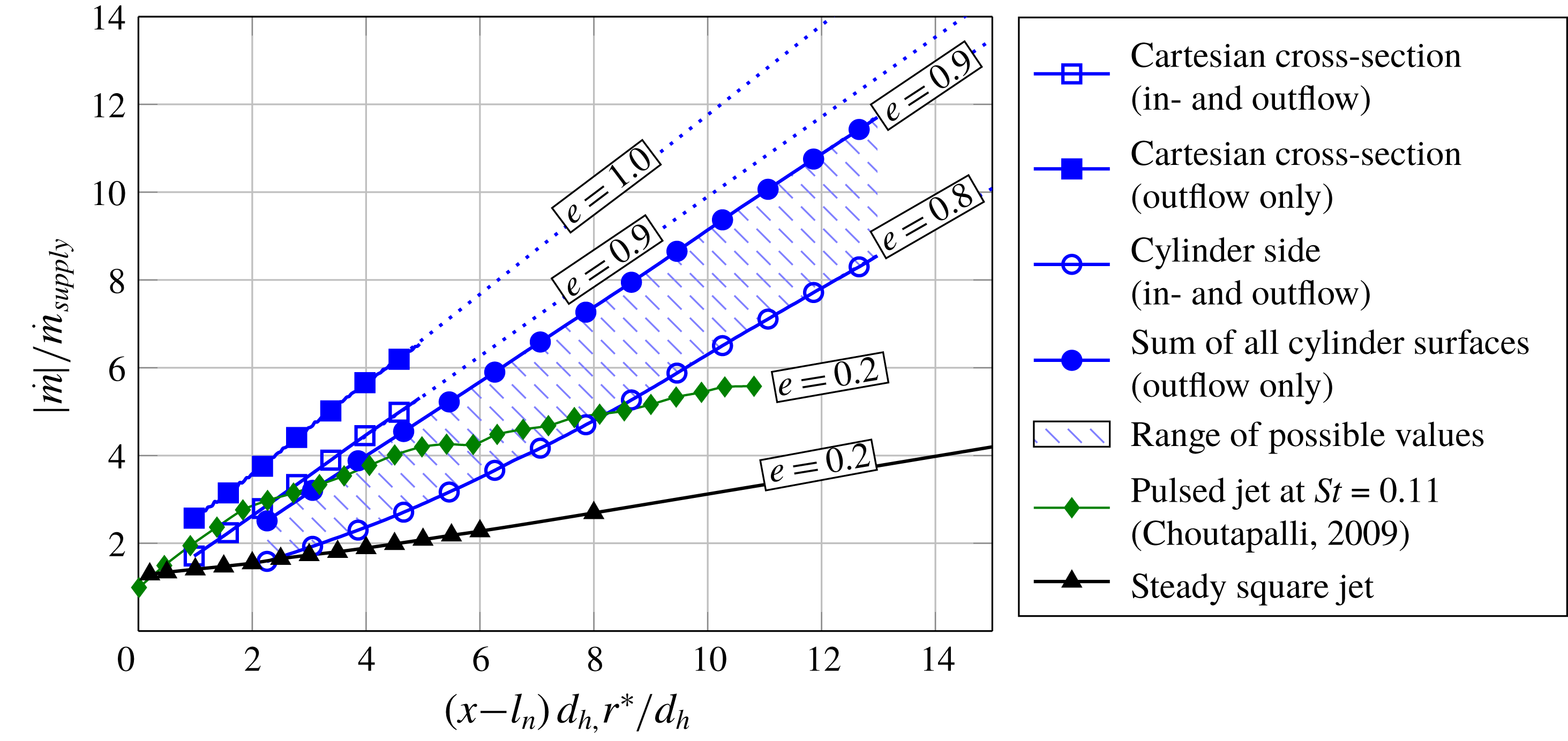
Figure 10 delineates the mass flow through all surfaces individually. It is challenging to extract the correct entrainment of the jet from these data. The sum of outflow through all surfaces certainly overestimates the entrainment because it includes effects such as recirculation from vortices and turbulence that do not contribute to the overall entrainment. In contrast, the combined flow through the cylinder side underestimates the total entrainment because local entrainment from areas close to the wall surface is subtracted throughout the integration (4.7). Therefore, the available data and applied methods only allow the conclusion that the actual entrainment is in between these two limits. The resulting range is illustrated in figure 11. The annotated entrainment
 $e$
is based on the linear trend of the data points farthest away from the nozzle. Note that the present data only capture the near field entrainment. It is conceivable that the entrainment rates
 $e$
may change at greater distances from the nozzle. In order to allow a comparison to other studies, the mass flows for Cartesian cross-sections (4.6) are added as well. Note that the data of the Cartesian cross-sections are limited to
 $(x-l_{h})/d_{h}<5$
because parts of the jet do not go through the domain-limited cross-section farther downstream. As expected, the entrainment obtained by integration over Cartesian cross-sections exceeds the results obtained in cylindrical coordinates due to the jet’s underestimated travel distance from the nozzle when the jet is deflected. Although omitted here, it may be possible to correct these data by introducing an effective distance from the nozzle based on an average deflection angle.
The comparison between the entrainment of the spatially oscillating jet and the steady jet in figure 11 reveals that the entrainment rate
 $e$
of the spatially oscillating jet is increased by at least a factor of four compared to the entrainment rate of a steady jet in the near field. This enhancement is expected to be a result of the spatial oscillation that increases the contact area between jet and surrounding fluid in
 $z$
-direction. It is noteworthy that generally the entrainment rate of square jets is slightly higher (i.e.
 $e\approx 0.3$
) than that measured in this study (Grinstein, Gutmark & Parr Reference Grinstein, Gutmark and Parr1995). This discrepancy is a result of the unconventional nozzle geometry (figure 1
b). However, the influence of the nozzle geometry and upstream effects are negligible compared to the entrainment enhancement by unsteady jets (Bremhorst Reference Bremhorst1979). The entrainment rate of the spatially oscillating jet is also higher than that of a pulsed jet at a Strouhal number of 0.11 that was assessed by Choutapalli et al. (Reference Choutapalli, Krothapalli and Arakeri2009). Choutapalli et al. (Reference Choutapalli, Krothapalli and Arakeri2009) suspect that the creation of the head vortex causes the high initial entrainment rate of pulsed jets. This entrainment rate is of the same order as the entrainment rate of the spatially oscillating jet. However, with increasing distance to the nozzle, the entrainment rate of the pulsed jet decreases to the entrainment rate of a steady jet. In contrast, the entrainment rate of the spatially oscillating jet remains constant throughout the range of examined distances. This suggests that the high entrainment rate of the spatially oscillating jet is caused by the increased entrainment from the direction normal to the oscillation plane instead of its head vortices. It is noteworthy that the entrainment rate of a spatially oscillating jet may decrease in the far field. However, the initially high entrainment rate most likely causes the spatially oscillating jet also to carry more mass flow than the comparable jets in the far field.
The combined mass flow through the cylinder side as a function of the supply rate.

Figure 12 depicts the entrainment of the spatially oscillating jet at discrete positions for various supply rates. It is evident that the entrainment is not affected by the supply rate. Therefore, the jet Reynolds number has no obvious effect on the entrainment rate within the investigated Reynolds numbers. Recalling that the oscillation frequency increases with the supply rate, it is evident that the oscillation frequency also does not change the entrainment rate within the range of captured oscillation frequencies. This is expected because the Strouhal number does not change with the supply rate. Hence, it supports the statement at the beginning of § 4 that the linear coupling between oscillation frequency and jet velocity does not allow for changing the Strouhal number or the dynamic behaviour of the flow field for the employed fluidic oscillator. Other oscillator designs may therefore experience other results. Note that differing results may also be expected in the sonic regime because the oscillation frequency stagnates once the jet velocity approaches sonic speed (Von Gosen et al. Reference Von Gosen, Ostermann, Woszidlo, Nayeri and Paschereit2015).
4.4 Jet forces
The oscillating jet acts with a certain force on the surrounding fluid. The magnitude of the jet force acting on the fluid is of interest for several applications such as flow control (i.e. determining the momentum coefficient). It is challenging to measure the jet force due to the spatial motion of the jet. Most studies that are employing the momentum coefficient use a force
 $F_{bulk}$
that is based on the assumption of ambient conditions at the jet exit and the jet bulk velocity
 $U_{bulk}$
in the exit throat
 $A_{outlet}$
(4.11):
 $$\begin{eqnarray}\displaystyle F_{bulk}=\unicode[STIX]{x1D70C}_{0}A_{outlet}U_{bulk}^{2}. & & \displaystyle\end{eqnarray}$$
However, figure 9(a) shows that the maximum velocity magnitude exceeds the bulk outlet velocity. Therefore, the actual force is likely underestimated. Thrust measurements with a one-component balance also underestimate the actual force because this neglects the lateral component. This may be resolved by employing a multi-component balance. However, a sufficiently low response time is required for resolving the time-dependent lateral force component at high oscillation frequencies. Here, the jet force
 $F$
is determined from the instantaneous velocity fields § 3 and phase averaged thereafter. The infinitesimal force
 $\text{d}F$
acting on the fluid in normal direction to the control surface is dependent on the local velocity
 $\boldsymbol{u}$
(4.12):
 $$\begin{eqnarray}\displaystyle \text{d}\boldsymbol{F}=\unicode[STIX]{x1D70C}\boldsymbol{u}(\boldsymbol{u}\boldsymbol{\cdot }\boldsymbol{n})\,\text{d}A. & & \displaystyle\end{eqnarray}$$
Spatially integrating the infinitesimal forces cancels out opposing forces. However, they also need to be considered for the jet force magnitude. Therefore, the infinitesimal force magnitude
 $|\text{d}F|$
is considered, which is a function of the local velocity magnitude acting in surface normal direction (4.13)–(4.14):
 $$\begin{eqnarray}\displaystyle & |\text{d}F|=|\unicode[STIX]{x1D70C}\boldsymbol{u}(\boldsymbol{u}\boldsymbol{\cdot }\boldsymbol{n})|, & \displaystyle\end{eqnarray}$$
 $$\begin{eqnarray}\displaystyle & =\unicode[STIX]{x1D70C}U(\boldsymbol{u}\boldsymbol{\cdot }\boldsymbol{n}). & \displaystyle\end{eqnarray}$$
The force magnitudes acting on the fluid are integrated along the cylinder surfaces to yield a total force magnitude
 $F$
(4.15)–(4.17):
 $$\begin{eqnarray}\displaystyle & \displaystyle F_{side}(r,\unicode[STIX]{x1D719})=\unicode[STIX]{x1D70C}_{0}\int _{-z_{max}}^{z_{max}}\int _{-\text{arccos}(l_{n}/2)}^{\arccos (l_{n}/2)}Uu_{r}r\,\text{d}\unicode[STIX]{x1D713}\,\text{d}z, & \displaystyle\end{eqnarray}$$
 $$\begin{eqnarray}\displaystyle & \displaystyle F_{base,1,2}(r,\unicode[STIX]{x1D719})=\pm \unicode[STIX]{x1D70C}_{0}\int _{l_{n}}^{r}\int _{-\text{arccos}(l_{n}/2)}^{\arccos (l_{n}/2)}Uu_{z}(z=\pm z_{max})r\,\text{d}\unicode[STIX]{x1D713}\,\text{d}r, & \displaystyle\end{eqnarray}$$
 $$\begin{eqnarray}\displaystyle & \displaystyle F_{wall}(r,\unicode[STIX]{x1D719})=-\unicode[STIX]{x1D70C}_{0}\int _{-z_{max}}^{z_{max}}\int _{-r}^{r}Uu_{x}\left(\unicode[STIX]{x1D713}=\arccos \frac{l_{n}}{r}\right)\,\text{d}r\,\text{d}z. & \displaystyle\end{eqnarray}$$
Analogous to the mass flow determination, it is possible to distinguish between force resulting from in- and outflow by integrating only positive or negative values of
 $(\boldsymbol{u}\boldsymbol{\cdot }\boldsymbol{n})$
. Note that the forces of in- and outflow are overestimated due to vortices and local turbulence that would cancel out in the combined flow. Figure 13 shows the jet force acting on the fluid along the cylinder surfaces. The forces are normalized by the bulk force (4.11). The outflow through the cylinder side results in the dominant force, which supports the selection of a cylindrical control volume. It is constant for all distances to the nozzle. The force resulting from the inflow through the wall surface (i.e. the supply mass flow) is the corresponding opposite force. The inflow through the cylinder base (i.e. the entrainment) results in an additional force acting on the fluid. The sum of time-averaged forces from all surfaces is approximately zero, which is consistent with the expected conservation of momentum and adds further confidence in the data quality. The slight decrease in total force from all surfaces may be attributed to a streamwise pressure gradient that is not assessed in this study.
Force magnitude acting on the fluid integrated along the cylinder surfaces.

Similar to the entrainment, it is not possible to determine the exact force emitted by the spatially oscillating jet. The forces obtained separately by in- and outflow through the cylinder side are overestimated due to turbulence and local vortices. When considering the combined flow, the force created by the inflow due to entrainment from that direction is subtracted from the total force, which yields an underestimated result. Hence, the range of possible values is bound by the force resulting from the total outflow through all surfaces and by the force resulting from the combined flow through the cylinder side. The resulting jet force is between 1.20 and 1.32 times the idealized force
 $F_{bulk}$
. Thus, a momentum coefficient determined from
 $F_{bulk}$
for a spatially oscillating jet is underestimated. Similar to the entrainment, the normalized jet force is independent of the supply rate.
The force acting on the fluid over the control surface oscillates throughout one oscillation period. The shaded area in figure 13 illustrates the range of oscillating values. It is evident that at
 $r^{\ast }/d_{h}=5$
, the force acting on the cylinder side surface oscillates most. This is caused by changing convection speeds that are a result of the oscillating jet velocity figure 8. As the jet moves from side to side, its exit velocity decreases and then increases again later within the oscillation period. The flow emitted at the later instance overtakes the previously emitted flow due to the higher jet velocity. This behaviour results in a temporary increase in force over the control surface followed by the opposite effect of a temporary force deficiency.
5 Conclusion
A spatially oscillating jet with an outlet throat aspect ratio of one is emitted from a fluidic oscillator into a quiescent environment. The three-dimensional flow field is measured plane-by-plane employing a stereoscopic PIV system. Simultaneously acquired time-resolved pressure signals from inside the nozzle enable to phase-average velocities and jet properties to be evaluated. The phase-averaged flow field visualizes the jet’s spatial oscillation and emphasizes the spread of fluid over a large area. Dominant flow features include alternating circular head vortices that are created repetitively when the jet is fully deflected. They are similar to the starting vortex known from time-dependent straight jets. Hence, the jet injects increased vorticity into the surrounding flow field. This may be advantageous for flow control applications that rely on mixing enhancement.
Quantitative jet properties are determined using a cylindrical coordinate system. The cylindrical coordinate system allows for an assessment of jet properties at constant distances from the nozzle throat throughout one oscillation cycle. The jet’s properties are temporally oscillating, which is caused by the internal geometry of the employed fluidic oscillators. It is anticipated that the general trends are not affected by the temporal oscillation because the amplitudes caused by the spatial oscillating are significantly higher. Nevertheless, future studies may prevent the temporal oscillation entirely for example, by using a mechanically turning steady jet nozzle with constant output. Furthermore, this approach would allow us to examine the influence of jet angle variation on the fundamental observations made in this study. For the investigated spatially oscillating jet, the jet’s maximum velocity decay rate is considerably higher than that of a comparable steady jet accompanied by a significant increase in jet depth. Both observations are indicative of a higher momentum transfer to the quiescent environment and thus for a higher entrainment. Conceptual constraints only allow us to provide a range of possible entrainment values for the spatially oscillating jet. Even within this range, the entrainment rate of the spatially oscillating jet exceeds the entrainment rate of a steady jet by at least a factor of four. Most of the additional mass flow is entrained from the direction normal to the oscillation plane because of the enlarged contact area between accelerated fluid and quiescent environment. The benefit of this three-dimensional effect is expected to be limited to small outlet aspect ratios. For higher outlet aspect ratios, the contribution of entrainment from the normal direction would decrease resulting in a decreased overall entrainment. This effect is one reason for previous controversies regarding the entrainment of spatially oscillating jets. In contrast, the oscillation frequency does not have any obvious effects on the entrainment within the investigated range of supply rates. This result supports the assumption that the Strouhal number accounts for changes in the dynamic behaviour of the flow field. Due to the coupling between oscillation frequency and supply rate for the employed fluidic oscillator, the Strouhal number is constant for all supply rates and oscillation frequencies in this study. It is left for future studies to analyse the effect of the Strouhal number.
The jet force of the spatially oscillating jet is shown to exceed the force of an idealized steady jet with the same mass flow by up to 30 %. This result may be of particular interest for the momentum coefficient that is generally used for comparing different flow control actuators. For flow control studies, the momentum coefficient is often based on the idealized steady jet approximation. Measuring the correct jet force is challenging because the lateral component of the instantaneous jet force cancels out during one oscillation period. However, it may be possible to correct for the underestimation by considering the jet deflection angle and oscillation pattern. It should be noted that for many flow control applications, these spatially oscillating jets are commonly operated in the compressible flow regime, which will make the correct assessment of total jet force even more challenging. Here, numerical approaches may provide a useful tool to confirm the presented results and extend the scope of this work.
Supplementary movie
A supplementary movie is available at https://doi.org/10.1017/jfm.2018.739.



