
I. INTRODUCTION
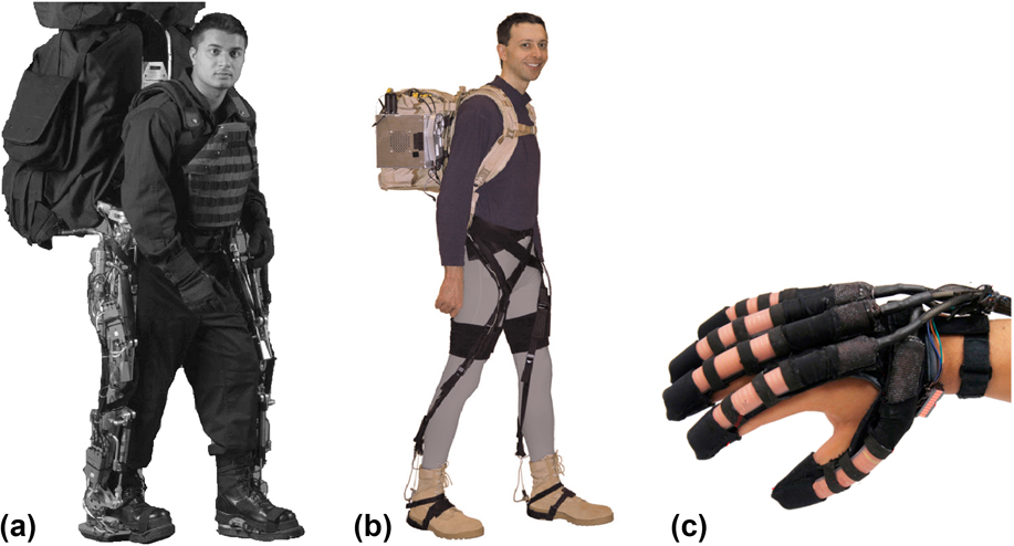
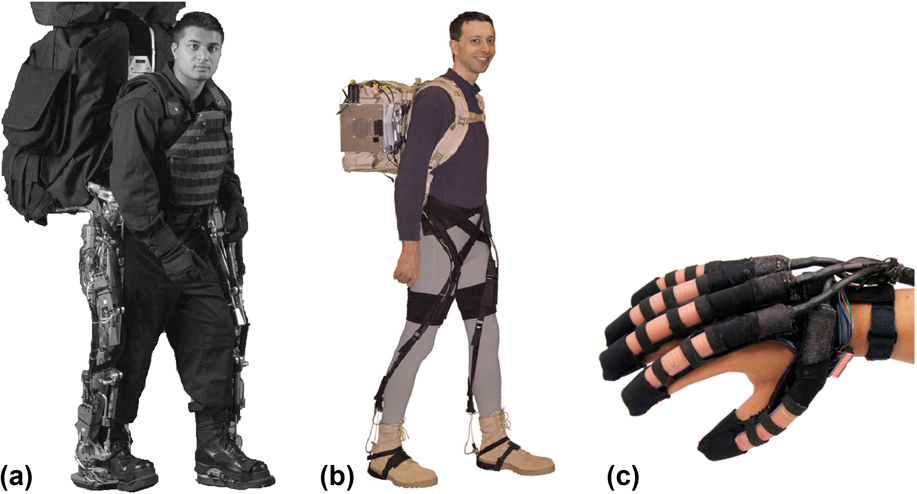
The development of wearable robotic suits for augmenting human movement or biomimetic soft robots that mimic the complex movements of biological organisms has gained considerable momentum recently through a paradigm shift in the materials used from hard and rigid to soft and compliant. Reference Shen1–Reference Rus and Tolley3 This shift reflects that user acceptance is an essential requirement for wearable technology Reference Viteckova, Kutilek and Jirina4–Reference Pons7 and any system that is in close and constant contact with the wearer's body must be comfortable. As Fig. 1 illustrates, the evolution of exoskeletons has reflected these requirements with the latest systems utilizing textile attachments, cable-drives, or soft pneumatic systems to deliver torques to limb joints. Reference Asbeck, de Rossi, Holt and Walsh8,Reference Polygerinos, Wanga, Galloway, Wood and Walsh9 While these lightweight exoskeletons have shown promise, benefits demonstrated to date have been small. Reference Mooney, Rouse and Herr10–Reference Malcolm, Derave, Galle and De Clercq12 Further reductions in size and weight of batteries and motor units are needed but achieving these goals with current technology comes at the cost of reduced mechanical assistance or shorter operating lifetimes. The next evolution in soft exosuits and soft robots seeks to replace the current motor systems with artificial muscle materials Reference Mattar13 that can provide considerably higher power–weight ratios compared with similar sized electric motors Reference Haines, Lima, Li, Spinks, Foroughi, Madden, Kim, Fang, de Andrade, Goktepe, Goketpe, Mirvakili, Naficy, Lepro, Oh, Kozlov, Kim, Xu, Swedlove, Wallace and Baughman14 thereby reducing motor mass.
Evolution of lower body and hand exoskeletons. (a) The first lower body exoskeleton capable of carrying a payload Reference Zoss, Kazerooni and Chu16 [© 2006 IEEE. Reprinted, with permission, from A. B. Zoss, H. Kazerooni and A. Chu, IEEE-ASME T. Mech. 11, 128 (2006)]; (b) cable-driven soft exosuit (© 2015 A. T. Asbeck, S. M. M. de Rossi, K. G. Holt, and C. J. Walsh, Int. J. Robot. Res. Vol. 34, p. 744. Reprinted by Permission of SAGE Publications, Ltd.); and (c) soft robotic pneumatic glove [Reprinted from Robot. Auton. Syst. Vol. 73, P. Polygerinos, Z. Wanga, K. C. Galloway, R. J. Wood and C. J. Walsh, p. 135. Copyright (2015), with permission from Elsevier].
The recently described spring-like polymer coil artificial muscles Reference Haines, Lima, Li, Spinks, Foroughi, Madden, Kim, Fang, de Andrade, Goktepe, Goketpe, Mirvakili, Naficy, Lepro, Oh, Kozlov, Kim, Xu, Swedlove, Wallace and Baughman14 are highly stretchable and compliant and are of particular interest for use in robotic garments and soft robotic devices. Reference Yip and Niemeyer15 As introduced by Baughman and co-workers, coiled polymer fiber artificial muscles are made by a simple twist insertion process using low-cost polymer textile fibers. The first reports of these thermally activated muscles demonstrated large contraction strains and work densities of over 2000 J/kg, which is 50 times higher than that generated by natural skeletal muscle. These new types of artificial muscles are still largely unexplored and further improvements in performance may be possible as more studies are conducted into different fibers and different coil geometries. The aim of this article is to review the current understanding of how the basic material structure and properties affect the performance characteristics of polymer coil artificial muscles.
II. MATERIAL PROPERTIES THAT DETERMINE ARTIFICIAL MUSCLE PERFORMANCE
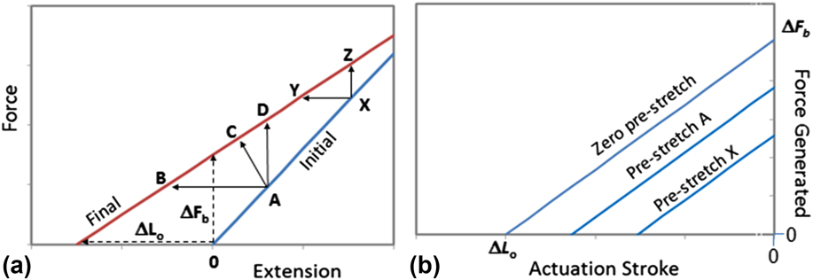
Artificial muscles generate displacements and forces that are usefully applied to external structures. It is important to recognize that the force and displacement (or stroke) generated for a given input stimulus will vary depending on the external loading conditions, Reference Giurgiutiu, Rogers, Rogers and Chaudhry17,Reference Spinks, Liu, Wallace and Zhou18 and the effects of external loads are particularly important when compliant actuators are used. The ‘force-stroke’ diagram (Fig. 2) is a common way to represent the mix of forces and displacements generated from a given actuator when given a certain stimulus. The maximum displacement occurs when the force is unchanged, and this condition is referred to as ‘isotonic’. In contrast, the maximum force is generated when the actuator displacement is blocked so that the actuator length remains unchanged, or ‘isometric’.
Illustration of theoretical actuation stroke and force relationships for a linear elastic actuator material: (a) force-extension curves in the initial (unactivated) and final (activated) states for the case of a contractile actuator with decreasing stiffness on activation. The displacements and/or forces generated during activation are illustrated by the arrows. Dashed arrows show the actuation free stroke (ΔL o) and blocked force (ΔF b) produced when there is no prestretch applied to the actuator; (b) actuation force–stroke curves showing the mixture of possible forces and displacements generated when the actuator is stimulated and for the three different prestretch levels shown in (a).
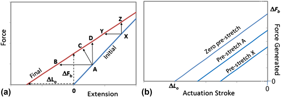
The force–stroke curves are derived from the basic force-extension curves generated by stretching or relaxing the actuator in the unactivated and activated states. As illustrated in Fig. 2(a), the force-extension relationship in uniaxial tension for a hypothetical linear elastic actuator can be represented by two lines corresponding to the initial (unactivated) and final (activated) states. The slope of each line represents the actuator stiffness, which is typically altered by the actuation stimulus, such as heat, light, electric field, or change in chemical environment. The force-extension line in the activated state is offset along the horizontal axis to reflect the change in actuator length caused solely by the stimulus and in the absence of an externally applied force. Prestretching the actuator to point A followed by stimulation can generate a mix of actuation generated forces (ΔF A) and strokes (ΔL A) as illustrated by the arrows from A to B, C, and D. The two extreme cases of isotonic and isometric are shown by arrows A–B and A–D, respectively. The importance of prestretch is seen by comparing the expected actuation behavior when the artificial muscle is prestretched to point A or to point X. In the example given in Fig. 2, the higher prestrain (point X) generates smaller isotonic strains (X–Y) and smaller isometric stresses (X–Z) than when a smaller prestrain was imposed (A–B and A–D, respectively). The force–stroke curves of Fig. 2(b) also demonstrate the effect of prestretch on the force and strokes generated by a given input stimulus.
For linear elastic materials, the force–stroke curve is a straight line with a slope equivalent to the actuator material's stiffness in the activated state and described by the following expression where ΔF A and ΔL A are the actuation force and stroke generated after the actuator is prestretched to an initial force of F A:
 $$\Delta {F_{\rm{A}}} = {k'_{\rm{A}}}\left( {\Delta {L_{\rm{A}}} - \Delta {L_{\rm{o}}}} \right) + {F_{\rm{A}}}\left( {{{{{k'}_{\rm{A}}}} \over {{k_{\rm{A}}}}} - 1} \right)\quad .$$
k
A and
 ${k'_{\rm{A}}}$
are the actuator material's stiffnesses in the unactivated and activated states, respectively. Equation (1) can be rearranged to show how actuation stroke is the numerical sum of the free stroke (ΔL
o) and the difference in the deformation induced as the external load changes from the initial load (FA
) to the final load
 $\left( {{{F'}_{\rm{A}}}} \right)$
:
 $$\Delta {L_{\rm{A}}} = \Delta {L_{\rm{o}}} + {{{{F'}_{\rm{A}}}} \over {{{k'}_{\rm{A}}}}} - {{{F_{\rm{A}}}} \over {{k_{\rm{A}}}}}\quad .$$
Equations (1) and (2) can be used to derive the actuation performance under any external loading conditions, including isometric, isotonic, or when both actuator length and force vary. The latter includes exoskeleton muscles that rotate limbs and when the actuator operates against a deformable object. The only material parameters that are needed to define these actuation performances are the free stroke (at zero applied load) and the actuator stiffnesses before and after activation. The material structures that affect these parameters are considered in the following sections for polymer coil muscles.
III. ACTUATION PERFORMANCE OF POLYMER COIL MUSCLES
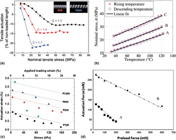
Actuation studies reported to date for polymer coil muscles have only considered the isotonic (ΔF A = 0) Reference Haines, Lima, Li, Spinks, Foroughi, Madden, Kim, Fang, de Andrade, Goktepe, Goketpe, Mirvakili, Naficy, Lepro, Oh, Kozlov, Kim, Xu, Swedlove, Wallace and Baughman14 or isometric (ΔL A = 0) Reference Cherubini, Moretti, Vertechy and Fontana19 actuation behaviors. These studies have investigated the effect of prestretch on the isotonic actuation strain [Fig. 3(a)] and isometric actuation force generated [Fig. 3(b)]. Isotonic measurements have shown that the magnitude of the contraction strain on heating first increased when the preload was increased and then remained mostly unchanged at higher applied loads. At small preloads the coiled fibers were insufficiently stretched to allow room for the full contraction without inhibition due to physical contact between adjacent fiber turns in the coiled structure, as shown by the inset photographs in Fig. 3(a). Above a certain preload level, the contraction strains remain constant since the full contraction can be achieved without coil–coil contact. Isometric actuation tests Reference Cherubini, Moretti, Vertechy and Fontana19 have shown that the force generated increases linearly with temperature and the force—temperature coefficient increases only slightly with increasing preloading.
Isotonic actuation strains (a and c) and isometric force/stress generated (b and d) for different prestress levels: (a) polymer coil muscles made from nylon-6,6 monofilament prepared by over-twisting at different loads to control the spring index (C = coil diameter/fiber diameter). Inset photographs show the prestretched initial (cool) state and the final hot state when physical contact occurs between adjacent turns in the coil [From C. S. Haines et al., Science 343, 868 (2014). Reprinted with permission from AAAS.]; (b) polymer coil muscles from nylon-6,6 fibers and prestretched to 14% (A), 21% (B), and 29% (C) (Reprinted from A. Cherubini, G. Moretti, R. Vertechy, and M. Fontana, AIP Adv. 5, 067158 (2015) with the permission of AIP Publishing.); (c) polypyrrole laminated on corrugated rubber sheet with corrugation amplitude decreasing in the order P120 > P240 > P600 > P1200. Actuation strains are contractions. [Reprinted from W. Zheng, G. Alici, P. R. Clingan, B. J. Munro, G. M. Spinks, J. R. Steele, and G. G. Wallace, J. Polym. Sci. Pt. B: Polym. Phys. 51, 57 (2013) with the permission of Wiley.] (d) polypyrrole fibers with integrated platinum wire as a single fiber (A) of 4 fiber bundle (B). [© IOP Publishing. Reproduced with permission from G. M. Spinks, T. E. Campbell, and G. G. Wallace, Smart Mater. Struct. 14, 406 (2005). All rights reserved.]

The near independence of actuator strain and stress generated by polymer coil muscles on preload is unusual, as most artificial muscles show a decreasing actuation response with an increase in preloading. Figures 3(c) and 3(d) give illustrative examples from conducting polymer artificial muscles for the purpose of comparison. Figure 3(c) shows the isotonic strains generated by stretchable conducting polymer/rubber laminates Reference Zheng, Alici, Clingan, Munro, Spinks, Steele and Wallace20 where the rubber film surface was corrugated to allow the polypyrrole coating to be stretched without cracking. These composite actuators were electromechanically active even when stretched to 20% prestrain, although the actuation stroke decreased as the preload force increased. Similarly, polypyrrole fibers exhibited a strong decay in the isometric force generated as the preload force increased [Figs. 3(d)]. Reference Spinks, Campbell and Wallace21
The effect of preloading on isotonic actuation strain and isometric actuation stress has previously been shown to be related to changes in actuator stiffness on activation
 $\left( {{{k'}_{\rm{A}}} \lt \;{k_{\rm{A}}}} \right)$
,
Reference Spinks, Liu, Wallace and Zhou18,Reference Spinks, Campbell and Wallace21
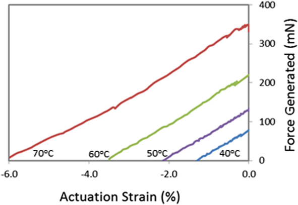
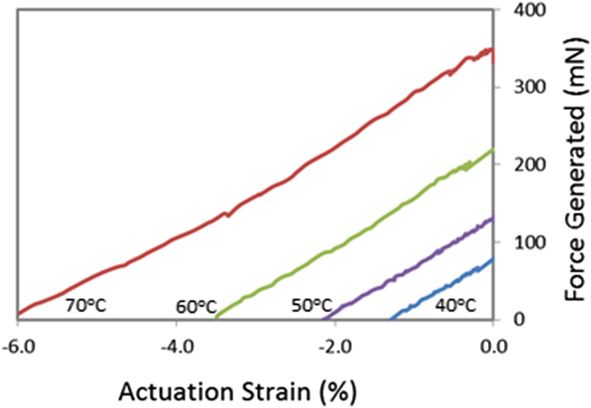
as shown in Eqs. (1) and (2). The stiffnesses of the conducting polymer actuators described in Figs. 3(c) and 3(d) have been shown to be smaller in the contracted state compared with the expanded state. Consequently, the magnitude of the contraction strain and the tensile force generated will both decrease as the preload force increases [Figs. 3(c) and 3(d)]. The near independence of the isotonic actuation strains [above the critical preload level, Fig. 3(a)] and isometric actuation stresses generated by polymer coil muscles [Fig. 3(b)] on the applied load suggests that the coil stiffness changes little during heat activation. This conclusion is supported by the force stroke curves for polymer coils made by over-twisting commercially available silver-coated nylon-6 yarns that are shown in Fig. 4. The coils were heated to temperatures in the range of 40–70 °C and the force–stroke curves were measured. The slopes of these curves are almost identical showing that the stiffness was unchanged by heating over this range of temperatures.
Force–stroke curves obtained from polymer coil muscles fabricated from silver-coated nylon yarn electrothermally heated to temperatures in the range 40 °C–70 °C, as indicated.
IV. SPRING STIFFNESS OF POLYMER COIL MUSCLES
The stiffness of helical springs is defined by the spring wire diameter (d), coil diameter (D), number of turns in the coil (N), and the material's shear modulus (G):
 $$k = {{G{d^4}} \over {8{D^3}N}}\quad .$$
The change in stiffness of polymer coil muscles will be determined by the competing effects of the reduction in modulus and the increase in fiber diameter that both occur simultaneously during heating. For example, heating monofilament nylon-6 fibers of different diameters from 26 °C–62 °C caused the fiber diameter to increase by ∼2.5% Reference Aziz, Naficy, Foroughi, Brown and Spinks22 and a simultaneous reduction in modulus of ∼10%. Reference Aziz, Naficy, Foroughi, Brown and Spinks23 As shown by Eq. (3), these two effects exactly cancel when coil geometries do not change so that the coil stiffness remains constant.
V. TENSILE–TORSIONAL ACTUATION COUPLING IN POLYMER COIL MUSCLES
Tensile actuation in polymer coil muscles is derived directly from a torsional actuation that occurs in the twisted fiber that forms the coil. Reference Haines, Lima, Li, Spinks, Foroughi, Madden, Kim, Fang, de Andrade, Goktepe, Goketpe, Mirvakili, Naficy, Lepro, Oh, Kozlov, Kim, Xu, Swedlove, Wallace and Baughman14 The same mechanics that governs the tensile extension or compression of helical springs has been shown to apply to the tensile actuation of polymer coil muscles. Spring mechanics relate the change in the length of the coiled spring (ΔL) to the amount of twist (ΔT) that occurs in the spring wire during coil extension:
 $$\Delta L = {{{l^2}\Delta T} \over N}\quad ,$$
where l is the length of the wire or fiber that makes up a helical spring on N turns. The same expression has been found to accurately describe the tensile stroke in polymer coil muscles. Reference Haines, Lima, Li, Spinks, Foroughi, Madden, Kim, Fang, de Andrade, Goktepe, Goketpe, Mirvakili, Naficy, Lepro, Oh, Kozlov, Kim, Xu, Swedlove, Wallace and Baughman14 Twisted polymer fibers are known to reversibly and partially untwist when volume increases. Reference Foroughi, Spinks, Wallace, Oh, Kozlov, Fang, Mirfakhrai, Madden, Shin, Kim and Baughman24 This torsional actuation then causes a change in length of coils that are made from the twisted fiber. Figure 5 shows experimentally measured coil strains Reference Haines, Lima, Li, Spinks, Foroughi, Madden, Kim, Fang, de Andrade, Goktepe, Goketpe, Mirvakili, Naficy, Lepro, Oh, Kozlov, Kim, Xu, Swedlove, Wallace and Baughman14 for four samples made by first twisting a nylon-6 monofilament and then forming the twisted fiber into coils of different coil bias angles by wrapping around a mandrel. The bias angle is reported with respect to the long axis of the fiber. In one case, the coil wrap direction was opposite to the fiber twist direction and heating caused coil length expansion. In all other cases, the coil wrap and fiber twist were in the same direction so that heating produced a coil length contraction. The dashed lines in Fig. 5 are the calculated results from Eq. (4) that shows excellent agreement with the experimentally measured values. The only discrepancy occurred in the coil of an initial coil bias angle of 85° at higher temperatures where physical contact between adjacent turns in the coil restricted the experimentally achievable contraction.
Measured polymer coil muscle actuation strains (symbols) when heated from room temperature to 50 °C. Dashed lines are values calculated from Eq. (4). Coils were made from twisted nylon-6 monofilament that was mandrel-wrapped to form coils with the indicated coil bias angles.

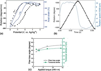
The coupling between tensile actuation in polymer coil muscles and the torsional actuation occurring in the coil fiber is satisfying since the discovery of tensile actuation in polymer coils was a direct result of earlier studies into the torsional actuation of twisted fibers and yarns. Reference Foroughi, Spinks, Wallace, Oh, Kozlov, Fang, Mirfakhrai, Madden, Shin, Kim and Baughman24,Reference Lima, Li, de Andrade, Fang, Oh, Spinks, Kozlov, Haines, Suh, Foroughi, Kim, Chen, Ware, Shin, Machado, Fonseca, Madden, Voit, Galvão and Baughman25 Volume increases in highly twisted carbon nanotube yarns, and later niobium nanowire yarns, Reference Mirvakili, Pazukha, Sikkema, Sinclair, Spinks, Baughman and Madden26 were shown to cause a partial untwisting and associated rotation of the fiber. For example, swelling caused by electrochemical charging of carbon nanotube yarns in a liquid electrolyte generated rotations of up to 180° per mm of yarn length [Fig. 6(a)] and rotation speeds of up to 600 revolutions per minute. Reference Foroughi, Spinks, Wallace, Oh, Kozlov, Fang, Mirfakhrai, Madden, Shin, Kim and Baughman24 Full recovery of the untwisting occurred when the volume expansion was reversed by discharging, but only when the yarn was connected to a nonactuating ‘return spring’ fiber. The effects of this and other testing configurations on the torsional actuation stroke and torque have been recently elaborated. Reference Aziz, Naficy, Foroughi, Brown and Spinks23 Forming composite yarns by impregnating the porous carbon nanotube or niobium nanowire twisted yarns with a guest material, such as paraffin wax, enabled the preparation of totally dry, electrolyte-free torsional muscles [Fig. 6(b)]. The basic mechanism of torsional actuation in these hybrid yarns remained the same as that of the original electrochemically driven torsional muscles, with yarn volume expansion driving the yarn untwist. Heating and cooling of the hybrid yarns generated the needed volume changes for reversible actuation. Heat could be from any source, but electrothermal Joule heating is the most convenient. Importantly, the same torsional actuation processes observed in twisted yarns also occur in twisted polymer fibers where thermal volume expansion causes fiber rotation [Fig. 6(c)].
Torsional actuation stroke (rotation) in (a) carbon nanotube yarns during electrochemical charging and discharging in a liquid electrolyte [from J. Foroughi et al., Science 334, 494 (2011). Reprinted with permission from AAAS.]; (b) hybrid carbon nanotube yarns containing paraffin wax and electrothermally heated (from M. D. Lima et al., Science 338, 928 (2012). Reprinted with permission from AAAS.); (c) twisted nylon-6 monofilaments prepared by twisting at different maximum applied torques and tested by heating from 20 °C to 160 °C in an oven. [From C. S. Haines et al., Science 343, 868 (2014). Reprinted with permission from AAAS.]

VI. MECHANISM OF TORSIONAL ACTUATION IN TWISTED FIBERS AND YARNS
Insight into the mechanism of torsional actuation in twisted fibers and yarns is obtained by treating the system as a single ‘string’ that is helically wrapped around a cylinder whose volume is changeable. Reference Haines, Lima, Li, Spinks, Foroughi, Madden, Kim, Fang, de Andrade, Goktepe, Goketpe, Mirvakili, Naficy, Lepro, Oh, Kozlov, Kim, Xu, Swedlove, Wallace and Baughman14,Reference Aziz, Naficy, Foroughi, Brown and Spinks22 The real structure of twisted fibers and yarns is more complex, but the single helix analogy has proven to be remarkably accurate in predicting the torsional rotation of twisted nylon-6 fibers. Reference Aziz, Naficy, Foroughi, Brown and Spinks22 The model is described more fully in recent publications Reference Haines, Lima, Li, Spinks, Foroughi, Madden, Kim, Fang, de Andrade, Goktepe, Goketpe, Mirvakili, Naficy, Lepro, Oh, Kozlov, Kim, Xu, Swedlove, Wallace and Baughman14,Reference Aziz, Naficy, Foroughi, Brown and Spinks22 and establishes the geometrical relationship between the length of the ‘string’ (L s), the volume, length, and diameter of the ‘cylinder’ (v, l, and d), and the number of turns that the string is wrapped around the cylinder (n), as in the following equation:
 $${v \over {{v_{\rm{o}}}}} = {\left( {{{{n_{\rm{o}}}} \over n}} \right)^2}\left( {{l \over {{l_{\rm{o}}}}}} \right)\left( {{{l_{\rm{s}}^2 - {l^2}} \over {l_{{\rm{s,o}}}^2 - l_{\rm{o}}^2}}} \right)\quad ,$$
where zero subscripts represent the initial values. Rearranging Eq. (5) gives an expression representing the torsional actuation in terms of the change in fiber twist that is induced by a change in cylinder volume:
 $$\Delta T = {{{n_{\rm{o}}}} \over {{l_{\rm{o}}}}}\left[ {{{\left( {{{{v_{\rm{o}}}} \over v}} \right)}^{1/2}}{{\left( {{l \over {{l_{\rm{o}}}}}} \right)}^{1/2}}{{\left( {{{l_{\rm{s}}^2 - {l^2}} \over {l_{{\rm{s,o}}}^2 - l_{\rm{o}}^2}}} \right)}^{1/2}} - 1} \right]\quad .$$
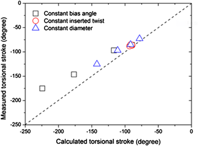
Experimentally measured torsional actuation stroke and volume expansion of nylon-6 fibers having different diameters and prepared with different inserted twist agreed closely with values calculated from Eq. (6) when the string length was assumed to be unchanged by heating. Reference Aziz, Naficy, Foroughi, Brown and Spinks22 Torsional actuation was generated by heating the samples from 25 °C to 62 °C where the twisted fiber length change was negligible, so that Eq. (6) simplifies to:
 $$\Delta T = {{{n_{\rm{o}}}} \over {{l_{\rm{o}}}}}\left( {{{{d_{\rm{o}}}} \over d} - 1} \right)\quad .$$
The close agreement between the experimental results and those calculated from Eq. (7) are shown in Fig. 7. The remarkable degree of agreement can be understood if the twisted fiber is thought of as a series of nested, concentric cylinders of increasing diameter, each with a helically wrapped string. All of these cylinders have the same amount of inserted twist (n o/l o) and if all displayed the same diameter expansion ratio, then according to Eq. (7) they would generate the same torsional actuation stroke. The real fiber structure, however, likely involves entangled helices of oriented polymer chains and these entanglements may affect the degree of “co-operation” between inner and outer cylinders in generating the torsional actuation. The data of Fig. 7 suggest that at smaller amounts of inserted twist the “co-operation” is good and all layers operate in synchronicity. However, at higher twist insertion some process slightly impedes the untwisting mechanism so that the measured torsional stroke is slightly less than predicted.
Comparison of measured and calculated torsional strokes for nylon-6 monofilaments of different diameter, different bias angles and different amounts of inserted twist. [Reprinted from S. Aziz, S. Naficy, J. Foroughi, H. R. Brown, and G. M. Spinks, J. Polym. Sci. Pt. B: Polym. Phys. 54, 1278 (2016) with the permission of Wiley.]
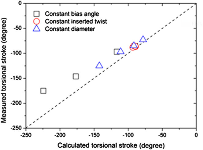
The only assumption used in applying Eq. (6) to the experimental data was the inextensibility of the string (l s,o = l s). For the twisted nylon fibers the “string” can be thought of as the oriented polymer chains that were originally aligned along the fiber axis but become helices by twist insertion. These molecules are likely highly extended and firmly connected through crystalline blocks. This topology exhibits a high axial stiffness and it is reasonable to be considered mechanically inextensible.
VII. FIBER TORSION–FIBER VOLUME RELATIONSHIPS
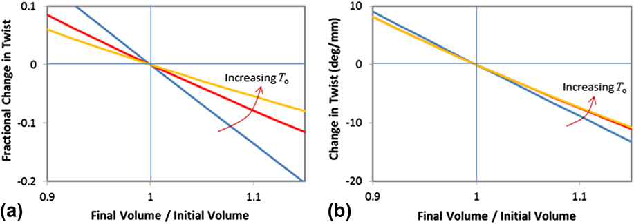
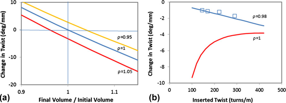
The single helix model provides a basis to explore how fiber volume expansion affects the torsional actuation stroke and, by correlation, the tensile actuation stroke in coiled muscles. The starting point is to assume isotropic volume expansion and consider the effect of inserted twist on the torsional actuation stroke [Fig. 8(a)] as represented by the fractional change in twist (ΔT) normalized to the initial twist T o = n o/l o. Regardless of the amount of inserted twist, an isotropic volume increase causes an untwist in the fiber where again the ‘string’ length is considered unchanged. Adding more twist to the fiber actually leads to a smaller fractional change in twist for a given fiber volume change. However, the torsional actuation stroke shows a smaller dependency on the initially inserted twist, as shown in Fig. 8(b), since the higher inserted twist partially offsets the reduced fractional change in twist during isotropic volume expansion.
Calculations of (a) fractional change in fiber twist and (b) absolute change in twist for three fibers having different initial twist densities. Calculations assume isotropic volume expansion and were based on fibers of 1 mm initial diameter, 100 mm initial length and initial inserted twists of T o = 180, 264, and 357 turns/m.
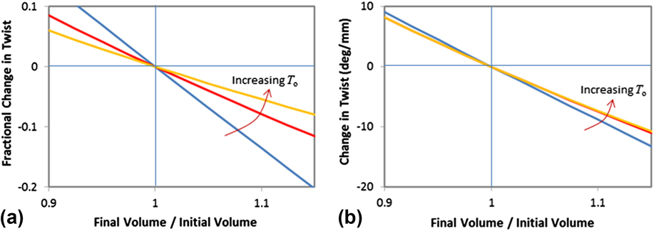
The results of Fig. 8 seem initially at odds with the experimental results presented in Fig. 7 where the torsional stroke was observed to be strongly dependent on the amount of inserted twist, as described by Aziz. Reference Aziz, Naficy, Foroughi, Brown and Spinks22 These and other experimental results for fiber torsion have all shown a strong anisotropy in volume change, with volume expansions typically dominated by relatively larger diameter direction expansions compared with the length direction. The theoretical effects of such volume change anisotropy can be explored by introducing an anisotropy parameter (ρ) to represent the ratio of the expansivity in the length direction (λ l ) to the expansivity in the fiber diameter direction (λ d ):
 $$\rho = {{{\lambda _l}} \over {{\lambda _d}}}\;{\rm{and}}\;{\lambda _d} = {d \over {{d_{\rm{o}}}}}\quad {\lambda _l} = {l \over {{l_o}}}\quad .$$
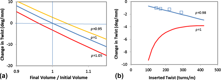
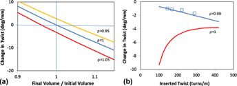
Figure 9(a) illustrates three different anisotropies with the torsional stroke calculated using Eq. (6) for different volume ratios and for a fixed initial inserted twist. The anisotropy parameter defines the length and diameter ratios for a given volume change. The torsional untwisting of the fibers due to a volume increase is significantly enhanced when the volume expansion is anisotropic with length expansion dominating in comparison to diameter expansion (ρ > 1). In addition, the torsional actuation is reduced in magnitude when the anisotropy of volume expansion is predominantly in the diameter direction (ρ < 1). Since this latter type of anisotropy is most commonly encountered in practice, there may exist an opportunity to increase torsional actuation by designing and developing twisted fibers and yarns that have the reverse anisotropy: small diameter changes and larger length changes. Figure 9(b) shows the results that match those of the experiments described in Fig. 7, where the measured anisotropy parameter was ρ = 0.98 and the measured volume expansion ratio was 1.04. Since the fiber length does not change, the theoretical torsional actuation is given by Eq. (7) and is proportional to the amount of inserted twist. These calculated results match closely the measured values. The theoretical results for the isotropic volume expansion are also shown for comparison. Here, considerably larger torsional strokes are expected, especially at low levels of inserted twist.
a) Calculated torsional actuation strokes for 100 mm long twisted fibers at different volume ratios and considering three different volume anisotropies given by the anisotropy parameter ρ: isotropic ρ = 1; anisotropic with predominant length change is ρ > 1; and anisotropic with predominant diameter change is ρ < 1. (b) Calculated and experimentally measured torsional actuation strokes for fibers prepared with different inserted twist and with a measured thermal expansion anisotropy of ρ = 0.98. The volume expansion ratio was 1.04. The calculated isotropic actuation strokes (ρ = 1) are given for comparison.
VIII. ORIGIN OF ANISOTROPIC VOLUME EXPANSION IN ORIENTED POLYMER FIBERS
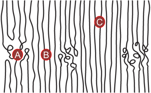
Experimental studies have shown that thermal expansion in oriented polymer fibers can be highly anisotropic. Reference Aziz, Naficy, Foroughi, Brown and Spinks23,Reference Choy, Chen and Young27 Typically, oriented polymers show small expansions and sometimes contractions in the length direction on heating along with diameter direction expansion of significantly larger magnitude. Reference Choy, Chen and Young27 Thermal contraction in the fiber length direction has been attributed to contributions from both crystalline and noncrystalline regions in the oriented fiber. Reference Choy, Chen and Young27 Crystal blocks and the crystalline bridges that form between these blocks are mostly aligned, with the polymer chain direction parallel to the fiber draw direction. The thermal expansion due to the crystalline regions is negative in the chain direction for polymers like polyethylene and nylon. Reference Kobayashi and Keller28 However, this contribution is small and the major contribution to the negative thermal expansion in the fiber direction comes from the rubber-like elasticity of the extended amorphous tie molecules in the intercrystalline regions. Reference Choy, Chen and Young27 These chains remain highly extended after drawing as a result of the formation of the crystalline bridges. The bridges form during drawing and increase in volume fraction, at the expense of the amorphous material, as draw increases. After drawing, the unloaded polymer will have a parallel arrangement of the crystalline bridges (region B in Fig. 10) and extended amorphous tie molecules (region A in Fig. 10) between the crystal blocks (region C in Fig. 10). The intercrystal separation distance and fiber length is determined by a force balance between the contraction of the extended tie molecules and the resistance due to the corresponding compression of the crystalline bridges. The intercrystalline distance is then sensitive to the moduli of the tie molecules and the crystalline bridges and the volume fraction of each phase. When heated, the modulus of the amorphous tie molecules increases due to the thermodynamics of rubber elasticity Reference Treloar29 and thereby further compresses the crystalline bridges since the modulus of the crystalline bridges does not change appreciably on heating. The net result is a thermal contraction in the draw direction (up to −40 × 10−5 K−1) that is much larger than the change in dimensions of the crystal lattice. Reference Choy, Chen and Young27 This mechanism operates only at temperatures above the T g of the polymer.
Schematic structure of a semicrystalline polymer fiber after drawing, showing: (A) amorphous tie-chains, (B) crystalline bridges, and (C) connecting crystalline blocks, aligned in the direction of draw. The figure is not drawn to scale and the relative proportions of regions A, B, and C depend on the type of polymer and processing conditions used to prepare the fiber, as discussed by Choy, Chen, and Young. Reference Choy, Chen and Young27
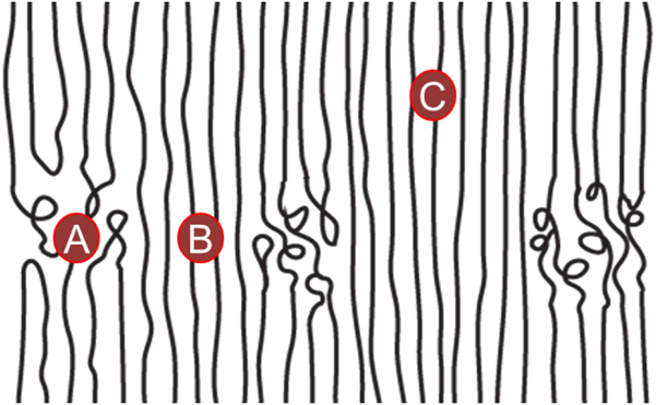
Perpendicular to the draw direction, the radial thermal expansion of amorphous tie molecules is restricted by the thermal expansion of crystalline regions and crystalline bridges (Fig. 10). Depending on the volume ratio of amorphous tie-chains to crystalline bridges as well as the draw ratio, the thermal expansion in this direction can approach that of a unit crystalline cell normal to the draw direction.
These same processes are likely to occur in the twisted polymer fibers. However, the helical orientation of the polymer chains and crystalline regions leads to complex geometrical coupling and much is still to be understood of the anisotropic thermal expansion in these materials.
IX. SCALING EFFECTS ON THE PERFORMANCE OF POLYMER COIL MUSCLES
The question of how the performance of polymer coil muscles scale with fiber dimensions and coil geometries can be approached by combining the single helix and spring mechanics models. The reorganized Eq. (4) is the product of three terms that assist in predicting scalability:
 $${{\Delta L} \over L} = \left( {{l \over L}} \right)\left( {{l \over {Nd}}} \right)\left( {d\Delta T} \right)\quad .$$
The first two terms relate to the coil geometry defined by the coil bias angles (αc), diameter (D), and number of turns (N). The first term in Eq. (9) is simply the inverse of cos αc (= L/l) and the second term is proportional to sin αc (= πND/l), since the coil diameter (D) is approximately double the fiber diameter (d) in coils made by over-twisting fibers. The final term is also scale invariant for twisted fibers where the degree of fiber untwist during actuation is proportional to the twist inserted during coil formation (T
o) (i.e., ΔT = cT
o where c is a constant), and
 ${T_{\rm{o}}} = \tan \,{\alpha _{\rm{f}}}/\pi d$
. As described above, experimental studies of twisted nylon-6 fibers have confirmed the correlation between torsional actuation stroke (ΔT) and the amount of inserted twist (T
o). It has been observed that over-twisted fibers made from different diameter fibers end up with the same fiber twist bias angle and coil bias angle. Consequently, the coil actuation strokes are expected to be the same for coils made from different diameter fibers.
The self-similarity of coil geometries made by over-twisting can be understood from the mechanics of coil formation. Insertion of twist is accommodated by fiber torsion and/or fiber bending when coils form and the appearance of coils, kinks, or snarls has been evaluated by consideration of minimum strain energies. The criterion by Ross Reference Ross30 is one such example and defines the critical torque (τc) needed to initiate coiling in fibers held under a tension force F:
 $${\tau _{\rm{c}}} = \sqrt {2EIF} \quad ,$$
where E is the material's Young's modulus and I is the second moment of area which is πd 4/64 for a fiber of circular cross-section and diameter d. When twisting is conducted at the same tensile stress (σ = 4F/πd 2 ), the critical twist insertion that initiates coiling according to the Ross criterion is:
 $${T_{\rm{c}}} = {{{\tau _{\rm{c}}}} \over {JG}} = {{32{E^{1/2}}{\sigma ^{1/2}}} \over {\sqrt 2 Gd}}\quad ,$$
where J is the polar moment of inertia which is πd 4/32 for fibers of circular cross-section and diameter d, and G is the shear modulus of the fiber material. Equation (11) shows that the critical twist at which coiling is initiated is inversely proportional to fiber diameter.
The final fiber twist at the completion of coiling can be determined through the concept of the Linking Number (L k). Reference Fuller31 This parameter is simply the number of rotations inserted into a fiber by rotating one fiber end and is the sum of fiber twist and writhe or:
 $${L_{\rm{k}}} = Tl + N\left( {1 - \cos \,{\alpha _c}} \right)\quad .$$
The formation of a coil requires the fiber to twist and the extent of twist depends on the coil bias angle. Equation (12) illustrates that after the initiation of coiling, the insertion of one additional rotation into the fiber (ΔL k = 1) will produce 1/(1 − cos αc) additional coils if the twist in the fiber remains unchanged. Experimentally, it is noted that the coiled fibers formed by over-twisting are packed tightly with a coil diameter approximately twice the fiber diameter. In such cases the coil bias angle will be αc = cos−1(1/2π) or 81° and the ratio of new coil turns formed per fiber end rotation is then 1.18. These parameters are very close to experimentally measured coil bias angles (∼78°) and measured coil turns formed per rotation (1.14). Consequently, the fiber twist remains mostly unchanged from the point of coil initiation until the formation of the fully coiled fiber. From this result, it can be concluded that the torsional actuation occurring in the fiber that forms the coil will be the same as in the fiber twisted to the onset of coiling.
Tensile strokes from over-twisted fibers may be independent of fiber diameter, but the force generated by the coiled muscles will increase with the fiber diameter. The blocked force can be estimated from the product of tensile stroke (ΔL) and the coil stiffness, as given by Eq. (3). Taking coil diameter to be approximately double the fiber diameter in coils formed by the over-twisting method, Eq. (3) shows that the coil stiffness increases linearly with fiber diameter. Blocked forces are also expected to scale linearly with fiber diameter. The mechanical work output of the actuator will depend on the external loading conditions, but the maximum work output (W
max) will be proportional to the product of tensile stroke and blocked force or
 ${W_{\max }}\, \propto\, k\Delta {L^2}$
. Combining Eqs. (3) and (4) and normalizing to the volume of the fiber gives the maximum volumetric work output for over-twisted coils:
 $${W_{\max }} = {{{\pi ^2}G\Delta {T^2}{d^2}} \over {8\,{{\sin }^3}\,{\alpha _{\rm{c}}}}}\quad .$$
Since it has been established above that the torsional stroke generated from over-twisting nylon-6 fibers to form coils is dependent of the inverse of fiber diameter, Eq. (13) shows that the maximum work output from such polymer coil muscles is independent of fiber diameter. Over-twisted fibers generate the same maximum work per volume (or mass) regardless of the fiber diameter.
Power density will be related to the speed at which the torsional actuation can occur and this can be assumed to match the tensile actuation rate if inertia effects are ignored. Heat transfer rates depend on fiber diameter squared, so the power output of over-twisted polymer coil muscles would be expected to scale with 1/d 2 , so that powerful polymer coil muscles per unit mass or volume are favored by smaller diameter fibers.
X. SUMMARY AND FUTURE WORK
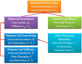
The further development of soft robotics and wearable robotics will be greatly accelerated by the availability of stretchable artificial muscles that can deliver biologically relevant forces, strokes, and speeds. This article has focused on an exciting new class of high-performance, stretchable artificial muscles made by twisting and coiling ordinary polymer fibers. The main aims of this article were to present the current state of understanding of the mechanisms of actuation operating in polymer coil muscles and to illustrate the connections between muscle performance and basic material properties. These parameters and relationships are schematically illustrated in Fig. 11. In all actuator materials and systems, the basic static performance is defined by the force and stroke generated when a given input stimulus is applied. These muscle outputs are affected by the external loading conditions, but more fundamentally by the actuation processes occurring within the actuator material. For simple linear elastic systems, the actuation performance is determined by the material stiffness (in the initial and final states) and the free stroke generated by the input stimulus.
Illustration of the main parameters and relationships that determine the performance of polymer coil artificial muscles.

The origin of the free stroke and actuator stiffness has been discussed for polymer coil muscles. As simple helically coils, the stiffnesses are well defined by classical spring mechanics where the fiber modulus and geometries of the coil and fiber are known to affect spring stiffness. It has been observed that the heat activation of polymer coil muscles has a small effect on the coil stiffness when heated over a narrow range (26–70 °C). In this case, the decrease in polymer modulus on heating appears to be offset by increases in fiber diameter.
Significant progress has been made recently in understanding the origin and magnitude of the free stroke occurring during heating of polymer coil muscles. It has been conclusively established that the tensile actuation stroke of polymer coil muscles is a direct result of untwisting torsional actuation in the fiber that forms the coil. Recent studies have focused on the mechanisms of torsional actuation in twisted fibers and other similar systems. Fiber untwist is associated with yarn or fiber volume increases and the single helix model has provided useful insight into this connection. In one study, the single helix model accurately predicted the torsional stroke of twisted nylon-6 fibers based on measured anisotropic volume change and by assuming that the ‘string length’ in the model remained unchanged. Further exploration of the single helix model shows that volume change anisotropy is important and the predominance of diameter expansion compared with length expansion in currently used twisted fiber muscles may be detrimental to torsional actuation.
Only limited studies have been conducted to date on polymer coil tensile actuators and twisted fiber torsional actuators. Polymer coil muscles have mostly been prepared by the over-twisting technique where the fiber twist and coil geometries are determined by the fiber diameter and modulus. Scaling analysis shows that such coiled muscles generate scale independent tensile strokes and volumetric work outputs. In addition, the tensile stroke is based on the torsional actuation which, in turn, is determined by the anisotropic volume expansion established by the oriented crystal structure.
Polymer coil muscles deliver impressive actuation performance characteristics, but further improvements may be possible based on the analyses presented here. Of particular practical significance is the need to increase the efficiency of conversion of electrical input energy to output mechanical energy, which is currently limited to less than 2%. Reference Haines, Lima, Li, Spinks, Foroughi, Madden, Kim, Fang, de Andrade, Goktepe, Goketpe, Mirvakili, Naficy, Lepro, Oh, Kozlov, Kim, Xu, Swedlove, Wallace and Baughman14 Two areas are suggested for further improving the work output of polymer coil muscles. Firstly, developing twisted fibers that generate favorable anisotropic volume expansion appears to be a powerful means for enhancing torsional stroke in twisted fibers and tensile stroke in coils made from such fibers. This suggestion is based on the untested extension of the single coil model to such systems. However, the success of the single helix model in predicting the torsional actuation of twisted nylon-6 fibers suggests that the model is more broadly applicable. The means for producing helically twisted fibers that expand mostly in the length direction rather than the diameter direction are yet to be determined. The ‘strings’ or ‘filaments’ that make up the helices in such systems must be inextensible so as to drive the torsional rotation during volume change.
The second suggested area for further work is to explore alternative coil geometries. The stroke and stiffness of the coils are strongly influenced by the coil diameter and coil bias angle. The analysis of work output suggests that coils formed from over-twisting may not produce the optimal work from a given length of twisted fiber. This area of investigation is completely unexplored at present.
ACKNOWLEDGMENTS
The author thanks Dharshika Kongahage and Dr. Sina Naficy for providing the experimental data of Figures 4 and 5. The author also thanks Professors Ray Baughman (University of Texas at Dallas), John D.W. Madden (University of British Columbia), and Seon Jeong Kim (Hanyang University) for valuable discussions. Financial support for this work was provided by the Australian Research Council (DP 110101073).