1. Introduction
When a strong shock wave propagates in a combustible medium, it can initiate exothermic chemical reactions in the medium if the temperature behind the shock is sufficiently high. In turn, when the energy released by the reactions supports the propagation of the shock wave, a self-sustained shock-reaction-zone regime exists and is called a detonation. The roots of the modern theory of detonation date back to the 1940s and the original studies of steady, one-dimensional detonation by Zel’dovich (Reference Zel’dovich1940), von Neumann (Reference von Neumann1942) and Döring (Reference Döring1943). The theory developed by these authors is now called the ZND theory. Subsequently, much experimental, theoretical and computational work has been performed to elucidate the complex, multi-dimensional and dynamical characteristics of detonations in gases and condensed explosives. The reader can learn about the present status of our understanding of many detonation phenomena in Lee (Reference Lee2008), Fickett & Davis (Reference Fickett and Davis2011) and Zhang (Reference Zhang2012).
Gaseous detonation waves can propagate in and be influenced by various geometric configurations. In large-diameter tubes, the propagation of detonation is usually in the form of a cellular detonation. A spinning or galloping detonation occurs in tubes of small diameter (Voitsekhovskii, Mitrofanov & Topchian Reference Voitsekhovskii, Mitrofanov and Topchian1966; Lee Reference Lee2008; Fickett & Davis Reference Fickett and Davis2011). In channels of rectangular cross-sections with various aspect ratios, similar cellular or galloping modes are also observed. In between parallel plates, when the gap between the plates is much smaller than the plates’ lateral span, a two-dimensional cellular detonation is observed because of the suppression of transverse waves in the direction normal to the plates (Soloukhin Reference Soloukhin1966; Voitsekhovskii et al. Reference Voitsekhovskii, Mitrofanov and Topchian1966).
In addition to these and similar configurations, which have extensively been studied since the 1950s, other configurations are those of detonations stabilized in supersonic flows, which are relevant to the problem of detonative propulsion and detonation engines. Extensive effort in the past has been expended on understanding detonations stabilized in supersonic flows. Research on this topic that began more than half a century ago and continues today is reviewed in several recent articles (e.g. Kailasanath Reference Kailasanath2000; Roy et al. Reference Roy, Frolov, Borisov and Netzer2004; Wolański Reference Wolański2013). The role played by the linear stability theory as well as asymptotic theories of detonation in understanding stability issues in propulsion systems is reviewed in Stewart & Kasimov (Reference Stewart and Kasimov2006).
In one configuration, a supersonic flow of a reactive mixture in a de Laval nozzle exits the nozzle and forms a Mach disk outside. The gas compression in the Mach disk initiates chemical reactions downstream so that a reaction zone forms at some distance from the disk. One of the early experimental studies of this flow configuration was reported in Nicholls & Dabora (Reference Nicholls and Dabora1961), where the authors were able to achieve a standing shock-reaction-zone complex. Even though this configuration resembles that of detonation, it is more properly called shock-induced combustion rather than detonation, because the Mach disk can exist stably in such a flow irrespective of the presence of chemical reactions. The extent to which the reaction zone plays a role in the existence and properties of the Mach disk appears not to have been explored in much detail, to the best of our knowledge.
More recent efforts to stabilize detonation in a supersonic flow can be found in e.g. Wintenberger & Shepherd (Reference Wintenberger and Shepherd2003), Wintenberger (Reference Wintenberger2004), Vasil’ev, Zvegintsev & Nalivaichenko (Reference Vasil’ev, Zvegintsev and Nalivaichenko2006) and Zhuravskaya & Levin (Reference Zhuravskaya and Levin2012). Wintenberger (Reference Wintenberger2004) carried out a detailed investigation of applications of detonative combustion to propulsion. In particular, issues arising in achieving a steady stabilized detonation in a supersonic flow were discussed. These include the necessity of using high-enthalpy flows of fuel–oxidizer mixture, careful control of expansion in the divergent part of the nozzle to avoid fuel condensation that occurs at low temperatures, control of the mixing distance to avoid premature combustion ahead of the detonation shock, etc. In Vasil’ev et al. (Reference Vasil’ev, Zvegintsev and Nalivaichenko2006), detonation in a supersonic flow in a channel was studied experimentally. A supersonic stream of a fuel–air mixture was generated with the help of high-pressure supply tanks pushing the fuel and oxidizer through a convergent–divergent nozzle into the test channel. Detonations running with and against the flow were studied and the effect of the flow boundary layers in the channel on the detonation velocity was investigated. In Zhuravskaya & Levin (Reference Zhuravskaya and Levin2012), stabilization by variation of the channel geometry was considered numerically using a model with multi-step kinetics for a hydrogen–air mixture. The authors concluded that variations of the channel cross-section can be used to stabilize the detonation wave in a channel.
Detonation can also be stabilized in a supersonic flow by a blunt body. The experiments that began in the 1950s by Gross and others are reviewed in e.g. Rubins & Bauer (Reference Rubins and Bauer1994); see also the more recent reviews mentioned above. In this configuration, the detonation is stabilized on a wedge in a supersonic stream of a reactive gas. Chemical reactions begin some distance downstream of the wedge nose and can influence the structure of the shock attached to the wedge. Similarly to the case of reactions downstream of the Mach disk in a de Laval nozzle, the shock in this experiment exists even in the absence of chemical reactions. Again, this configuration is more properly called shock-induced combustion.
Another popular and ingenious geometric configuration where detonation is stabilized in a supersonic flow by fixing its position in the axial direction, but allowing it to rotate in the azimuthal direction, is that of a continuously spinning detonation (Voitsekhovskii et al. Reference Voitsekhovskii, Mitrofanov and Topchian1966). Here, the supersonic stream of air enters a thin gap between two coaxial cylinders, mixes with the fuel injected from the inner cylinder, and continuously burns in a rotating detonation wave that propagates in the circumferential direction (Bykovskii, Mitrofanov & Vedernikov Reference Bykovskii, Mitrofanov and Vedernikov1997; Bykovskii, Zhdan & Vedernikov Reference Bykovskii, Zhdan and Vedernikov2006; Wolański Reference Wolański2013). This configuration is widely explored in designing detonation engines as an alternative to pulse-detonation engines.
Our goal here is to explore gaseous detonation in a new configuration wherein a supersonic stream of a combustible mixture emanates radially from a circular source and undergoes detonative combustion at some distance downstream. Such a flow configuration can be imagined to form between two parallel plates with an outside source of the mixture providing the inflow from the centre. Necessary high-speed flow conditions at the exit from such a source can be generated by rapid expansion through a nozzle-like configuration. However, irrespective of how such supersonic flow is generated (which is an interesting problem in itself, but is outside of the scope of this paper), the question of the existence and stability of a standing detonation wave downstream of such a flow is of interest and is the subject of the present study. We should note that detonation in this configuration is a self-sustained wave, as the existence of the shock wave depends on the presence of chemical reactions. In the absence of the latter, there would simply be an adiabatic expansion of the flow.
It is shown that the governing reactive Euler equations admit a steady-state solution with a self-sustained detonation standing at some finite distance from the source. Both the standard and a density-dependent one-step Arrhenius laws are used to describe the heat release. We analyse the nature of the steady-state solution by exploring the role of various parameters of the problem, such as the mixture properties and the inflow conditions. Using two-dimensional simulations, we investigate the nonlinear dynamics of the detonation, in particular its stability. We find that the detonation is unstable in all cases that we considered and that the instability exhibits itself not only in the form of cell formation, but also in the form of an overall radial contraction and expansion of the detonation front. We also find that the expansion can be prevented by putting several rigid obstacles downstream in the flow, which leads to a dynamically stabilized cellular detonation.
The rest of this paper is organized as follows. In § 2, we introduce the general formulation by explaining the geometry, governing equations and boundary conditions. In § 3, we analyse the steady-state radially symmetric solutions and their dependence on various parameters of the problem. In § 4, two-dimensional, time-dependent simulations are carried out to explore the multi-dimensional dynamics of the detonation in the given geometry. The paper concludes with a summary of the results in § 5.
2. Problem statement and governing equations
Consider a two-dimensional, radially symmetric supersonic flow of an ideal combustible gas emanating from a circular source of a given radius. In the absence of chemical reactions, the flow is adiabatic and, since it is also supersonic, during the expansion, the flow speed and the Mach number increase, while the pressure, temperature and density decrease with the distance from the source. These features can easily be established from basic equations of gas dynamics, as will be shown below. The main questions we address in this paper are the following. (i) Under what conditions can a steady radially symmetric detonation wave exist in such a radially expanding flow? (ii) If such a steady structure exists, is it stable to two-dimensional perturbations? We analyse the first question within the framework of ZND theory, while we investigate the second using numerical solutions of the two-dimensional reactive Euler equations with a single-step Arrhenius kinetics.
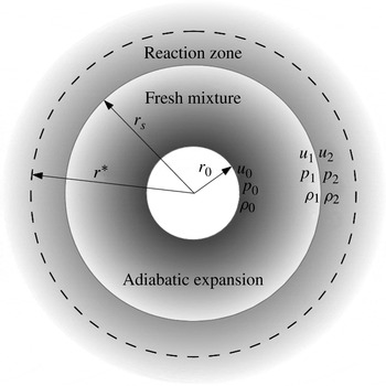
A schematic of the system is shown in figure 1, where one can see the central source of radius
 $r_{0}$
, from which the reactive gas emanates at initial flow conditions given by pressure,
 $p_{0}$
, density,
 ${\it\rho}_{0}$
and flow velocity,
 $u_{0}$
. Since the flow accelerates during supersonic expansion, at some distance from the centre,
 $r_{s}$
, the flow conditions can become such that a standing detonation wave structure can be established downstream of
 $r_{s}$
. Below, we show that such a detonation does indeed exist under a wide range of conditions. Moreover, we show the possibility of coexistence of multiple solutions under the same inflow conditions.
The geometry of the standing detonation in a radially expanding flow. The radius of the source is
 $r_{0}$
, the flow density at the source is
 ${\it\rho}_{0}$
, the pressure
 $p_{0}$
and the flow velocity
 $u_{0}$
. The standing detonation has radius
 $r_{s}$
, where the state in front of the detonation shock is
 ${\it\rho}_{1}$
,
 $p_{1}$
,
 $u_{1}$
and the state immediately behind the shock is
 ${\it\rho}_{2}$
,
 $p_{2}$
,
 $u_{2}$
. For the standing detonation, its velocity,
 $D$
, should be the same as
 $u_{1}$
. Behind the shock, there is a sonic locus at
 $r=r_{\ast }$
, where the flow velocity is equal to the local sound speed,
 $u_{\ast }=c_{\ast }$
.

If the temperature of the gas emanating from the source is sufficiently low, and since it decreases during the expansion, the flow from the source can be considered as adiabatic and reactions can be neglected. The detonation radius,
 $r_{s}$
, is unknown a priori, and it must be determined by matching the upstream state with the Rankine–Hugoniot conditions and the flow conditions downstream of the detonation shock. An important ingredient of such a detonation structure is the existence of a sonic point behind the shock. As explained below, the sonic point exists as a result of a balance between the flow acceleration caused by the chemical heat release and the deceleration caused by the expansion of the subsonic flow downstream of the detonation shock.
The velocity of gaseous detonation is usually of the order of a few kilometres per second and, to keep such a detonation at a fixed distance, the initial energy of the flow should be sufficiently high. We estimate the total energy of the initial flow that is necessary to establish the standing detonation. Assuming no friction losses, the total enthalpy of the flow,
 $$\begin{eqnarray}\mathscr{H}=\frac{{\it\gamma}}{{\it\gamma}-1}\frac{RT}{W}+\frac{u^{2}}{2},\end{eqnarray}$$
is a conserved quantity. Here,
 $T$
is the temperature of the flow,
 $u$
is the flow velocity,
 $W$
is the mixture molar mass,
 $R$
is the universal gas constant and
 ${\it\gamma}$
is the constant ratio of specific heats. During the adiabatic expansion, the temperature of the flow decreases; the flow velocity therefore increases. Even if all of the potential energy of the flow is converted to kinetic energy, the flow speed cannot be higher than
 $\sqrt{2\mathscr{H}}$
. On the other hand, the detonation velocity has its lower limit, which can be estimated by assuming that the radius of the converging detonation is much larger than the size of the reaction zone, and that we can neglect the detonation curvature effects and approximate the detonation velocity as
 $D_{CJ}=\sqrt{{\it\gamma}RT/W+Q({\it\gamma}^{2}-1)/2}+\sqrt{Q({\it\gamma}^{2}-1)/2}$
, where
 $T$
is the ambient temperature immediately ahead of the detonation shock and
 $Q$
is the heat release per unit mass of the mixture. Thus, the detonation velocity is always greater than
 $\sqrt{2Q({\it\gamma}^{2}-1)}$
. To keep the detonation at a fixed distance, the ambient flow has to accelerate to the detonation velocity, and hence the condition for the initial flow energy can be written as
 $\mathscr{H}>Q({\it\gamma}^{2}-1)$
. This requirement of high-enthalpy incoming flow necessary for the existence of a steady-state detonation solution (see also Wintenberger Reference Wintenberger2004) may require temperatures of the incoming mixture such that it may be incorrect to assume the state ahead of the detonation shock to be non-reactive. In principle, this problem may be overcome by mixing the fuel and oxidizer a short distance ahead of the detonation shock such that reactions have no time to begin before the gas runs into the shock (e.g. Rubins & Bauer Reference Rubins and Bauer1994). In practice, however, this is a challenging problem, especially in very high-speed flows in which mixing over short distances may be difficult to achieve.
2.1. Reactive Euler equations
We assume that the flow of a compressible reactive ideal gas is governed by the two-dimensional system of reactive Euler equations, describing conservation of mass, momentum and energy and the rate of chemical reaction, respectively,
 $$\begin{eqnarray}\displaystyle & \displaystyle \frac{\partial {\it\rho}}{\partial t}+\boldsymbol{{\rm\nabla}}\boldsymbol{\cdot }{\it\rho}\boldsymbol{u}=0, & \displaystyle\end{eqnarray}$$
 $$\begin{eqnarray}\displaystyle & \displaystyle \frac{\partial {\it\rho}\boldsymbol{u}}{\partial t}+\boldsymbol{{\rm\nabla}}\boldsymbol{\cdot }\left(p\unicode[STIX]{x1D644}+{\it\rho}\boldsymbol{u}\otimes \boldsymbol{u}\right)=0, & \displaystyle\end{eqnarray}$$
 $$\begin{eqnarray}\displaystyle & \displaystyle \frac{\partial {\it\rho}\mathscr{E}}{\partial t}+\boldsymbol{{\rm\nabla}}\boldsymbol{\cdot }\left({\it\rho}\boldsymbol{u}\left(\mathscr{E}+p/{\it\rho}\right)\right)=0, & \displaystyle\end{eqnarray}$$
 $$\begin{eqnarray}\displaystyle & \displaystyle \frac{\partial {\it\rho}{\it\lambda}}{\partial t}+\boldsymbol{{\rm\nabla}}\boldsymbol{\cdot }\left({\it\rho}\boldsymbol{u}{\it\lambda}\right)={\it\rho}{\it\omega}(p,{\it\rho},{\it\lambda}). & \displaystyle\end{eqnarray}$$
 $\mathscr{E}$
is the total energy,
 $\boldsymbol{u}$
is the velocity vector and
 ${\it\omega}(\,p,{\it\rho},{\it\lambda})$
is the rate of reaction assumed to follow a simplified model of the form
 $\text{Reactant}\rightarrow \text{Product}$
. The standard Arrhenius law,
 $$\begin{eqnarray}{\it\omega}=k\left(1-{\it\lambda}\right)\exp \left(-\frac{E{\it\rho}}{p}\right),\end{eqnarray}$$
is assumed in most of the calculations in this paper, where
 $E$
is the activation energy,
 ${\it\rho}$
is the density,
 $p$
is the pressure,
 $k$
is the reaction rate constant and
 ${\it\lambda}$
is the reaction-progress variable. We also consider the role of density dependence of the reaction rate in the steady-state structure and its instability (see §§ 3.2 and 4.4). The mass fraction of the reactant is
 $1-{\it\lambda}$
and that of the product is
 ${\it\lambda}$
, so that
 ${\it\lambda}=0$
corresponds to the fresh mixture and
 ${\it\lambda}=1$
to the fully burnt gas. The equation of state is given by
 $$\begin{eqnarray}e_{i}=\frac{1}{{\it\gamma}-1}\frac{p}{{\it\rho}}-{\it\lambda}Q,\end{eqnarray}$$
where
 ${\it\gamma}$
is the constant ratio of specific heats. The total energy in (2.4) is then defined as
 $\mathscr{E}=e_{i}+\boldsymbol{u}^{2}/2$
.
2.2. Shock conditions
The Rankine–Hugoniot shock conditions are
 $$\begin{eqnarray}\displaystyle & -D\left[{\it\rho}\right]+\left[{\it\rho}u_{n}\right]=0, & \displaystyle\end{eqnarray}$$
 $$\begin{eqnarray}\displaystyle & -D\left[{\it\rho}u_{n}\right]+\left[p+{\it\rho}u_{n}^{2}\right]=0, & \displaystyle\end{eqnarray}$$
 $$\begin{eqnarray}\displaystyle & -D\left[{\it\rho}\mathscr{E}\right]+\left[u_{n}\left({\it\rho}\mathscr{E}+p\right)\right]=0, & \displaystyle\end{eqnarray}$$
 $$\begin{eqnarray}\displaystyle & -D\left[{\it\rho}{\it\lambda}\right]+\left[{\it\rho}u_{n}{\it\lambda}\right]=0, & \displaystyle\end{eqnarray}$$
 $[\,z\,]$
denotes the jump of variable
 $z$
across the shock, i.e. the value of
 $z$
immediately in front of the shock minus its value immediately behind,
 $D$
is the normal component of the shock speed and
 $u_{n}$
is the normal component of the flow velocity. As usual, the shock itself is non-reactive; hence, (2.11) is satisfied trivially. In a steady-state detonation, the detonation velocity is equal to the ambient flow velocity, i.e.
 $D=u_{1}$
, such that, in the laboratory frame of reference, the detonation is stationary. For the circular steady-state solution, the flow is perpendicular to the shock front. For an ideal gas, the Rankine–Hugoniot conditions can therefore be written as
 $$\begin{eqnarray}\displaystyle & {\it\rho}_{1}u_{1}={\it\rho}_{2}u_{2}, & \displaystyle\end{eqnarray}$$
 $$\begin{eqnarray}\displaystyle & p_{2}+{\it\rho}_{2}u_{2}^{2}=p_{1}+{\it\rho}_{1}u_{1}^{2}, & \displaystyle\end{eqnarray}$$
 $$\begin{eqnarray}\displaystyle & \displaystyle \frac{{\it\gamma}}{{\it\gamma}-1}\frac{p_{1}}{{\it\rho}_{1}}+\frac{u_{1}^{2}}{2}=\frac{{\it\gamma}}{{\it\gamma}-1}\frac{p_{2}}{{\it\rho}_{2}}+\frac{u_{2}^{2}}{2}, & \displaystyle\end{eqnarray}$$
 ${\it\rho}_{1},u_{1},\,p_{1}$
and
 ${\it\rho}_{2},u_{2},\,p_{2}$
are the pre-shock and post-shock density, velocity and pressure, respectively. From these equations, the post-shock state can be written explicitly in terms of the pre-shock state.
In the next section, we show that the steady-state system is reduced to two ordinary differential equations (ODEs) for
 $u$
and
 ${\it\lambda}$
and two conservation laws for the total energy and mass. We assume that the reaction rate is zero in the upstream flow, which allows us to use the Rankine–Hugoniot condition only for the flow velocity, which takes a very simple form:
 $$\begin{eqnarray}u_{1}u_{2}=2\frac{{\it\gamma}-1}{{\it\gamma}+1}\mathscr{H},\end{eqnarray}$$
where
 $\mathscr{H}={\it\gamma}p_{0}/(({\it\gamma}-1){\it\rho}_{0})+u_{0}^{2}/2$
is the total enthalpy at the source, which in the steady state is conserved along the flow.
2.3. Dimensionless equations and the choice of parameters
In problems where detonation propagates into a quiescent state of constant parameters, it is natural to scale the variables with respect to that constant state or with respect to the post-shock state, the latter usually being done in linear stability studies. In our problem, the detonation stands or propagates in a non-uniform medium and, for that reason, the best choice of scales is not completely obvious. We have decided to choose some reference pressure,
 $p_{a}$
, reference density,
 ${\it\rho}_{a}$
, temperature,
 $T_{a}=Wp_{a}/{\it\rho}_{a}$
, and velocity,
 $u_{a}=\sqrt{p_{a}/{\it\rho}_{a}}$
. These can be taken as corresponding to the standard case of 1 atm and 300 K, as we do here. Whatever the choice of such a reference state, and with the choice of length and time scales as explained below, the governing equations retain their form. While it may seem more natural to choose the state immediately ahead of the detonation shock as a reference scale, note that this state is unknown a priori because the shock position is unknown a priori. We therefore do not consider this choice.
The remaining scales are that of length, for which we choose the standard half-reaction-zone length,
 $l_{1/2}$
, for a planar detonation that propagates into the above reference state, and the time scale,
 $t_{1/2}=l_{1/2}/u_{a}$
. For any given reaction parameters,
 $Q$
,
 $E$
and
 ${\it\gamma}$
, setting these scales amounts to fixing the rate constant by the integral
 $$\begin{eqnarray}k=\int _{0}^{1/2}\frac{U({\it\lambda})\text{d}{\it\lambda}}{\left(1-{\it\lambda}\right)\exp \left(-E/T({\it\lambda})\right)},\end{eqnarray}$$
where
 $D_{CJ}=\sqrt{{\it\gamma}+({\it\gamma}^{2}-1)Q/2}+\sqrt{({\it\gamma}^{2}-1)Q/2}$
and
 $$\begin{eqnarray}\displaystyle U({\it\lambda}) & = & \displaystyle \frac{{\it\gamma}}{{\it\gamma}+1}\left[\left(D_{CJ}+D_{CJ}^{-1}\right)\right.\nonumber\\ \displaystyle & & \displaystyle \left.-\,\sqrt{\left(D_{CJ}+D_{CJ}^{-1}\right)^{2}-\frac{2\left({\it\gamma}^{2}-1\right)}{{\it\gamma}^{2}}\left(\frac{{\it\gamma}}{{\it\gamma}-1}+\frac{1}{2}D_{CJ}^{2}+Q{\it\lambda}\right)}\right],\end{eqnarray}$$
 $$\begin{eqnarray}\displaystyle T({\it\lambda}) & = & \displaystyle \frac{{\it\gamma}-1}{{\it\gamma}}\left(\frac{{\it\gamma}}{{\it\gamma}-1}+\frac{1}{2}D_{CJ}^{2}+Q{\it\lambda}-\frac{1}{2}U({\it\lambda})^{2}\right).\end{eqnarray}$$
Thus, in all calculations below, the length and time scales are determined by
 $k$
, which varies depending on the values of
 $Q,E$
and
 ${\it\gamma}$
based on the dimensionless upstream state of
 $p=1$
,
 ${\it\rho}=1$
and
 $T=1$
.
3. The steady-state, radially symmetric solution
In the steady-state, radially symmetric case, the equations of motion become
 $$\begin{eqnarray}\displaystyle & \displaystyle \frac{1}{r}\frac{\text{d}}{\text{d}r}\left(r{\it\rho}u\right)=0, & \displaystyle\end{eqnarray}$$
 $$\begin{eqnarray}\displaystyle & \displaystyle \frac{\text{d}}{\text{d}r}(p+{\it\rho}u^{2})+\frac{{\it\rho}u^{2}}{r}=0, & \displaystyle\end{eqnarray}$$
 $$\begin{eqnarray}\displaystyle & \displaystyle \frac{1}{r}\frac{\text{d}}{\text{d}r}\left(r{\it\rho}u\left(\mathscr{E}+p/{\it\rho}\right)\right)=0, & \displaystyle\end{eqnarray}$$
 $$\begin{eqnarray}\displaystyle & \displaystyle \frac{1}{r}\frac{\text{d}}{\text{d}r}\left(r{\it\rho}u{\it\lambda}\right)={\it\rho}{\it\omega}(\,p,{\it\rho},{\it\lambda}). & \displaystyle\end{eqnarray}$$
 $u$
and
 ${\it\lambda}$
,
 $$\begin{eqnarray}\displaystyle & \displaystyle \frac{\text{d}u}{\text{d}r}=\frac{\left({\it\gamma}-1\right)Q{\it\omega}-uc^{2}/r}{c^{2}-u^{2}}, & \displaystyle\end{eqnarray}$$
 $$\begin{eqnarray}\displaystyle & \displaystyle \frac{\text{d}{\it\lambda}}{\text{d}r}=\frac{{\it\omega}}{u}, & \displaystyle\end{eqnarray}$$
 $$\begin{eqnarray}\displaystyle & r{\it\rho}u=\mathscr{M}=\text{const.}, & \displaystyle\end{eqnarray}$$
 $$\begin{eqnarray}\displaystyle & \displaystyle \frac{c^{2}}{{\it\gamma}-1}-{\it\lambda}Q+\frac{u^{2}}{2}=\mathscr{H}=\text{const.} & \displaystyle\end{eqnarray}$$
 $c=\sqrt{{\it\gamma}p/{\it\rho}}$
is the local speed of sound,
 $r$
is the radial coordinate and
 $\mathscr{M}$
is the mass flux. In the computations below, we rewrite (3.5) and (3.6) as an autonomous system of three equations where the unknowns are parameterized by
 ${\it\tau}$
:
 $$\begin{eqnarray}\frac{\text{d}u}{\text{d}{\it\tau}}=u\frac{\left({\it\gamma}-1\right)Q{\it\omega}-uc^{2}/r}{c^{2}-u^{2}},\quad \frac{\text{d}r}{\text{d}{\it\tau}}=u,\quad \frac{\text{d}{\it\lambda}}{\text{d}{\it\tau}}={\it\omega}.\end{eqnarray}$$
This system and two conservation laws for the mass and enthalpy, (3.7) and (3.8), together with the boundary conditions at the source and in the far field and the shock condition (2.15) fully determine the standing detonation structure. The parameterization in (3.9) is introduced for the purpose of its numerical integration. From the second equation in (3.9b),
 ${\it\tau}$
is seen to be a time-like variable.
The ambient state between the source and the detonation shock is in an adiabatic expansion. The steady-state equations there reduce to one algebraic equation, for example, for the flow velocity:
 $$\begin{eqnarray}r=r_{0}\frac{u_{0}}{u}\left(\frac{\mathscr{H}-u_{0}^{2}/2}{\mathscr{H}-u^{2}/2}\right)^{1/\left({\it\gamma}-1\right)},\end{eqnarray}$$
where
 $r_{0}$
is the radius of the source and
 $u_{0}$
is the flow velocity at the source. This result follows simply by using (3.7) and (3.8) with
 ${\it\lambda}=0$
and the direct integration of (3.5). The latter is possible because it is assumed that
 ${\it\omega}=0$
upstream.
The form of (3.5), wherein there is a possibility of a sonic point in the flow, where
 $u=c$
, and a possibility of regularization by setting the numerator of (3.5) to zero at the same point, gives the existence conditions for the solution. In principle, the solution procedure requires one to find the whole structure for given inflow conditions. However, neither the shock location, nor the location of the sonic point can be directly calculated. An iterative procedure is needed to determine them.
It is important, from a physical point of view, to note that the steady-state solution in this converging shock geometry is possible because of the flow divergence present in the flow entering the shock. The streamlines remain diverging behind the circular shock. Therefore, the flow deceleration in the subsonic diverging flow behind the shock can be balanced by the flow acceleration caused by the chemical heat release. This is an important distinction from the more standard situations where the pre-shock state is a uniform parallel flow relative to the shock. In the latter case, the streamlines behind the converging shock would converge and thus the post-shock flow would accelerate because of that; there would be no competition between the heat release and the flow divergence (convergence in this case), hence there would be no steady-state solution.
Since the sonic locus is a saddle point, it is numerically more robust to find the solution in the neighbourhood of the sonic point as a Taylor series expansion, and then to step away from it and continue integrating by a regular numerical method. Such an approach is standard in, for example, detonation shock dynamics (DSD) theory (Bdzil & Stewart Reference Bdzil, Stewart and Zhang2012). The sonic-point position in our case is unknown explicitly. When the boundary conditions are fixed at the source, system (3.9) has one guessing parameter at the sonic point. It can be the radius of the sonic point,
 $r_{\ast }$
, the radius of the detonation,
 $r_{s}$
, or the value of the reaction progress variable at the sonic point,
 ${\it\lambda}_{\ast }$
. To satisfy the boundary conditions at the source, we can scan one of these parameters, for example,
 ${\it\lambda}_{\ast }$
.
To illustrate the algorithm, suppose that the source has radius
 $r_{0}$
, and the flow at the source has pressure
 $p_{0}$
, density
 ${\it\rho}_{0}$
and supersonic flow velocity
 $u_{0}>c_{0}$
. Once the flow at the source is known, we can calculate
 $\mathscr{H}$
and
 $\mathscr{M}$
, which are conserved in the whole domain. Since
 $\mathscr{H}$
is fixed, we can write the expression for the radius of the sonic point,
 $r_{\ast }$
, as a function of
 ${\it\lambda}_{\ast }$
by setting the numerator of (3.9a) to zero and using
 $c_{\ast }=u_{\ast }$
:
 $$\begin{eqnarray}r_{\ast }\left({\it\lambda}_{\ast }\right)=\frac{c_{\ast }^{3}}{\left({\it\gamma}-1\right){\it\omega}_{\ast }Q}.\end{eqnarray}$$
Here, the reaction rate and the speed of sound depend only on
 ${\it\lambda}_{\ast }$
through the following expressions:
 $$\begin{eqnarray}\displaystyle & {\it\omega}_{\ast }={\it\omega}\left({\it\lambda}_{\ast }\right)=k\left(1-{\it\lambda}_{\ast }\right)\exp \left(-{\it\gamma}E/c_{\ast }^{2}\right), & \displaystyle\end{eqnarray}$$
 $$\begin{eqnarray}\displaystyle & \displaystyle c_{\ast }=c\left({\it\lambda}_{\ast }\right)=u_{\ast }=\sqrt{\frac{2\left({\it\gamma}-1\right)\left(\mathscr{H}+{\it\lambda}_{\ast }Q\right)}{{\it\gamma}+1}}. & \displaystyle\end{eqnarray}$$
The value of
 ${\it\lambda}_{\ast }$
is a guessing parameter in this algorithm, and by scanning it between 0 and 1, the initial conditions at the source can be satisfied. Once
 ${\it\lambda}_{\ast }$
is fixed, and since
 $\mathscr{H}$
is known, we can integrate (3.9) up to a point where the mixture becomes fresh, i.e.
 ${\it\lambda}({\it\tau}_{s})=0$
. This point defines the beginning of the reaction zone, which is the post-shock state. Therefore, the radius of the shock is given by
 $r_{s}=r({\it\tau}_{s})$
. Subsequently, by applying the shock condition (2.15), we can easily obtain the state ahead of the shock and all the adiabatic profiles by evaluation of (3.10).
Simple analysis shows that the steady-state detonation solution may exist only for a certain range of the initial parameters at the source. Consider the scanning procedure from another point of view. Let us assume that
 $\mathscr{H}$
is fixed. Then we solve (3.9) for the range of values of the reaction progress variable at the sonic point,
 $0<{\it\lambda}_{\ast }<1$
. These solutions give the dependence of the post-shock flow velocity on the detonation radius,
 $u_{2}^{d}(r_{s})$
, and this function is monotonically decreasing and convex. The same dependence can be calculated for the adiabatic expansion using (2.15) and (3.10). The latter curve is also convex and monotonically decreasing, but it contains one additional parameter, the initial flow velocity at the source,
 $u_{2}^{a}(r_{s},u_{0})$
. Then, adjusting
 $u_{0}$
, we can shift the adiabatic curve,
 $u_{2}^{a}(r_{s},u_{0})$
, with respect to the detonation curve,
 $u_{2}^{d}(r_{s})$
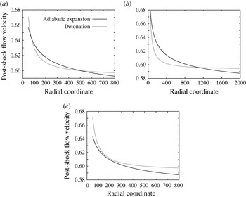
. At some values of the initial flow velocity, the curves intersect, implying the existence of a solution. These curves may have up to two intersection points (figure 2
a), which gives the existence of multiple steady-state solutions for the particular flow at the source. The absence of intersection points means the non-existence of a steady-state solution to the problem (figure 2
c).
The intersecting curves,
 $u_{2}^{d}(r_{s})$
and
 $u_{2}^{a}(r_{s},u_{0})$
, when there are two, one and no intersections. The parameters of the mixture are:
 ${\it\gamma}=1.2$
,
 $E=40$
,
 $Q=30$
,
 $\mathscr{H}=1.3\mathscr{H}_{min}$
,
 $r_{0}=50$
. (a)
 $M_{0}=4.40$
, (b)
 $M_{0}=4.0$
and (c)
 $M_{0}=4.67$
.

An important consequence of the discussion above is that the radius of detonation for a particular mixture depends only on two parameters: the value of the total enthalpy of the flow and the value of the initial flow velocity. At some values of these parameters, the solution may not exist and at other values, one or two solutions are possible.
3.1. Existence and structure of the steady-state solution
Here, we explore the role played by the mixture properties as well as the inflow conditions at the source in the structure of the steady-state solution. The essential problem is to identify when the solution exists and, if it does, where the detonation is located.
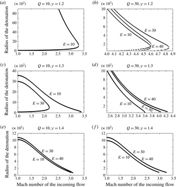
In figure 3, we show how the Mach number of the incoming flow affects the detonation radius at a fixed radius of the source and a fixed value of the stagnation enthalpy. The figures also display the role played by the activation energy,
 $E$
, heat release,
 $Q$
and the specific-heat ratio,
 ${\it\gamma}$
. The existence of a relatively small radius and a relatively large radius is typical in these figures. At
 ${\it\gamma}=1.2$
, we see that increasing
 $Q$
requires larger values of
 $M_{0}$
in order to achieve a stationary solution. At the same time, the upper radius decreases by an order of magnitude from more than 9000 to approximately 1000 when
 $Q$
is changed from 10 to 30. This indicates that provided that the Mach number of the incoming flow is large enough, it is feasible to have a detonation whose radius is about a factor of 1000 larger than the size of the reaction zone. Increasing
 ${\it\gamma}$
has an interesting effect of not only reducing the upper radius of detonation to about the same factor of 1000 reaction zones, but also reducing the Mach number of the incoming flow significantly, from approximately 3–5 for
 ${\it\gamma}=1.2$
down to 1–3. It is worth noting that the effect of the activation energy is non-monotone, i.e. as the activation energy is increased, the detonation radius may first increase and then decrease. An interesting case is represented in figure 3(c) at
 $E=30$
. Even at the source Mach number of 1, there exist two solutions, the lower radius being about
 $r_{s}=100$
and the upper approximately 3000. We point out here that the existence of multiple steady-state solutions is common in detonation problems with various loss effects, such as the flow divergence (Bdzil & Stewart Reference Bdzil, Stewart and Zhang2012) or frictional and heat losses (Zel’dovich & Kompaneets Reference Zel’dovich and Kompaneets1960).
The detonation radius,
 $r_{s}$
, as a function of the source-flow Mach number,
 $M_{0}$
, for various
 $E$
,
 $Q$
, and
 ${\it\gamma}$
. The radius of the source is
 $r_{0}=50$
and the stagnation enthalpy is
 $\mathscr{H}=1.3\mathscr{H}_{min}=1.3Q({\it\gamma}^{2}-1)$
.

If the mixture enthalpy,
 $\mathscr{H}$
, is small, i.e. close to the minimum value of
 $\mathscr{H}_{min}=Q({\it\gamma}^{2}-1)$
, then the energy is insufficient to accelerate the flow to high speeds even all the way to infinity. Then, the top branch of the
 $r_{s}{-}M_{0}$
curve is absent, but the bottom branch still exists. If on the other hand,
 $\mathscr{H}$
is very high, the top branch is feasible, but the bottom branch disappears. The reason for this is that the corresponding radius becomes smaller than the source radius. These are the reasons for the absence of the bottom branch of some of the curves in figure 3.
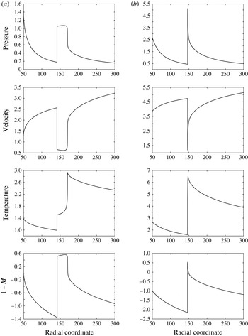
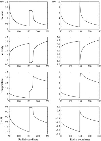
It is of interest to explore the structure of the steady-state solutions corresponding to the upper and lower solutions shown in figure 3. In figure 4, we plot the profiles of
 $p$
,
 $u$
,
 $T$
and
 $1-M$
that correspond to the lower solution (figure 4
a) and to the upper solution (figure 4
b) under similar flow conditions. The most distinctive feature of the solution shown in figure 4(a) is a square-wave-like structure with a rather long reaction zone. The profiles of pressure, temperature, velocity and Mach number are seen to exhibit almost constant states behind the shock until a thin region of the energy release. There is a clear induction zone that extends some 30 length units. Subsequently, all of the energy is released over the distance of a few length units. In contrast, the structure for the upper solution has no induction zone, and the reaction zone is sharp, spanning only few length units (figure 4
b). The mixture properties for these two cases are the same, except for
 ${\it\gamma}$
. The inflow conditions were chosen differently to place the detonation at about the same distance from the origin in both cases. Therefore, one can modify the inflow conditions so that two very different types of standing detonation can exist at the same radius. Clearly, their stability is a deciding factor in whether such detonations persist or not, but here we limit the discussion of the existence of solutions to the steady-state equations. Stability is investigated in the subsequent sections. These two types of the steady-state solution structures are chosen to illustrate their qualitative differences and dynamical properties. All intermediate structures and therefore intermediate dynamical properties are also possible.
Two types of steady-state detonation profiles. (a) The square-wave detonation on a lower branch of the
 $r_{s}{-}M$
curve, when two branches exist; for both of them, the solution takes a square-wave shape. For (b), only the upper branch exists. The parameters are: (a)
 ${\it\gamma}=1.2$
,
 $Q=10$
,
 $E=30$
,
 $r_{0}=50$
,
 ${\it\rho}_{0}=1$
,
 $p_{0}=1.40$
,
 $u_{0}=1.30$
,
 $M_{0}=1.0$
and
 $\mathscr{H}=2.1\mathscr{H}_{min}$
; (b)
 ${\it\gamma}=1.4$
,
 $Q=10$
,
 $E=30$
,
 $r_{0}=50$
,
 ${\it\rho}_{0}=1$
,
 $p_{0}=2.70$
,
 $u_{0}=3.90$
,
 $M_{0}=2.0$
and
 $\mathscr{H}=1.75\mathscr{H}_{min}$
.

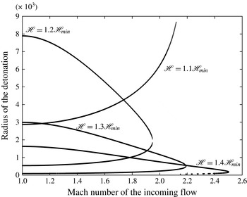
In the preceding calculations, the inflow enthalpy is fixed and the role of mixture parameters and the inflow Mach number is explored. Now, we investigate the effect of the inflow enthalpy and the inflow Mach number on the detonation radius for a given mixture. The result is displayed in figure 5. It is found that increasing the mixture enthalpy brings the upper solution to lower values of the detonation radius. The radius of the lower solution also decreases as
 $\mathscr{H}$
increases. This result is consistent with the expectation that the higher the enthalpy of the flow, the easier it is to accelerate it to velocities necessary to establish a steady-state detonation in the flow.
The radius of detonation as a function of the Mach number of the initial flow for different values of the stagnation enthalpy,
 $\mathscr{H}$
. The mixture parameters are
 ${\it\gamma}=1.3$
,
 $Q=10$
and
 $E=30$
. The radius of the source is
 $r_{0}=50$
.

To proceed with the exploration of the parameter space, we next identify the regions of the
 $Q$
–
 $E$
space for which a detonation solution exists at a given
 $M_{0}$
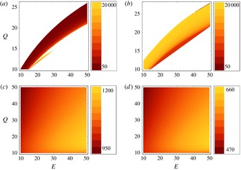
. In figure 6, we display the minimal radius of detonation as a function of
 $Q$
and
 $E$
for two different inflow Mach numbers,
 $M_{0}=1$
and
 $M_{0}=2$
at
 ${\it\gamma}=1.2$
and
 ${\it\gamma}=1.4$
. What is interesting in these figures is that for the larger
 ${\it\gamma}=1.4$
, the range of solutions is much wider and the minimal radius is much smaller than in the case of
 ${\it\gamma}=1.2$
.
The minimal detonation radius as a function of
 $E$
and
 $Q$
: (a,b)
 ${\it\gamma}=1.2$
and (c,d)
 ${\it\gamma}=1.4$
; (a,c)
 $M_{0}=1$
and (b,d)
 $M_{0}=2$
. The radius of the source is
 $r_{0}=50$
and
 $\mathscr{H}=1.3\mathscr{H}_{min}$
.

The radius of the converging detonation depends on the flow at the source and on the mixture parameters. To find this dependence, we should solve the full system (3.9) for the range of these parameters. Before solving this problem, certain analytical estimates can be made. For a standing detonation, the flow velocity at some point should equal the detonation velocity, i.e.
 $u_{1}=D$
. The detonation velocity, when the detonation radius is large, can be estimated by the Chapman–Jouguet (CJ) formula:
 $$\begin{eqnarray}D_{CJ}=\sqrt{{\it\gamma}T+{\textstyle \frac{1}{2}}Q({\it\gamma}^{2}-1)}+\sqrt{{\textstyle \frac{1}{2}}Q({\it\gamma}^{2}-1)},\end{eqnarray}$$
where
 $T$
is the temperature immediately ahead of the detonation shock. As long as the enthalpy is fixed, the ambient temperature for the adiabatic expansion is a function only of the flow velocity,
 $$\begin{eqnarray}T=\frac{{\it\gamma}-1}{{\it\gamma}}\left(\mathscr{H}-\frac{u^{2}}{2}\right),\end{eqnarray}$$
and, therefore, we can write the following equation for the adiabatic flow velocity at the detonation-shock position:
 $$\begin{eqnarray}u_{1}=\sqrt{\left({\it\gamma}-1\right)\left(\mathscr{H}-{\textstyle \frac{1}{2}}u_{1}^{2}\right)+{\textstyle \frac{1}{2}}Q\left({\it\gamma}^{2}-1\right)}+\sqrt{{\textstyle \frac{1}{2}}Q\left({\it\gamma}^{2}-1\right)}.\end{eqnarray}$$
This equation can be solved for
 $u_{1}$
, and its solution together with (3.10) gives the dependence of the detonation radius on the initial flow velocity, i.e.
 $r_{s}(u_{0})$
. This function decays monotonically: the faster the flow at the source, the sooner it reaches the CJ velocity,
 $D_{CJ}$
. This estimate gives a reasonably accurate description of the top branch of the
 $r_{s}{-}M_{0}$
curve.
3.2. The effect of the density-dependent rate function
The previous calculations employ the standard simple-depletion Arrhenius kinetics which is widely used in basic modelling and theoretical studies of detonations. It is of interest to explore which changes to the theory, if any, are brought about by other rate functions. Obviously, in order to be as close to realistic situations as possible, one must employ more complex, multi-step chemical mechanisms for reactions together with appropriate complex thermodynamic descriptions of the mixture. While such an extension is outside the scope of the present work, we next consider a simple modification of the Arrhenius law that appears to give somewhat more realistic predictions for detonation behaviour than the standard rate law. The modified reaction model is expected to lead to some additional effects. However, the basic observations described above for the simplest rate function still hold true. We illustrate this point below using the following modified Arrhenius rate function with an additional density factor:
 $$\begin{eqnarray}{\it\omega}=k{\it\rho}\left(1-{\it\lambda}\right)\exp \!\left(-\frac{E{\it\rho}}{p}\right),\end{eqnarray}$$
where
 $k$
is found as before from the half-reaction-length conditions for the one-dimensional detonation. This modification of the standard Arrhenius law is known to affect some of the details of detonation dynamics (Khasainov & Veyssiere Reference Khasainov and Veyssiere2013).
The governing equations of the steady-state structure and the algorithm of their solution are essentially the same as before. The regularization conditions at the sonic point yield the following algebraic equation for the flow velocity at the sonic point for the given stagnation enthalpy,
 $\mathscr{H}$
, and mass flux,
 $\mathscr{M}$
:
 $$\begin{eqnarray}k\mathscr{M}\left(1-\frac{1}{Q}\left(\frac{{\it\gamma}-1}{{\it\gamma}+1}\frac{u_{\ast }^{2}}{2}-\mathscr{H}\right)\right)\exp \!\left(-\frac{{\it\gamma}E}{u_{\ast }^{2}}\right)=u_{\ast }^{4}.\end{eqnarray}$$
This equation can in general have two solutions. We see that the presence of the density dependence in the rate function eliminates the radius of the sonic point from the regularization condition resulting in a universal function,
 $u({\it\lambda})$
, for the fixed enthalpy and mass flux. The solution of (3.5) and (3.6) in the neighbourhood of the sonic point can be found as a linear approximation,
 $u=u_{\ast }-a{\rm\Delta}r$
,
 ${\it\lambda}={\it\lambda}_{\ast }-b{\rm\Delta}r$
and
 $r=r_{\ast }-{\rm\Delta}r$
, where
 ${\rm\Delta}r$
is a fixed small spatial step out from the sonic point. Substitution of these expansions into the governing system of ODEs gives two algebraic equations for
 $a>0$
and
 $b>0$
. Once
 $a$
and
 $b$
are found, we integrate the ODE to the von Neumann point, where
 ${\it\lambda}=0$
. Using the shock conditions and the algebraic formula for the adiabatic flow, we can then evaluate the solution up to the source,
 $r_{0}$
.
The new steady-state profiles are shown in figure 7. With the chosen parameters, these solutions are seen to be qualitatively similar to those with the standard Arrhenius function. The choice of parameters is made so as to illustrate the difference in the two-dimensional dynamics in the simulations below when the underlying steady-state structures are nearly the same for both the standard and modified rate functions. We keep the same mixture properties, the same radius of the source, the same Mach number at the source and nearly the same radius of the steady-state detonation,
 $r_{s}$
, as in the standard Arrhenius case.
Two types of steady-state detonation profiles for the modified rate function, (3.17): (a)
 ${\it\gamma}=1.2$
,
 $Q=10$
,
 $E=30$
,
 $r_{0}=50$
,
 ${\it\rho}_{0}=1.51$
,
 $p_{0}=2.42$
,
 $u_{0}=1.38$
and
 $M_{0}=1.0$
; (b)
 ${\it\gamma}=1.4$
,
 $Q=10$
,
 $E=30$
,
 $r_{0}=50$
,
 ${\it\rho}_{0}=3.65$
,
 $p_{0}=12.52$
,
 $u_{0}=3.58$
and
 $M_{0}=2.0$
.

4. Two-dimensional simulations
Even though the steady-state solutions exist for a wide range of parameters of the problem, it is important to understand their stability. Gaseous detonations are almost always unstable to multi-dimensional perturbations and we expect instability in our case as well. However, two novel elements of the configuration at hand will play roles and must be elucidated, namely the non-uniform flow upstream of the detonation shock and the curvature of the detonation shock.
Based on the following simple argument, one might conclude that, in fact, the detonation in our configuration should always be unstable even with respect to longitudinal perturbations. Consider a steady-state radially symmetric detonation standing at some distance from the centre, and imagine that it is perturbed a small distance inward toward the source. Then, because the upstream flow after the perturbation is slower than before the perturbation, and because detonation tends to propagate at a constant speed relative to the flow upstream, the perturbed shock continues to move inward, which implies instability. In the opposite situation of the detonation shock perturbed outward, the flow upstream of the perturbed shock is faster than that before the perturbation. Hence, for the same reason that detonation tends to propagate with a constant speed relative to the upstream state, the perturbed shock will continue expanding, again implying instability.
The previous arguments can be made more formal by the following considerations (Zhang et al.
Reference Zhang, Chue, Frost, Lee, Thibault and Yee1995; Wintenberger Reference Wintenberger2004). Suppose that the detonation shock is located at
 $r_{s}$
and its speed relative to the upstream flow is approximated by
 $D_{CJ}(r_{s})$
, the CJ speed for the upstream adiabatic flow at
 $r_{s}$
. Then, in the laboratory frame of reference, the shock speed is given by
 $U_{CJ}=u_{1}(r_{s})-D_{CJ}(r_{s})$
, where
 $u_{1}$
is the velocity of the adiabatic flow at
 $r_{s}$
. Clearly, in the steady state,
 $U_{CJ}=0$
.
Now suppose that this shock is perturbed to a new position,
 $r_{s}+{\it\delta}$
, by a small distance,
 ${\it\delta}$
. Then, the new relative velocity becomes
 $$\begin{eqnarray}U_{CJ}(r_{s}+{\it\delta})=u_{1}(r_{s}+{\it\delta})-D_{CJ}(r_{s}+{\it\delta})=\frac{\partial U_{CJ}}{\partial r_{s}}{\it\delta}+O({\it\delta}^{2}).\end{eqnarray}$$
Thus, if
 $\partial U_{CJ}/\partial r_{s}>0$
, then the relative velocity becomes positive for
 ${\it\delta}>0$
and negative for
 ${\it\delta}<0$
, implying that the equilibrium position is unstable. In the opposite case, the equilibrium is stable.
To evaluate the sign of
 $\partial U_{CJ}/\partial r_{s}$
, we use the adiabatic flow solution, (3.10), and the CJ formula for the detonation speed,
 $D_{CJ}=\sqrt{c_{1}^{2}+q}+\sqrt{q}$
, where
 $q=({\it\gamma}^{2}-1)$
 $Q/2$
and
 $c_{1}$
is the sound speed at
 $r_{s}$
, just ahead of the detonation shock. Using also
 $c_{1}^{2}/({\it\gamma}-1)+u_{1}^{2}/2=\text{const.}$
, we find that
 $$\begin{eqnarray}\frac{\partial D_{CJ}}{\partial r_{s}}=-\frac{{\it\gamma}-1}{2\sqrt{c_{1}^{2}+q}}u_{1}\frac{\partial u_{1}}{\partial r_{s}}.\end{eqnarray}$$
Therefore,
 $$\begin{eqnarray}\frac{\partial U_{CJ}}{\partial r_{s}}=\left[1+\frac{{\it\gamma}-1}{2\sqrt{c_{1}^{2}+q}}u_{1}\right]\frac{\partial u_{1}}{\partial r_{s}},\end{eqnarray}$$
and the sign of
 $\partial u_{1}/\partial r_{s}$
determines the stability behaviour. Taking the logarithm of (3.10) and then differentiating the result with respect to
 $u_{1}$
, we find that
 $$\begin{eqnarray}\frac{1}{r_{s}}\frac{\partial r_{s}}{\partial u_{1}}=\frac{M_{1}^{2}-1}{u_{1}},\end{eqnarray}$$
where
 $M_{1}=u_{1}/c_{1}$
is the Mach number of the adiabatic flow just upstream of the detonation shock. Since
 $M_{1}>1$
, we see that
 $\partial u_{1}/\partial r_{s}>0$
and hence
 $\partial U_{CJ}/\partial r_{s}>0$
, implying unconditional – within the assumptions used above – instability with respect to the radial displacement of the detonation shock.
Despite the dramatic appearance of the conclusion just reached, the existence of the steady-state solution by itself is of much significance. The importance of the steady-state solution, irrespective of its stability properties, lies in its being an equilibrium (or a fixed) point of the underlying system of time-dependent governing equations. Even if the fixed point is unstable, an initial value problem with initial conditions in a small neighbourhood of the fixed point yields a time-dependent solution that can remain in that neighbourhood for a long time. This implies the possibility of stabilizing the system by some external forcing, much like an inverted pendulum can be stabilized by, for example, a vertical oscillation of its supporting end (Landau & Lifshits Reference Landau and Lifshits1960). As we show below in § 4.2, in the problem at hand stabilization can indeed be achieved by placing obstacles downstream of the detonation reaction zone.
Furthermore, it must be emphasized that the previous stability argument neglects two important effects that play a role in the detonation dynamics: the effect of shock curvature on the detonation speed and the transverse instability leading to the formation of detonation cells (these as well as several other limitations, discussed in the introduction, were also recognized by Wintenberger (Reference Wintenberger2004); further analysis of the instability was not pursued in that work). With increasing curvature, the detonation speed decreases. When the detonation shock is perturbed, for example, inward, its steady-state speed will therefore decrease because of the stronger flow divergence. That decrease may be sufficient to compensate for the decreased speed of the upstream flow, such that, in principle, a new steady state is possible once the detonation is perturbed inward. If the curvature effect dominates over the effect of the reduced upstream velocity, the perturbation may in fact decrease, resulting in detonation stability.
To support the previous reasoning, assume that the detonation speed depends on the shock curvature as
 $D=D_{CJ}(r_{s})-a/r_{s}$
with
 $a>0$
, as is the case in many theoretical works on detonation shock dynamics (e.g. Jones Reference Jones1991; Klein & Stewart Reference Klein and Stewart1993; Kasimov & Stewart Reference Kasimov and Stewart2005; Bdzil & Stewart Reference Bdzil, Stewart and Zhang2012). Then, replacing
 $D_{CJ}$
in (4.1) with this curvature-corrected velocity, we find that
 $$\begin{eqnarray}\frac{\partial U_{CJ}}{\partial r_{s}}=\left[1+\frac{{\it\gamma}-1}{2\sqrt{c_{1}^{2}+q}}u_{s}\right]\frac{u_{1}}{M_{1}^{2}-1}\frac{1}{r_{s}}-\frac{a}{r_{s}^{2}}.\end{eqnarray}$$
Therefore, with
 $u_{1}>0$
,
 $M_{1}>1$
and
 $a>0$
, we see that the curvature has a stabilizing effect and if the curvature term is large enough, we find
 $\partial U_{CJ}/\partial r_{s}<0$
implying stability. This conclusion holds for more general
 $D{-}{\it\kappa}$
relations with
 $\partial D/\partial {\it\kappa}<0$
. The precise details as to which effect dominates depend on the specific form of the
 $D{-}{\it\kappa}$
relation.
The curvature effect, however, is rather weak when the detonation radius is large. More importantly, two-dimensional instability sets in, giving rise to highly non-trivial multi-dimensional dynamics wherein cellular structures begin to play a dominant role. Below, we explore the two-dimensional evolution of detonation that starts with the steady-state solutions that correspond to the square-wave-like and regular detonation structures considered above. We find that the radially symmetric solutions are unstable in all cases that we considered, although the nature of the instability differs for the two kinds of steady-state solutions. Both collapsing and expanding solutions, with the average radius of the shock decreasing or increasing, respectively, are found, with an important distinction between them given by the time scale of collapse/expansion, which is much smaller in the collapsing case than in the expanding case.
We also show that the expanding detonation can be stabilized by means of several obstacles placed behind the sonic point at some distance from the centre. Finally, we show that an obstacle-stabilized detonation can be initiated by a supersonic flow obstructed by obstacles. The obstacles give rise to bow shocks, wherein a detonation is initiated and establishes itself by connecting the individual detonation fronts from the obstacles into a single front surrounding the central source.
For the two-dimensional simulations, we solve (2.2)–(2.7) by using the solver that was originally developed by Taylor, Kasimov & Stewart (Reference Taylor, Kasimov and Stewart2009). This solver uses the finite-difference weighted essentially non-oscillatory (WENO) algorithm of fifth-order (Liu, Osher & Chan Reference Liu, Osher and Chan1994) and time integration is done by the total variation diminishing (TVD) Runge–Kutta method of third-order (Gottlieb & Shu Reference Gottlieb and Shu1998). The spatial domain is discretized as a uniform Cartesian mesh with a resolution at least 20 grid points per half-reaction length of the steady detonation. The Courant–Friedrichs–Levy (CFL) number is 0.5. The code is designed for a distributed parallel architecture, by using the ghost-cell method. At the source we set the inflow boundary conditions, and at the end of the domain the outflow condition is set by extrapolation of variables. The obstacles are assumed to be absolutely rigid bodies and their boundaries are treated using the immersed boundary method (Dadone Reference Dadone1998).
4.1. Instability of the steady-state circular detonation
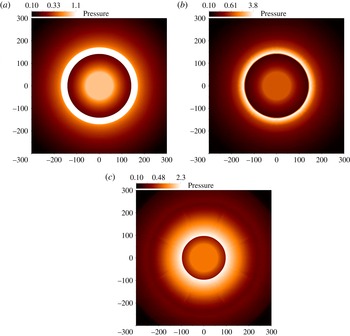
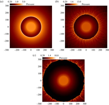
To understand the instability of the steady-state solutions computed previously for the standard Arrhenius law, we analyse two cases, shown in figure 4. In figure 8, we show the computed pressure profiles that correspond to the initial steady-state solution and two subsequent times,
 $t=10$
and
 $t=40$
. The initial radius of detonation is approximately 150. Over the short time,
 $t=40$
, the radius decreases to approximately 100. A careful look at the figures reveals that, in fact, the wave undergoes two-dimensional instability and detonation cells appear. However, the cells are very weak and do not visibly change the circular shape of the shock. The shock pressure during the collapse increases from approximately 1.1 at
 $t=0$
to 2.3 at
 $t=40$
. The dynamics remain essentially radially symmetric as, apparently, the two-dimensional instability has no time to develop and may additionally be suppressed by the increasing strength of the converging shock.
Collapse of the detonation that begins as the square-wave-like steady-state solution shown in figure 4(a). Times of the snapshots in (a)–(c) are, respectively,
 $t=0$
, 10 and 40. The domain size is
 $600\times 600$
, and the number of grid points is
 $1280\times 1280$
corresponding to 64 points per half-reaction zone.

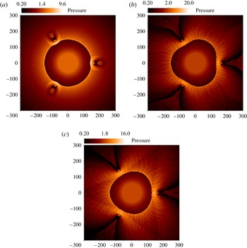
In contrast to the collapsing case considered above, figure 9 shows an expanding detonation. The initial condition is that of figure 4(b). The initial radius of detonation is nearly the same as in the collapsing case, but the detonation reaction-zone structure is very different, with a sharp decrease of pressure behind the lead shock and no visible induction zone. The two-dimensional instability in this particular case is rather strong and quickly results in the onset of a strong cellular detonation. The most important distinction of this case from the previous, collapsing, case is that the expansion is significantly slower. It takes approximately 400 time units for the detonation to expand to twice its initial radius. This slow expansion indicates that it may be possible to prevent the expansion by placing obstacles in the flow downstream of the shock to slow down the expanding flow of the reaction products.
Expansion of the detonation that starts as the non-square-wave-like steady-state solution shown in figure 4(b). Times of the snapshots in (a)–(c) are, respectively,
 $t=0$
, 150, 400. The domain size is
 $600\times 600$
; the number of grid points is
 $5120\times 5120$
, which corresponds to 20 points per half-reaction zone of the steady-state solution.

It must be pointed out that there are situations intermediate between the clearly collapsing detonation of figure 8 and the expanding detonation seen in figure 9. For the steady-state solutions having a structure in between that of a square wave and a regular profile, the detonation can be seen, in some cases, to start collapsing first, but a quick onset of cellular instability prevents the collapse and leads subsequently to an expansion. This observation indicates that the cellular instability may be playing a key role in preventing the collapse of the detonation wave, at least in the cases that we considered. Further theoretical study is required in order to determine whether this mechanism is universal.
4.2. Stabilization of detonation by obstacles
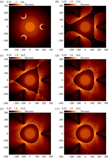
To see if the expanding detonation in the previous section can indeed be stabilized, we place several obstacles in the flow just downstream of the steady-state sonic locus. A multitude of possibilities arises depending on the number, size and shape of the obstacles. Importantly, however, very few obstacles are sufficient to prevent the expansion. The bow shocks that form ahead of the obstacle slow down the flow of products such that the detonation shock remains stabilized in the region between the source and the obstacles. The precise position and the shape of the resulting detonation wave depend on the choice of the obstacles and the details of the mixture and source conditions. In figure 10(a), we see the growth of small bow shocks around the obstacles, and the formation of a large triangle-shaped bow shock in figure 10(c) that stands downstream of the reaction zone and provides the necessary stabilizing support for the standing detonation. Numerical experiments with different numbers of obstacles equally spaced at the same radius show that using more than three obstacles in this particular case leads to a collapse of the wave. Whether one obtains a collapsing or stabilized solution is sensitively dependent on the multitude of parameters that play a role in the phenomenon. There appears to be no simple rule that allows one to a priori distinguish between the two cases.
Stabilization of the expanding detonation in figure 9 by three obstacles of radius 10. Times of the snapshots in (a)–(c) are, respectively,
 $t=10$
, 50, 700.

In both figures 9 and 10, the domain size is
 $600\times 600$
, and the number of grid points is
 $2560\times 2560$
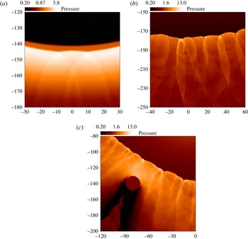
, which corresponds to 10 points per half-reaction zone of the steady-state solution. We carried out the same simulations with 20 point resolution and obtained essentially the same result, i.e. the dynamics and the global structure of the solution is the same, even though some minor details are slightly different. Close-up views of the detonation structure displayed in figures 8(b), 9(b) and 10(c) are shown in figure 12.
4.3. Initiation of detonation
Calculations described in the previous sections all take the steady-state solution as the initial condition for the two-dimensional simulations. This kind of calculation is a mostly academic exercise aimed at understanding the stability properties of a given steady-state solution. In practical situations, unstable steady states are hardly achievable, as detonations are always initiated by some source that leads, in the unstable case, to a pulsating or cellular detonation, without ever going to the steady-state solution. For this reason, an important question is how the standing detonation is initiated in the radial outflow. We can imagine many different means of doing so. Here, we investigate the possibility of the initiation of detonation from the non-reacting supersonic flow from the source after such a flow encounters rigid obstacles.
We place the same obstacles as in the previous section in the flow that is initially non-reacting and adiabatic. We observe that the bow shocks that form in front of the obstacles quickly initiate detonation waves stabilized by the obstacles (see figure 11 a). However, for some time, these detonation waves are separated from each other and form independent structures (see figure 11 b). Subsequently, these structures merge and reform (see figure 11 c–e) into the same final structure as we observed in figure 10.
Initiation of detonation by three obstacles of the same type and position as in figure 10. Images correspond to times (a)
 $t=10$
, (b)
 $t=50$
, (c)
 $t=100$
, (d)
 $t=200$
, (e)
 $t=500$
and ( f)
 $t=1500$
.

We have also computed the initiation starting with the initial condition corresponding to the collapsing solutions, figure 8. We find that the initiation results in an implosion.


4.4. Two-dimensional structures with the density-dependent rate function
As seen in § 3.2, the structure of the steady-state solutions for the modified Arrhenius model remains qualitatively the same as for the standard Arrhenius rate function. However, the corresponding two-dimensional dynamics is somewhat different. In particular, we find that both initial conditions shown in figure 7 lead to expanding solutions. The solution that starts with the square-wave-like initial condition is seen to have the shock position essentially unchanged for approximately 20 units of time, while its reaction zone starts expanding immediately. After approximately
 $t=20$
, with the heat-release region essentially detached from the lead shock, the shock starts expanding as well. Eventually, the detonation is seen to fail. We did not succeed in stabilizing this detonation with a ring of ten, nine or eight obstacles; in all these cases the detonation imploded. With seven obstacles, we obtain a detonation with a very irregular front structure that at some instant penetrates through the space between the obstacles and subsequently also fails.
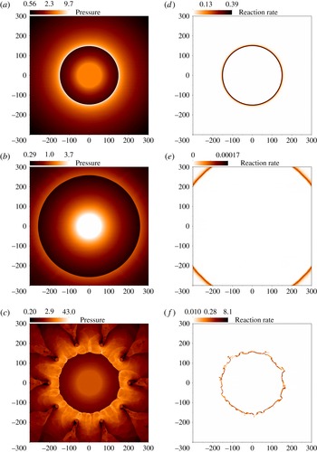
The simulation results for the detonation with a thin induction zone are displayed in figure 13. Figures 13(a) and 13(b) show the pressure field at times 0 and 35, respectively and figures 13(d) and 13(e) show the corresponding reaction-rate profiles. As we see, the detonation expands, but the expansion occurs almost without cell formation. In contrast to the standard Arrhenius rate function, in this case, the detonation fails with a marked detachment of the heat-release region from the shock, as shown in figure 13(e). If we place obstacles in the flow, this expanding detonation can be stabilized as shown in figure 13(c, f).
(a,b,d,e) The two-dimensional dynamics of the solution starting with the steady-state structure shown in figure 7(b); snapshots are taken at times 0 in (a,d) and 35 in (b,e). (c,f) The structure of the solution dynamically stabilized by the obstacles at time 2000. The domain size in all cases is
 $600\times 600$
and the number of grid points used is
 $2048\times 2048$
corresponding to 20 points per half-reaction zone of the steady-state solution. The obstacles have a radius 10 and are placed at distance 200 from the centre.

Finally, we note that for the two-dimensional simulations here we have slightly modified the numerical algorithm by mixing the high-order interpolation with a low-order interpolation for the fluxes to ensure positivity preservation at the points where pressure or density drop below certain small cut-off values (Hu, Adams & Shu Reference Hu, Adams and Shu2012). Typically, this mixing of fluxes is necessary near the lead shock for slowly moving shock waves in high-order methods such as WENO5.
5. Conclusions
In this work, by using compressible reactive Euler equations for a perfect gas reacting according to the single-step Arrhenius reaction model in its standard form or with a density dependence, we establish the existence of a steady-state detonation that stands in a supersonic flow radially emanating from a central source. The role of the inflow conditions, such as the stagnation enthalpy of the mixture and the inflow Mach number, in the existence and structure of the steady-state detonation solution is investigated. We show that, depending on the parameters, either there is no solution or there exist one or two solutions of the steady-state problem. In the case of the co-existence of two steady-state solutions, one of them can correspond to a relatively small detonation radius and the other to a large radius.
To investigate the stability of the steady-state solutions, we calculate the dynamics of the detonation by numerically integrating the two-dimensional reactive Euler equations. As initial conditions, we consider two distinct steady-state profiles, one of a square-wave type and the other having no clear induction zone. We find that the detonation either implodes quickly on the time scale of tens of steady half-reaction times, or expands slowly on the scale of hundreds of the same time units. The thin-reaction-zone solution in the standard Arrhenius model leads to a very slowly expanding detonation, in which cellular structures quickly form before any significant expansion takes place. These expanding detonations are shown to be stabilized by placing small rigid obstacles downstream of the steady-state detonation radius, such that a stable cellular detonation is established at some distance from the centre of the source. A similar calculation for the density-dependent rate function shows that the detonation expansion occurs with a deflagration front gradually detaching from the lead shock. As with the standard Arrhenius case, this detonation can also be stabilized by obstacles.
We have also numerically investigated the problem of the initiation of detonation by obstacles by placing the obstacles initially in a non-reacting adiabatic flow of the gas. The bow shock that forms around the obstacle quickly turns into a detonation that begins to expand. With the same obstacles as in the calculation starting with the steady-state solution, the same final detonation structure is obtained in the initiation case.
Our analysis of the detonation instability in the radial source flow is purely numerical, with the exception of the semi-qualitative arguments in § 4. It deals with the nonlinear cellular structures that arise as a result of the instability of the steady-state radially symmetric solution or by the initiation from a non-reactive source flow impinging on a series of obstacles. In order to understand the stability properties of the steady-state solutions in more detail, it is necessary to carry out linear stability analysis, which can afford a more complete parametric study than the one obtained with nonlinear simulations. Such an analysis can help elucidate and quantify the relative significance of purely radial instability, which appears to be generally present in our system, as opposed to the multi-dimensional instability.
A natural question is how the standing detonation explored in this work can be observed experimentally. As mentioned in the introduction, one can imagine such a detonation to form in a radial flow between two parallel plates such that a fuel–oxidizer mixture is supplied from a central source and achieves supersonic velocities upon passing through a ring-like de Laval nozzle. While our modelling points to the feasibility of such an experiment, a number of challenges have to be overcome in order to achieve this in practice. These include: (i) the difficulty of producing a supersonic flow of sufficiently high enthalpy required to create a strong standing detonation wave; (ii) the need to prevent pre-ignition by appropriate mixing in the supersonic flow ahead of the detonation shock; (iii) complications that can arise because of a significant temperature drop in the supersonic expansion of the gas if the gas emanates from the source at low temperatures. While recognizing such practical challenges, we hope the demonstration of the existence of a standing detonation in the novel, albeit idealized, configuration explored in this work provides an incentive for its further theoretical and experimental investigation.
In a sequel to this work, we explore the roles played by more complex heat-release laws and by the presence of frictional/heat losses in the existence and stability of the standing detonation in the radial flow.
Acknowledgements
Authors gratefully acknowledge financial support by King Abdullah University of Science and Technology (KAUST). We also thank B. Taylor of NRL for his generous permission to use and modify the solver for the reactive Euler equations that he has originally developed as part of Taylor et al. (Reference Taylor, Kasimov and Stewart2009). We also thank the referees for their critical remarks that helped us understand the multitude of issues with a practical realization of the system and we hope helped improve the presentation of our results.