I. INTRODUCTION
Many communication services, such as PCS, WiBro, WiMAX, and wireless LAN, have recently become available below 6 GHz and multiple frequencies have been allocated for the development of high-speed mobile communication systems. This has triggered research to design compact and multiband antennas [Reference Wong1]. In this context, microstrip and printed antennas are promising candidates for this design due to their low profile, low-weight, and ease of fabrication [Reference Balanis2].
On the other hand, various fractal geometries have found their way in antenna design to produce compact and multiband antennas benefiting from their unique space filling and self similarity. To provide bandwidth enhancement of the resonant bands, fractal-based slot structures are widely used in the design of multiband printed antennas. Conventional fractal geometries such as Koch, Cantor, Hilbert, Sierpinski, Minkowski, and other fractal curves have been successfully used to produce dual-band and multiband printed slot antennas for various wireless applications [Reference Sayem and Ali3–Reference Choukiker and Behera13].
It is worth to note that the applications of fractal geometries in the design of slot printed antennas can be classified into two categories. In the first, direct application of fractal geometries has been adopted [Reference Sayem and Ali3–Reference Bisht and Kumar10]. In such a case, the fractal geometries constitute the whole antenna slot structure. The multiband behavior of such antennas has been extracted almost directly without the need for any tuning elements or slot shape modification. However, in the second category, the slot structure is a combination of Euclidian structures, such as triangle, square, rectangle and other polygons, and fractal geometries superimposed on these structures, where each line segment is replaced by fractal curve with certain iteration level [Reference Krishna, Gopikrishna, Anandan, Mohanan and Vasudevan11–Reference Oraizi and Hedayati14]. In this case, the multiband behavior has been achieved using different approaches. These include the addition of tuning stubs to the feed line and modification of the slot structures by rotating it around the antenna axis.
In this paper, a compact printed fractal-based slot antenna is presented for use in dual-band wireless applications operating within the frequency range of 1–6 GHz. The slot structure of the proposed antenna is in the form of Cantor square fractal geometry of the second iteration. The antenna is fed with a 50 Ω microstrip line etched on the reverse side of the ground plane. The proposed antenna reveals a dual-band behavior with a wide separation between the upper and the lower resonant frequencies, making it suitable for most of the applications available in these bands. A parametric study carried out on the most effective elements of the antenna structure reveals that the proposed antenna offers more degrees of freedom to antenna designers.
II. THE ANTENNA STRUCTURE
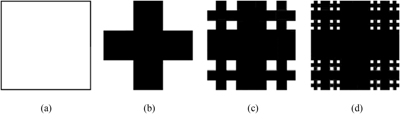
The Cantor square fractal is adopted to create the slot structure of the proposed printed antenna. The Cantor square fractal is a version of Cantor set made with squares instead of lines. Here, the generation process involves starting with a square, dividing it into nine squares, and cutting out all of them except for the corner ones. Figure 1 demonstrates the generation process of the Cantor square fractal structure up to the third iteration.
The steps of growth of the proposed Cantor square fractal up to the third iteration.

The fractal structure can be constructed using string rewriting beginning with a cell and iterating the rules [15]
 $$\left\{{0 \to \left[{\matrix{ 0 & 1 & 0 \cr 1 & 1 & 1 \cr 0 & 1 & 0 \cr } } \right]\comma \; \, \, 1 \to \left[{\matrix{ 1 & 1 & 1 \cr 1 & 1 & 1 \cr 1 & 1 & 1 \cr } } \right]} \right\}.$$
The size of the unit element after the nth iteration is
 $${L_n}={\left({\displaystyle{1 \over 3}} \right)^n}\comma \;$$
and the number of elements is given by the recurrence relation
 $${N_n}=4{N_{n - 1}}+5{\lpar 9\rpar ^n}\comma \;$$
where N 1 = 5, and the first few numbers of elements are 5, 65, 665, 6305, …[15]. Expanding out gives
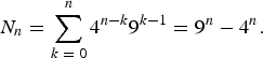 $${N_n}=\sum\limits_{k\;=\;0}^n {{4^{n - k}}} {9^{k - 1}}={9^n} - {4^n}.$$
The fractal dimension is therefore,
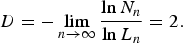 $$D=- \mathop {\lim }\limits_{n \to \infty } \displaystyle{{\ln {N_n}} \over {\ln {L_n}}}=2.$$
This means that the square is filled and the slot structure has no longer being with a fractal shape. It is then, expected that the antenna dual-band resonant response will diminish as the iteration level becomes higher.
III. THE ANTENNA DESIGN
Many microstrip-fed printed slot antennas with the slot structures corresponding to the Cantor square fractal geometries of the first, second, and third iterations depicted in Figs 1(a)–1(c), respectively, have been designed and their performance responses have been evaluated in the swept frequency range of 1–6 GHz. The slot structures of the modeled antennas are etched on the ground plane of an FR4 substrate with relative dielectric constant of ε r = 4.4 and height, h = 1.6 mm. For design convenience, the proposed antenna is fed by a 50 Ω microstrip feed line, printed on the reverse side of dielectric substrate. The microstrip line, with a width W f = 3.0 mm, is placed on the centerline beneath the rectangular slot (y axis) as demonstrated in Fig. 2. Numerical analysis of the antenna performance is carried out using the commercial Finite Integration Technique-based EM simulator, CST Microwave Studio (CST MWS) [16].
The proposed antenna layout with respect to the coordinate system; (a) top and (b) the side views.
Simulation results with a slot structure of the first iteration show that only one resonant band in this frequency range. This, of course, does not prevent the possibility of the existence of other resonant bands beyond this frequency range. Similarly, the slot structure of the third iteration makes the antenna resonating at one frequency band. However, the antenna with a slot structure of the second iteration has been found to offer an interesting dual-band resonance. This is expected from equation (5); as n approaches infinity the dimension of fractal slot is equal to 2 which means the slot is no longer being with a fractal structure. Consequently, effort is devoted to investigating the radiation characteristics offered by the antennas with slot structure based on the second iteration Cantor square fractal as depicted in Fig. 1(c).
A) Parametric study
The proposed printed fractal-based slot antenna depicted in Fig. 2 has been modeled, and its performance has been evaluated within the frequency range of 1–6 GHz using the prescribed substrate. Simulation results have shown that the antenna offers a dual-band response. The frequency ratio of the two resonant bands is of considerable importance in order to cover the different communication services below 6 GHz. In this context, simulation results reveal that the frequency ratio is influenced by two parameters; the feed line length and the aspect ratio of the antenna slot structure. A parametric study has been carried out to explore the effects of these two parameters on the antenna performance. Theoretical results are presented in the following two subsections.
1) THE EFFECT OF FEED LINE LENGTH
Figure 3 demonstrates the return loss responses of the dual-band slot antenna depicted in Fig. 2, with the feed line length varying from 21 to 27 mm. For the different feed line lengths, the antenna offers dual-band return loss responses with interesting features. As the feed line length is increased, the centers of the lower resonant bands are decreased due to increased coupling, while the relevant bandwidths are almost maintained constant about 0.75 GHz. On the other hand, the center of the upper resonant band is almost unchanged while the corresponding bandwidths decrease. However, below some value of the feed line length, the upper resonant band starts to diminish.
Simulated return loss responses of the antenna depicted in Fig. 2, with the feed line length as parameter.
2) THE EFFECT OF THE ANTENNA SLOT ASPECT RATIO
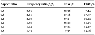
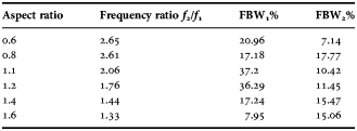
An interesting feature of the proposed antenna design is that it exhibits dual-band return loss responses with a considerable range of the resonant frequency ratio f 2/f 1 within the specified frequency range when varying the aspect ratio of the antenna slot structure. The aspect ratio of the fractal slot structure is defined as the ratio of slot width W s to its length L s. In this context, the parametric variable is the slot aspect ratio, which appears in Fig. 3 and Table 2, obtained by only varying the slot width W s while keeping its length L s constant. Figure 4 demonstrates the simulated return loss responses of the proposed antenna for selected values of the aspect ratio in the range of 0.75−1.5, in steps of 0.25. Table 2 provides the resonant fractional bandwidths for a wider range of aspect ratios than those depicted in Fig. 4. Figure 4 reveals that, on the contrary of the responses depicted in Fig. 3, that the rate of change of the lower resonant frequency is small as compared to that of the upper resonant frequency. When the aspect ratio becomes higher, the upper resonant frequency decreases considerably and approaches the lower band leading to lower frequency ratios. However, above some value of the aspect ratio, the two resonant bands are coupled together to form a single broadband resonance. On the other hand, as the aspect ratio becomes lower, the upper resonant band shifts further from the lower band leading to a higher frequency ratio.
Simulated return loss responses of the proposed antenna with the slot aspect ratios W s/L s as a parameter and a feed line length of 23 mm.
However, below some value of the aspect ratio, the lower resonant band starts to diminish. It is clear from the results depicted in Figs 3 and 4, and Table 1 that with appropriate dimensional scaling, the proposed antenna offers a dual-band behavior covering most of the available wireless services operating at 2.45 and 5.8 GHz.
The resulting frequency ratio versus the aspect ratio and the related fractional resonant bandwidths of the proposed antenna.
Finally, Fig. 5 demonstrates the current distribution on the surfaces of the antenna with aspect ratios corresponding to those modeled in Fig. 3 at the centers of the upper resonant bands. It is clear that as the aspect ratio is made lower, the corresponding slot structure becomes narrower; this in turns leads to a shorter effective radiating path. For this, the resonant band associated with this shorter path length becomes higher.
Simulated current distributions on the surface of the modeled antenna at the centers of the upper resonant bands for different value of antenna slot ratio.
In summary, the parametric study can be concluded as; the presented antenna possesses two propagated modes; the lower resonant mode is approximately determined by the overall slot size while the upper resonant mode is determined by the first slot size as seen from the microstrip feed line. In addition, the longer feeding line results in larger current distribution path in the upper zone around the slot and therefore leading to decrease the lower resonant frequency.
IV. NUMERICAL AND EXPERIMENTAL RESULTS
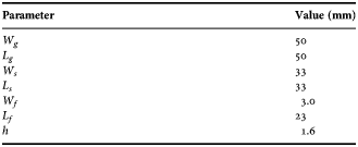
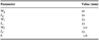
Several printed fractal-based slot antennas with slot structures as depicted in Figs 1(b)–1(d) have been initially designed with the layout as shown in Fig. 2. By appropriate dimensional scaling, the two resonant bands have to be found within the frequency range of 1–6 GHz. The resulting antenna has been found to have a square ground plane with a side length, L g = W g, of 50 mm, while the square containing the slot fractal structure has a side length, L s = W s, of 33 mm. The 50 Ω microstrip feed line, on the other side of the substrate, has a width, W f, of about 3.0 mm and length, L f, of 23 mm. As will be shown in the subsequent sections, a parametric study has to be carried out to explore the effects of the feed line length and the slot aspect ratio on the antenna performance.
The configuration of Fig. 2 has been fabricated. Figure 6 shows photographs of the fabricated prototype of this antenna. Table 2 summarizes the dimensions of the fabricated antenna. Measured and simulated return loss responses of the fabricated antenna prototype are depicted in Fig. 7. As it is implied from Fig. 7, the center of the measured lower resonant band is slightly right shifted away from the simulated one, while the simulated bandwidth is slightly narrower. On the other hand, the measured and simulated upper resonant bands are approximately co-centered and the corresponding bandwidths are almost equal. In summary, the simulated and measured results are in reasonable agreement.
Photograph of the fabricated prototype of the proposed antenna; (a) the top view and (b) the bottom view.
Measured and simulated return loss responses of the fractal based printed slot antenna depicted in Fig. 6 with feed line length of 23 mm.
Summary of the dimensions of the fabricated antenna.
The measured 10 dB return loss bandwidths for the lower and the upper resonant bands depicted in Fig. 7, are of about 42% (2.35–3.61 GHz) and 20% (5.15–6.25 GHz), respectively. This makes the proposed antenna suitable to cover many operating bands (2.4 GHz-Bluetooth, 2.4 GHz ISM, 2.4/5.8 GHz-WLAN, 3.5 GHz-WiMAX, 5.8 GHz-ITS).
As will be shown later, the four small isolated conducting squares contained in the antenna structure have a slight effect on its performance. However, examining the influence of the various parameters on the antenna performance, it has been found that the dominant factor in the antenna is the slot side length L s in terms of the guided wavelength λ g:
 $${\lambda _g}=\displaystyle{{{\lambda _ \circ }} \over {\sqrt {{\varepsilon _{eff}}} }} $$
where ε eff is the effective dielectric constant and is given by [Reference Pozar17]
 $${\varepsilon _{eff}}=\displaystyle{{{\varepsilon _r}+1} \over 2}+\displaystyle{{{\varepsilon _r} - 1} \over 2}\left({\displaystyle{1 \over {\sqrt {1+{{12h} / {{w_f}}}} }}} \right)\comma \;$$
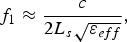
However, most of the currently available EM simulators provide direct calculation of ε eff in terms of the substrate specifications at the design frequency. In the other hand, only the first term of equation (7) has often used by many researchers [Reference Chen18]. In terms of the slot side length L s and the guided wavelength λ g, the lower resonant frequency, f 1, is given by:
 $${f_1} \approx \displaystyle{c \over {2{L_s}\sqrt {{\varepsilon _{eff}}} }}\comma \;$$
where c is the speed of light in free space, and λ g has been calculated in terms of the lower resonant frequency.
Figure 8 shows the measured and simulated electric field radiation patterns at XZ and YZ planes at 2.45 and 5.8 GHz. Again, the measured radiation patterns are in good agreement with those theoretically predicted. The results show almost monopole-like radiation patterns with almost omnidirectional pattern. The simulated three-dimensional (3D) far field radiation patterns of proposed antenna have been numerically calculated at 2.45 and 5.80 GHz, for a feed line length of 23 mm, as shown in Fig. 9.
Measured (red) and simulated (blue) far field radiation patterns of the proposed antenna in the YZ and XZ planes at (a) 2.45 GHz and (b) 5.80 GHz.
Simulated 3D far field radiation patterns of the proposed antenna at: (a) 2.45 GHz and (b) 5.80 GHz.
Figure 10 demonstrates the peak gain responses throughout the two resonant bands. The antenna offers a gain that varies in the range of 2.8–3.5 dB throughout the lower resonant band, and about 3.7–4.3 dB throughout the upper band. These values are sufficient for the operations of the most of the communication services operating within these frequency ranges.
Computed peak gains of the proposed antenna throughout: (a) the lower and (b) the upper resonant bands.
As compared with the related published works, the values of the corresponding gains throughout the two resonating bands are relatively high and approximately approach each other. However, this is not the case in most of the related work published in the literatures. In the majority of these works, the difference between the gain values corresponding to the two bands is considerably large with either the first band having the lower gain [Reference Kim and Hwang6, Reference Choukiker, Rai and Behera9, Reference Dhar, Maity, Gupta, Poddar and Ghatak19–Reference Jeong, Hwang, Park, Kim and Kim22] and the second band with the higher gain, or vice versa [Reference Hongnara, Mahatthanajatuphat and Akkaraekthalin23, Reference Hongnara, Mahattanajatuphat, Akkaraekthalin and Krairiksh24]. Equal gains of the corresponding bands but lower than those realized in this work have also been reported in [Reference Mahatthanajatuphat, Akkaraekthalin, Saleekaw and Krairiksh8, Reference Krishna, Gopikrishna, Anandan, Mohanan and Vasudevan11].
Furthermore, to provide more physical interpretation about the EM characteristics of the proposed antenna, the simulated surface current distributions at 2.50 and 5.80 GHz, are shown in Fig. 11. It is worth to note that there is a slight difference in the color bar scale for the simulated current distributions at the two frequencies. As the results of Fig. 11 (a) imply, the resonance at 2.5 GHz is attributed to the larger surface current path as compared with that at 5.8 GHz. However, at both resonant frequencies, the small isolated conducting square substructures have almost no current flowing on their surfaces. Therefore, it can be said that the lower resonant frequency has been predominantly determined by the slot structure perimeter as suggested earlier in the calculation of equation (8).
Simulated current distributions on the surface of the modeled antenna at: (a) 2.50 GHz and (b) 5.80 GHz.
V. CONCLUSION
A Cantor square fractal-based printed slot antenna is introduced for use in dual-band wireless applications operating at 2.45 and 5.8 GHz. Simulation results of several antenna models have shown that the proposed antenna structure offers interesting features in the that it can be a suitable candidate covering most of the recently available communication services operating at the resonant frequency bands. The antenna offers dual-band behavior with enhanced bandwidths and omnidirectional radiation patterns. A parametric reveals that the lower resonant mode is approximately determined by the overall slot size whereas the upper resonant mode is determined by the first slot size as seen from the microstrip feed line. Furthermore, the longer feeding line results in a larger current distribution path in the upper zone around the slot; leading to decrease the lower resonant frequency. Measured and computed return loss responses of the fabricated prototype have been found in good agreement. Measured 10 dB return loss bandwidths for the lower and the upper resonant bands are of about 42% (2.35–3.61 GHz) and 20% (5.15–6.25 GHz), respectively. This makes the proposed antenna suitable to cover many operating bands of the wireless communication systems (2.4 GHz-Bluetooth, 2.4 GHz ISM, 2.4/5.8 GHz-WLAN, 3.5 GHz-WiMAX, and 5.8 GHz-ITS). It is hopeful that the high degree of freedom offered by the proposed antenna design will make it an attractive choice of the antenna designer.
ACKNOWLEDGEMENTS
The authors would like to express their thanks to Dr. Sead Abushmelah form Systems Engineering Department, University of Arkansas at Little Rock, Little Rock, AR, USA, for his support in performing the required measurements. The authors would also like to extend their thanks to the staff of the Electronics Design Center, especially to Ghaleb N. Radad and Mahmood R. Muhsen from Ministry of Science and Technology, Iraq, for their support in the production of the preliminary antenna prototypes. Finally, the authors are grateful for the precise suggestions of the respected reviewers.
 Jawad Ali was born in Baghdad, Iraq in November of 1956. He received his B.Sc. and M.Sc. degrees in 1979 and 1986, respectively, from Al-Rasheed College for Science and Technology, Iraq. From 1989 to 1991, he joined Ph.D. study program at the Faculty of Engineering, Antonin Zapotocky Academy, (VAAZ), Brno, former Czechoslovakia. Since 2010, he has been a Professor of Microwave Engineering at the University of Technology, Iraq. Currently, he is the Deputy Dean for postgraduate studies and scientific affairs at the Department of Electrical Engineering. His fields of interests are microwave antenna miniaturization and design, passive microwave circuits design, and FPGA-based system design. He has more than 90 published papers in local and international conferences and peer-reviewed journals. Prof. Ali is a Senior Member of IEEE and a Member of IET.
Seevan Abdulkareem received her B.Sc. degree in Electronics and Communications from the University of Baghdad, Iraq in 2007 and M.Sc. degree in Microwave Engineering from the Department of Electrical Engineering, University of Technology, Iraq in 2013. From 2008–2011, she was a Lab Assistant at Al-Mansur University College. Her fields of interests are microwave antenna miniaturization, and design.
Ali Hammoodi has received his B.Sc. degree in Communication Engineering in 2011 from the Department of Electrical Engineering, University of Technology, Iraq. After graduation, he becomes an Engineer in the Microwave Engineering Laboratory at the Department of Electrical Engineering. Currently, he is working toward pursuing his M.Sc. degree from Systems Engineering Department, University of Arkansas at Little Rock, Little Rock, AR, USA. He has published many papers in international conferences and journals in the field of antenna design.
 Ali Salim was born in Baghdad, Iraq in 1975; he received his B. Sc. degree in Electrical Engineering and M. Sc. degree in Communication Engineering in 1999 and 2002 both from University of Baghdad, Iraq, respectively, and Ph.D. in Communication Engineering from the University of Technology, Iraq in 2011. He has published many papers in international conferences and journals in the field of microwave antenna design.
 Mahmood Yassen was born in Basrah, Iraq, in 1978. He received his B.Sc. degree in Communication Engineering from Al-Rasheed College of Science and Technology, Baghdad, in 2002 and M.Sc. degree in Communication Engineering from the University of Technology, Iraq, in 2013. Currently, he is working in the Communication Branch, Department of Electrical Engineering, University of Technology, Iraq, as an Assistant Lecturer. His fields of interests are microwave antenna and fractal antennas.
 Mohammed Hussan has received his B.Sc. degree in Electrical Engineering in Communication engineering from Al-Rasheed College of Science and Technology, Baghdad, in 1996 and M.Sc. degree in Communication Engineering from the University of Technology, Iraq, in 2013. Currently, he is working in the Communication Branch, Department of Electrical Engineering, University of Technology, Iraq, as an Assistant Lecturer. His fields of interests are microwave antennas and fractal antennas.
Hussain Al-Rizzo received his B.Sc. in Electronics and Communications (1979), Postgraduate Diploma in Electronics and Communications (1981), and M.Sc. in Microwave Communication Systems (1983) from the University of Mosul, Mosul. In 1987, he joined the Radiating Systems Research Laboratory, Electrical, and Computer Engineering Department, University of New Brunswick, Fredericton, NB, Canada where he obtained his Ph.D. (1992) in Computational Electromagnetics, Wireless Communications, and the Global Positioning System. He is currently a Professor of Systems Engineering at the University Arkansas at Little Rock. Before, he served as an Honorary Research Associate at the University of New Brunswick, and Senior Research Engineer at EMR Microwave Technology Corporation, Fredericton, NB, Canada. He has published over 35 journal papers, 70 conference presentations, and 2 patents. His research areas include implantable and wearable antennas and associated wireless systems, carbon nanotube-based antennas, design, modeling and testing of high-power microwave applicators, design and analysis of microstrip, and smart antennas for mobile radio systems.