NOMENCLATURE
- A 0
geometric projection area of air inlet
- A/F st
air-fuel ratio
- C d
drag coefficient
- C l
lift coefficient
- D
drag
- F
thrust
- g
gravitational acceleration
- g0
gravitational acceleration at ground level
- h
altitude
- I sp
specific impulse
- I spυ2
vacuum specific impulse
- k
air adiabatic index
- k 2
speed loss coefficient of the second stage liquid rocket
- L
lift
- m
mass of spacecraft
- ṁ
propellant mass flow rate
- ṁ air
the amount of air mass flow into the inlet
- m pl
payload
- Ma
Mach number
- N 2
a defined mass coefficient of the second stage liquid rocket
- p *
stagnation pressure of incoming flow
- T υac_2
engine vacuum thrust of the second stage rocket
- Q
dynamic pressure
- q (λ 0)
pneumatic function
- RBCC
Rocket-Based Combined Cycle Engine
- R T/W_2
thrust weight ratio of the second stage liquid rocket
- SERJ
Supercharged Ejector Ramjet
- S r
spacecraft reference area
- T stag
stagnation temperature of incoming flow
- υ orb
payload injection speed
- Δυ
velocity change
- V
Speed
- x
horizontal position
- α
angle-of-attack
- φ
flow coefficient of inlet
- η
inert mass fraction of the first stage RBCC spacecraft
- λ 0
speed coefficient of incoming flow
- μ k2
effective propellant mass ratio of the engine of the second stage liquid rocket at the shut-down point
- θ
trajectory inclination angle
- ϑ
pitch angle
- ρ
air density
- ω k
Gauss weights
- Φ
equivalent ratio
1.0 INTRODUCTION
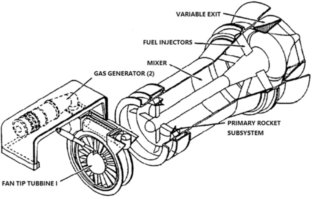
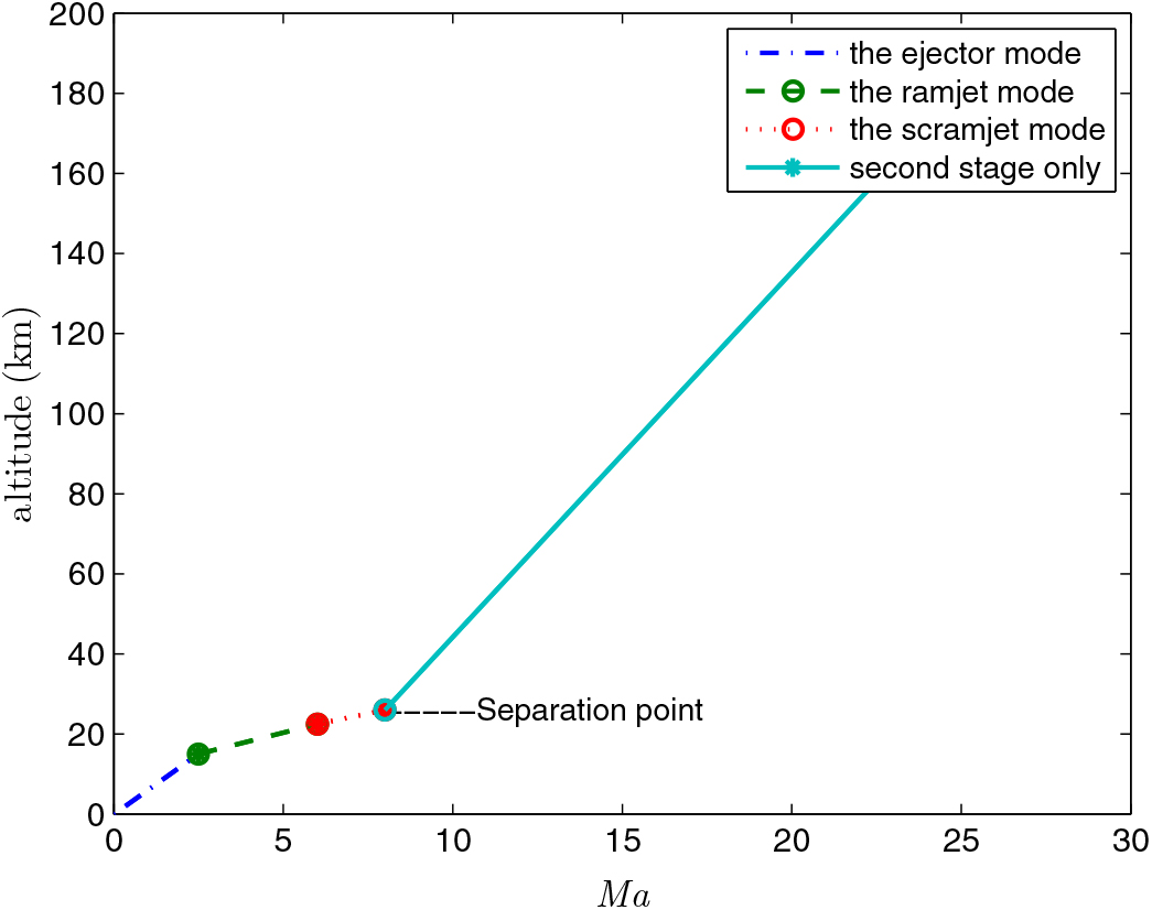
The rocket engine has a good acceleration characteristic and a large thrust-to-weight ratio. Because it doesn’t take advantage of the oxygen in the atmosphere, the specific impulse is lower. Therefore, it is not an ideal flight dynamic system within the atmosphere. The air-breathing engine utilizes the oxygen in the atmosphere, which greatly enhances the engine specific impulse. Because of its low thrust-to-weight ratio, it cannot take off by itself. Therefore, it cannot undertake the task of high-speed propulsion either. Rocket-Based Combined Cycle Engine (RBCC), which utilizes liquid propellant, represents a synergistic combination of traditional rocket engine and air-breathing engine within an integrated propulsion system. It gives full play to the advantages and characteristics of the above two propulsion modes and can work in an optimal way at different Mach numbers and altitudes. This method has the characteristics of multimodal integration structure design and realizes the best combination of economy and efficiency. It can take off on the ground and accelerates itself into orbit. It is one of the most ideal propulsion systems for hypersonic flight. Of course, there are many important aspects that affect its effectiveness, such as the mechanism of ejectors, the fuel injection strategies, thermal regulations and performances optimization technology in each mode, the smooth transition among working modes, the integration of structural optimization and so on. Similar to ramjet and scramjet aspirated engines, RBCC comprises of an inlet, a diffuser, a combustor and nozzles to process incoming air, add fuel, and expand the products combustion to generate thrust. The rocket is lighter and can provide thrust in a vacuum environment(Reference Fujikawa, Tsuchiya and Tomioka1–Reference Chae, Kim, Yee, Oh and Choi3). RBCC is typified by Marquardt’s Mach 8 Supercharged Ejector Ramjet (SERJ) as shown in Fig. 1(Reference Olds and Mccormick4) and works mainly in three modes: ejector mode, ramjet mode and scramjet mode(Reference Etele, Hasegawa and Ueda5–Reference Chojnacki and Clark9). The ejector mode ends, and the ramjet mode starts when the Mach number reaches 2.5. The ramjet mode ends, and the scramjet mode starts when Mach number reaches 6.
SERJ RBCC engine schematic(Reference Olds and Mccormick4).

A spacecraft with a RBCC propulsion system has obvious differences with a traditional spacecraft on the outline structure. This leads to the problem that it cannot adopt the traditional multistage rocket launch mass estimation method(Reference Pimentel10) when estimating RBCC spacecraft takeoff-mass. Ruan and Lv(Reference Ruan and Lv6) proposed a method to optimize the first stage takeoff-mass by using an augmented Lagrangian genetic algorithm, while the second stage takeoff-mass is calculated by using the conventional method. The method only needs the inert mass fraction (refer to Sections 2.2 and 4.5). However, the Genetic Algorithm has too many parameters. Once the mass estimation of the second liquid rocket did not meet the inert mass fraction constraint of the first-stage, the takeoff-mass must be calculated again until it satisfies the requirement. This may lead to a large amount of calculation and may be difficult to guarantee the iteration convergence. Lu(Reference Lu, He and Liu7) proposed an ascent trajectory design method for a RBCC-powered vehicle and gave the Mach number-dynamic pressure reference curve method. Still, there were similar problems. In Ref. 8, a quality estimation method is proposed for the horizontal two-stage-to-orbit spacecraft in combination with the difference of thrust/air-resistance characteristics in different flight phases and the change of a different engine mode specific impulse. However, this method requires a given separation point, which leads to the failure of the optimization of the Mach number and the takeoff-mass estimation, and the average speed of the two nodes is used when calculating the gravity loss. The error is larger.
In the past 10 years, Gauss pseudo-spectral method (GPM) has become a powerful tool in solving nonlinear optimal control problems(Reference Zhang, Gao, Chen, Sun and Zhang11–Reference Davies, Gubbins and Jimack14). In 2007, Huntington improved this method and showed that GPM has a higher precision and faster convergence speed in comparison with other algorithms in solving the optimal control problems(Reference Huntington15). These characteristics make GPM widely applicable in nonlinear optimal control problem with constraints.
Based on the idea of Ref. 6, this paper will simultaneously solve the problem of takeoff-mass and trajectory optimization of two-stage-to-orbit RBCC-RKT spacecraft. However, the solution is considered as a nonlinear optimal control problem. The takeoff-mass range of the second stage liquid rocket is considered as a constraint condition, which can improve the convergence of the algorithm. Then the problem can be solved by using Gauss pseudo-spectral method (GPM) with relatively fewer parameters.
In view of multiple data forms and piecewise functions and in order to tabulate data, an integrated interpolation approach is employed to avoid the convergent difficulty. Finally, the effectiveness of the algorithm is verified by numerical results.
The remaining parts of this paper are organized as follows. The problem is formulated in Section 2.0. Section 3.0 gives a brief introduction of GPM. The RBCC-RKT global optimization process under the framework of GPM is presented in Section 4.0. In Section 5.0, the simulation results are presented and analysed. The concluding remarks are summarized in Section 6.0.
2.0 MATHEMATICAL MODEL OF RBCC-RKT TWO-STAGE SPACECRAFT
This paper studies a two-stage spacecraft utilizing a liquid oxygen and liquid hydrogen (LOX/LH2) RBCC engine in the first stage and LOX/KEROSENE liquid rocket engine (RKT) in the second stage(Reference Meyer, Chato, Plachta, Zimmerli, Barsi, Van Dresar and Moder16). When the specified Mach number and altitude are reached, the booster of the first stage falls, and the second stage starts. The schematic of the two-stage spacecraft is shown in Fig. 2.
The two-stage spacecraft schematic.
2.1 Model of the first stage of the spacecraft
In estimating the takeoff-mass of the two-stage spacecraft, the following simplified dynamic model in the vertical plane is used(Reference Ruan and Lv6).
 \begin{equation}
\begin{cases} {\frac{dV}{dt} =\frac{F\cos \alpha\,-\,D\,-\,mg\sin \theta }{m} }\\[10pt]
{\frac{d\theta }{dt} =\frac{F\sin \alpha\,+\, L\,-\,mg\cos \theta }{mv} }\\[10pt]
{\frac{dx}{dt} =V\cos \theta } \\[10pt]
{\frac{dh}{dt} =V\sin \theta } \\[10pt]
{\frac{dm}{dt} =-\dot{m}}\\[10pt]
{u_{1} =\dot{m}}\\
{u_{2} =\alpha =\vartheta -\theta } \end{cases}\label{eq1}
\end{equation}
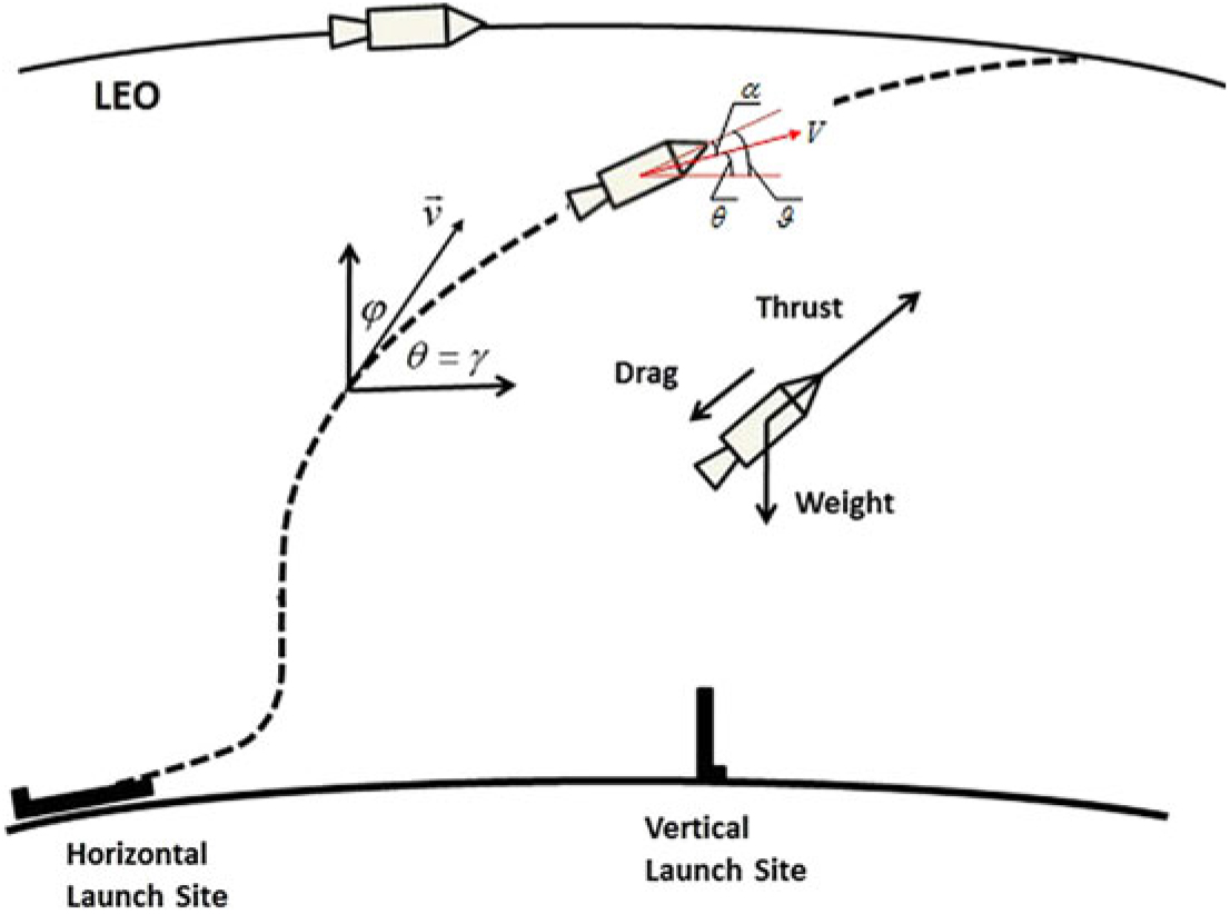
where u 1 and u 2 are two control variables. The illustration of the flight trajectory and critical mission altitudes is depicted in Fig. 3(Reference Daidzic17).
Spaceplane GT (α = ϑ–θ) trajectory when launched nearly horizontally. Not to scale.

The thrust and aerodynamic forces are as follows:
 $${\rm{ }}\left\{ {\begin{array}{*{20}{c}}
{F = \dot m{I_{sp}}{g_0}} \\
{D = {C_d}Q{S_r}} \\
{L = {C_l}Q{S_r}} \\
\end{array}} \right.$$
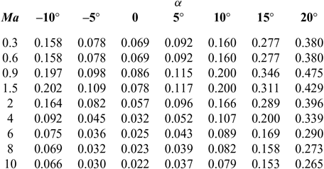
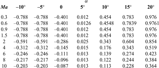
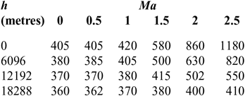
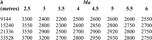
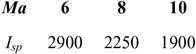
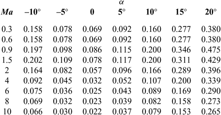
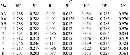
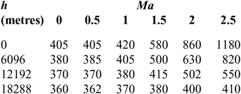
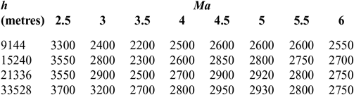
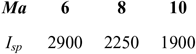
C d and C l are shown in Tables 1 and 2(Reference Brock and Captain18); I sp is shown in Tables 3–5(Reference Meyer, Chato, Plachta, Zimmerli, Barsi, Van Dresar and Moder16) under ejector mode, ramjet mode and scramjet mode, respectively. Tables 3 and 4 are obtained from Ref. 19 and Table 5 from Ref. 20. The aerodynamic raw data of the first-stage aircraft is obtained from the X–43A(Reference Brock and Captain18). The aerodynamic raw data of the second-stage aero-vehicle is computed by using the Missile DATCOM(Reference Ruan, He and Lv21) software. Q = ρV 2/2 is the dynamic pressure and is assumed that Q Q ≤ Q max under the ejector mode, Q = Q maxunder the ramjet and scramjet mode, (where Q max is the maximum value of dynamic pressure Q); ρ is calculated as follows:
 $$\left\{ {\begin{array}{*{20}{c}}
{\rho = 1.225{{\left( {1 - 0.000022557h} \right)}^{4.255886}},\quad \quad h \le 11000} \hfill \\
{\rho = 0.36391{e^{ - 0.000157688\left( {h - 11000} \right)}},\quad \quad 11000 \lt h \le 20000} \hfill \\
{\rho = 0.088035\left( {1 + \frac{{0.001\left( {h - 20000} \right)}}{{216.65}}} \right),\quad \quad h > 20000} \hfill \\
\end{array}} \right.$$
Drag coefficient C d
Lift coefficient C l
I sp of ejector mode
I sp of ramjet mode
I sp of scramjet mode
2.2 Calculation of thrust
The takeoff-mass m 0 of the two-stage-to-orbit spacecraft includes the first stage of launch vehicle mass m 01, and the second-stage RKT rocket mass m 02 includes the payload. m 01 includes the fuel mass, m 01p, and the fuselage structure mass, m 01s(Reference Etele, Hasegawa and Ueda5), namely,
 \begin{equation}
m_{0} =m_{01} +m_{02} =\left(m_{01p} +m_{01s} \right)+m_{02}\end{equation}
Thus, we can get the inert mass fraction η of the first-stage RBCC spacecraft
 \begin{equation}
\eta =\frac{m_{01s} }{m_{01p} +m_{01s} }\end{equation}
The RBCC engine is the first-stage propulsion system, and the liquid rocket engine is the second propulsion system. There are two calculation condition assumptions(Reference Ruan, He and Lv21):
1. The liquid rocket can shut down or restart according to the requirement. The vacuum specific impulse I spυ2 is a constant value that does not vary with the flight state. The propellant mass flow rate ṁ is automatically adjusted within a certain range with the thrust requirements.
2. The RBCC engine works in three modes: the ejector mode (Ma = 0 ~ 2.5), the ramjet mode (Ma = 2.5 ~ 6) and the scramjet mode (Ma > 6.0). The mode conversion is instantaneous. The specific impulse of the RBCC engine is a function of Mach number and flight altitude, and its change law is known. The propellant mass flow can be adjusted. The regulation law and the engine working mode are different. The specific performance is as follows:
a) The ejector mode, assuming that the mass flow of the initial time is ṁ 0 mass flow in the ejector mode is the largest. Thus, the mass flow of this mode is a function of Mach number and altitude as(Reference Ruan and Lv6):
(6) \begin{equation}
\dot{m}=\dot{m}_{0} \beta \left(Ma,h\right)\end{equation}
where 0 ≤ β (Ma, h) ≤ 1, which is subject to the Mach number and altitude and represents the change of ṁ. It can be calculated according to the engine data in the ejector mode and the curve of specific impulse in the Ref. 22. According to the Ref. 21, its calculation method is: if the thrust and specific impulse are known, the engine propellant mass flow rate of a different flight speed and flight altitude can be obtained by the thrust equationF = ṁ I spg 0. If divided by the propellant mass flow rate of zero altitude and zero Mach, respectively, then we will get β.
b) The ramjet mode and the scramjet mode

In the ramjet mode and scramjet mode, the ejector rocket will be shut down. The propellant mass flow rate is determined by the amount of air mass flowing into the inlet and the Equivalence ratio Φ,
 $$\dot m = \frac{{\Phi \times {{\dot m}_{air}}}}{{\left( {A/{F_{st}}} \right)}}$$
where ṁ air can be calculated as follows:
 \begin{equation}
\dot{m}_{air} =k\frac{p^{*} }{T_{stag} } A_{0} q\left(\lambda _{0} \right)\varphi\end{equation}
Then, according to the thrust equation F = ṁ I spg 0, the engine thrust of the RBCC can be represented as:
 $$F = \left\{ {\begin{array}{*{20}{c}}
{{{\dot m}_0}\beta \left( {Ma,h} \right){I_{sp}},\quad \quad 0 \le Ma \le 2.5} \hfill \\
{\frac{\Phi }{{\left( {A/{F_{st}}} \right)}}k{\textstyle{{p*} \over {{T_{stag}}}}}{A_0}q\left( {{\lambda _0}} \right)\varphi {I_{sp}},\;2.5 \le Ma \le 10} \hfill \\
\end{array}} \right.$$
Under certain flight conditions, the engine specific impulse is known. The engine thrust is determined only by the propellant mass flow rate. In the ejector mode, thus, the thrust is determined by propellant mass flow ṁ 0 at zero time and zero altitude. But in the ramjet mode and scramjet mode, it is determined by the Equivalence ratio Φ, the geometric projection area of air inlet A 0 and the inlet flow coefficient φ. ṁ 0 is a given value, A 0 a constant value and φ a function of Mach number Ma.
2.3 Takeoff-mass constraints of the second-stage liquid rocket
The takeoff-mass of the second-stage liquid rocket can be estimated by the following method(Reference Ruan and Lv6):
 \begin{equation}
m_{02} =\frac{m_{pl} }{1-N_{2} -\left(1+k_{2} \right)\mu _{k2} }\end{equation}
and
 \begin{equation}
N_{2} =N_{2}^{0} +\frac{T_{vac\_ 2} }{R_{T/W\_ 2} m_{02} g_{0} }\end{equation}
 \begin{equation}
\mu _{k2} =1-e^{\frac{\left(1-k_{2} \right)I_{spv_{2} } }{\Delta v} }\end{equation}
Other coefficients are calculated by the following empirical equations(Reference Ruan and Lv6,Reference Ruan, He and Lv21) :
 \begin{equation}
\left\{\begin{array}{l} {N_{2}^{0} =0.01\left(1+5e^{-0.034m_{02} } \right)} \\ {T_{vac\_ 2} =m_{02} gT} \\ {\Delta v=v_{orb} -V\left(t_{f} \right)} \end{array}\right.\end{equation}
where
 \begin{equation}
g=g_{0} \left(\frac{6371000}{6371000+h} \right)^{2}\end{equation}
with g 0 = 9.80665m/s2.
If the thrust-to-weight ratio, the payload of the second-stage rocket, the separation speed and separation altitude are known, we can calculate the takeoff-mass of the second-stage rocket with any given initial value of m 02 through several iterations by using the above method.
3.0 A BRIEF INTRODUCTION TO GAUSS PSEUDO-SPECTRAL METHOD (GPM)
3.1 Continuous optimal control problem
For the dynamic system:
 \begin{equation}
\dot{x}=f\left(x\left(t\right)\!,u\left(t\right)\!,t\right)\end{equation}
where x(t)∊R n and u(t)∊R m are state and control variables, respectively, and the function f:R n × R m × R → R n determine the control variables to optimize the following cost function:
 \begin{equation}
J=\Psi (x(t_{f}), t_{f} )+\int _{t_{0} }^{t_{f} }g\, (x(t), u(t), t) dt\end{equation}
and meet the boundary constraints
 \begin{equation}
\phi\, (x(t_{0} ), t_{0}, x(t_{f} ), t_{f} )=0\end{equation}
and the process constraints
 \begin{equation}
C\,(x(t), u(t), t_{0} ,t_{f} )\le 0\end{equation}
where ϕ : R n × R × R n × R → R q and C : R n → R r.
3.2 The basic principle of GPM
The essence of GPM is to replace the original infinite-dimension dynamic optimal control problem with a finite-dimension static nonlinear programming (NLP) by eliminating differential and integral equations. A brief review of pseudo-spectral method (PSM), especially GPM, is presented here. More details can be found in Ref. 12.
Firstly, the original time interval [t 0, t f] of the optimization problem is converted to the time interval [−1, 1] as
 \begin{equation}
\tau =\frac{2t}{t_{f} -t_{0} } -\frac{t_{f} +t_{0} }{t_{f} -t_{0} }\end{equation}
By using Equation (19), Equation (16) is reformulated in terms of τ as:
 \begin{equation}
J=\Psi (x(1), t_{f} )+\frac{t_{f} -t_{0} }{2} \int _{-1}^{1}g\,(x\,(\tau ), u\,(\tau ), \tau )\, d\tau\end{equation}
Similarly, the dynamic Equation (15) and the boundary constraints (17) are replaced by
 \begin{equation}
\frac{2}{t_{f} -t_{0} } \frac{dx}{d\tau } =f\left(x\left(\tau \right),u\left(\tau \right),\tau \right)\end{equation}
and
 \begin{equation}
\phi \left(x\left(-1\right),t_{0} ,x\left(1\right),t_{f} \right)=0\end{equation}
respectively.
In GPM, the Legendre-Gauss (LG) points τ k (1 ≤ k ≤ N − 1), distributed on the interval [-1, 1], are defined as the roots of
 \begin{equation}
P_{N} \left(\tau \right)=\frac{1}{2^{N} N!} \frac{d^{N} }{d\tau ^{N} } \left[\left(\tau ^{2} -1\right)^{N} \right]\end{equation}
while τ 0 = −1, τ N = 1.
The continuous state and control variables are approximated by the N th Lagrange interpolation polynomials in the form
 \begin{equation}
x\,(\tau )\approx X(\tau )=\sum _{i=0}^{N}L_{i} (\tau)\, X(\tau _{i} )\end{equation}
and
 \begin{equation}
u(\tau )\approx U(\tau )=\sum _{i=1}^{N}L_{i} (\tau)\, U(\tau _{i} )\end{equation}
where the Lagrange interpolation polynomial is
 \begin{equation}
L_{i} \left(\tau \right)=\prod _{j=0,\ j\ne i}^{N}\frac{\tau -\tau _{i} }{\tau _{i} -\tau _{j} }\end{equation}
Secondly, the dynamic Equation (15) is discretized at the node points, as in Ref. 15:
 \begin{equation}
\dot{x}\left(\tau \right)\approx \dot{X}\left(\tau \right)=\sum _{i=0}^{N}\dot{L}_{i} \left(\tau \right)X\left(\tau _{i} \right)
\end{equation}
where the differential matrix can be computed offline:
 \begin{equation}
D_{ki} =\dot{L}_{i} \left(\tau _{k} \right)=\left\{\begin{array}{l} {\dfrac{\left(1+\tau _{k} \right)\,\dot{\!P}_{K} \left(\tau _{k} \right)+P_{K} \left(\tau _{k} \right)}{(\tau _{k} -\tau _{i} )[(1+\tau _{i} )\,\,\dot{\!P}_{K} (\tau _{i} )+P_{K} (\tau _{i} )]} ,i\ne k} \\[12pt] {\dfrac{\left(1+\tau _{i} \right)\,\ddot{\!P}_{K} \left(\tau _{i} \right)+2\,\dot{\!P}_{K} \left(\tau _{i} \right)}{2[(1+\tau _{i} )\,\,\dot{\!P}_{K} (\tau _{i} )+P_{K} (\tau _{i})]},\quad i=k} \end{array}\right.\end{equation}
Thus, the dynamic differential equation constraints are transformed into the algebraic constraints:
 \begin{equation}
\sum _{i=0}^{K}D_{ki} X\, (\tau _{i}) -\frac{t_{f} -t_{0} }{2}\ f\,(X(\tau _{k} ), U(\tau _{k} ), \tau _{k} ;t_{0} ,t_{f} )=0,\quad k= 1,..., K\end{equation}
Meanwhile the terminal moment node is not included in the approximate expression of state variables. So, the terminal state should satisfy the constraint conditions of dynamic equation, namely,
 \begin{equation}
x(\tau _{f}) = x(\tau _{0} )+\int _{-1}^{1}f(x(\tau ),u(\tau ),\tau )d\tau\end{equation}
The differential of the terminal constraint and integral can be obtained by Gauss integral, namely,
 \begin{equation}
X(\tau _{f} )=X\left(\tau _{0} \right)+\frac{t_{f} -t_{0} }{2} \sum \omega _{k}\, f\, (X\, (\tau _{k} ), U\,(\tau _{k} ), \tau ;t_{0} ,t_{f} )\end{equation}
Thirdly, the continuous-time cost function (16) is approximated by Gauss integral, as follows:
 \begin{equation}
J=\Phi \left(X_{0} ,t_{0} ,X_{f} ,t_{f} \right)+\frac{t_{f} -t_{0} }{2} \sum _{k=1}^{N}\omega _{k} g\left(X_{k} ,U_{k} ,\tau _{k} ;t_{0} ,t_{f} \right)\end{equation}
Similarly, the terminal and process constraints can also be reformulated.
According to the mathematical transformation above, the optimization problem based on GPM can be described as seeking the status variables X i (i = 0, …, K), the control variables U k (k = 1, …, K) on discrete nodes and the ending time t f to minimize the cost function Equation (32). Meanwhile, X i and U k satisfy Equations (29), (31) and the following two equations:
boundary constraints
 \begin{equation}
\varphi \left(X_{0} ,t_{0} ,X_{f} ,t_{f} \right) = 0\end{equation}
and process constraints
 \begin{equation}
C\left(X_{k} ,U_{k} ,\tau _{k} ;t_{0} ,t_{f} \right)\le 0,\quad k = 1,\ldots ,K\end{equation}
From the procedures described in this section, the optimization problem is transformed into a general NLP, namely,
 \begin{equation}
\begin{array}{l} {min \quad F\left(y\right)\; \; \; y\in R^{M}} \\
{s.t.\quad g_{j} \left(y\right)\ge 0,\quad j = 1,2,\ldots ,p} \\
\quad\quad{h_{j} \left(y\right) = 0,\quad j = 1,2,\ldots ,l} \end{array}\end{equation}
where y is a designed variable that contains state variables, control variables and the end time.
There are many effective methods to solve NLP availability. Among them, sequential quadratic programming (SQP) is widely used because of its maturity(Reference Tawfiqur and Zhou23,Reference Ghorbani and Salarieh24) .
4.0 GLOBAL OPTIMIZATION PROCESS BY USING GPM
Here, the designed variables used in GPM include the state variables (speed V, elevation angle θ, position x and h of the spacecraft), the control variables (u 1, u 2) and the end time t f. Normally, numerical calculation is aimed at the limited range. Thus, the boundary conditions of the range cannot be arbitrarily given. It requires good, sufficient stability of the mathematical variables and has an obvious physical significance(Reference Singer and Pope25). The designed variables are sensitive to the constraints and the cost function. If there are some changes of the constraints and cost function, the optimization results of the variables will be different or incorrect.
4.1 Initial values
For the takeoff stage, the rocket must satisfy the initial value requirements, including elevation angle θ 0, angle-of-attack α 0, speed V 0, position (x 0, y 0) and mass search interval [m 0 min, m 0 max]. The optimization objective is to seek the optimal takeoff-mass within the search interval.
4.2 Process constraints
According to the performance specifications of the launch vehicle, the following process constraints should be considered:
 \begin{equation}
\Phi _{\min } \le \Phi \le \Phi _{\max }\end{equation}
 \begin{equation}
\theta _{\min } \le \theta \le \theta _{\max }\end{equation}
 \begin{equation}
Q-Q_{\max } \le 0\; \; \; {\rm the\; ejector\; mode}\end{equation}
 \begin{equation}
Q-Q_{\max } =0\; \; \; \; {\rm the\; ramjet\; and\; scramjet\; mode}\end{equation}
4.3 Terminal constraints
According to the separation constraint, several requirements of the algorithm should be satisfied with the requirements optimized in their constraint ranges. The following separation terminal constraint ranges are considered: the elevation angle range [θ f min, θ f max], the speed range [V f min, V f max], the position range [x f min, x f max] and [h f min, h f max] and the mass range [m f min, m f max]. Here, f is the terminal time point.
4.4 Control constraints
Here, we select the mass flow ṁ and the angle-of-attack α as the control variables and limit them to
 \begin{equation*}{\dot{m}\in \left[\dot{m}_{\min } ,\dot{m}_{\max } \right]}\ {\rm and}\ {\alpha \in \left[\alpha _{\min } ,\alpha _{\max } \right]}.\end{equation*}
4.5 Mass constraint of the second-stage RKT rocket
We investigate the optimal separation time of the RBCC-RKT launch vehicle, and the second RKT rocket is selected as a constraint, which can avoid the double-counting problem and simplify the algorithm (Because GPM is a global optimization algorithm, if the inert mass fraction is taken as a constraint, it can be calculated in the optimization process. If it is not taken as a constraint, it is necessary to find out whether the optimization result meets the inert mass fraction after optimization. If it is not satisfied, it needs to be optimized again, which results in the increase of optimization times.).
The inert mass fraction constraint is
 \begin{equation}
\frac{m_{01f} -m_{02} }{m_{01} -m_{02} } =\eta\end{equation}
4.6 Cost function
The objective of the optimization is to minimise the consumed propellant mass prior to separation(Reference Ruan, He and Lv21), but the GPM algorithm seeks the minimum. So, the cost function is then to minimize:
 \begin{equation}
J_{{1}} =\int _{t_{0} }^{t_{f} }\dot{m} dt\end{equation}
In addition, for the reuse of the rocket, we choose the trajectory inclination angle at separation θ f = 0 as the cost function as well, namely,
 \begin{equation}
J_{{2}} ={\rm abs}(\theta _{f} )\end{equation}
For the convenience of solving by GPM, the above three objective functions are summed weighted:
 \begin{equation}
J=f_{1} \cdot J_{1} +f_{2} \cdot J_{2}\end{equation}
where f 1, f 2 are weighting factors.
This multi-objective optimization problem (MOP) of takeoff-mass can be transformed into a general multi-objective parameter optimization problem by using GPM. The Karush-Kuhn-Tucker condition (KKT) of the NLP transformed by GPM is consistent with the first-order optimality condition of the discrete Hamilton boundary value problem under certain conditions(Reference Benson, Huntington, Thorvaldsen and RAO26). The optimal Pareto front of the multi-objective can be got by using the Normal Boundary Intersection method (NBI) to solve the MOP of GPM(Reference Lei, Jianquan, Tao, Zhiwei and Zhengnan27,Reference Logist, Houska, Diehl and Van Impe29) . For this, the GPM toolbox GPOPS that we used has the following modifications according to the Ref. 27:
1. The Mayer and Lagrange indexes in the cost function are output respectively for each function.
2. The sparse matrix template is modified.
3. The NBI method is added to the GPOPS.
4.7 Aerodynamic data processing
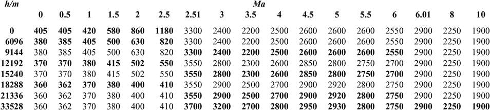
The data in Tables 3–5 of I sp is segmented, which will cause severe difficulties to the convergence of the optimization process. So, in order to facilitate the use of GPM algorithm, we adopt an integrated interpolation strategy for the data at different stages(Reference Chiu30,Reference Pini, Spinelli, Persico and Rebay31) .
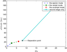
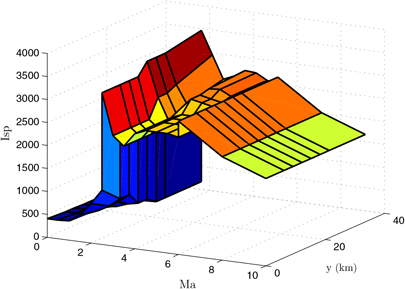
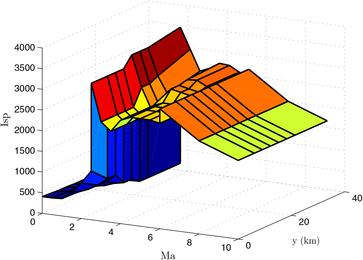
According to the data in Tables 3–5 in different phases, there is no overlap in the Mach dimension so that they can be merged in a straightforward way. To facilitate representation, this composite table is represented as Table I sp. A specific method is also proposed in the Appendix. Finally, we can obtain a unified rectangular data table, and the data of a two-dimensional curved surface is shown in Fig. 4. A consistent two-dimensional interpolation method can be used to speed-up the convergence of the optimization algorithm.
I sp data.
Air density is a piecewise function of altitude. To make convergence faster, they are also combined in a unified air density table, where the altitude sampling points are [0, 1000, …, 76000](m) with an interval of 1000 m.
4.8 The process to attain the optimized results
Set the number of iterations and the precision requirement, go to Step 1.
Step 1: Input the initial value, the precision tolerance and all constraints, where the number of input LG point N is usually a small value at the first time.
Step 2: Process the following optimization to obtain the optimal solution by using GPM:
min cost function (43)
s.t. equality constraints (10)
and inequality constraints (36)–(40)
Step 3: Solve the NLP with software SNOPT.
Step 4: If the iteration number is not reached, and the precision requirement is not met, then increase the number of nodes, N, and go to Step 1. Otherwise, end up with the optimal solution.
5.0 OPTIMIZATION RESULTS AND ANALYSIS
5.1 Simulation 1: Flight trajectory before the separation
For comparison convenience, we adopted some values of Ref. 6 and assumed that a two-stage spacecraft takes off horizontally, and the takeoff altitude h = 0km. When the spacecraft takes off from the ground, the elevation angle θ = 0o, the angle-of-attack α = 7o, the payload m pl = 500kg and the Mach number Ma = 0.4. Additionally, Q max = 105348 Pa, the speed loss coefficient of the second-stage rocket k 2 = 0.15, the payload injection speed v orb = 7749m/s and the thrust-to-weight ratio of the second-stage rocket T = 1.2. Then, take η = 0.568, the reference area S r = 36.144ft 2, the vacuum specific impulse of the second-stage liquid rocket I spv 2 = 390s, N = 20, precision tolerance = 1e-3. Since the optimal takeoff quality is as important as the successful recovery of the rocket, f 1 = f 2 = 0.5 is used to achieve both purposes.
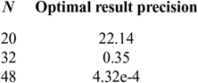
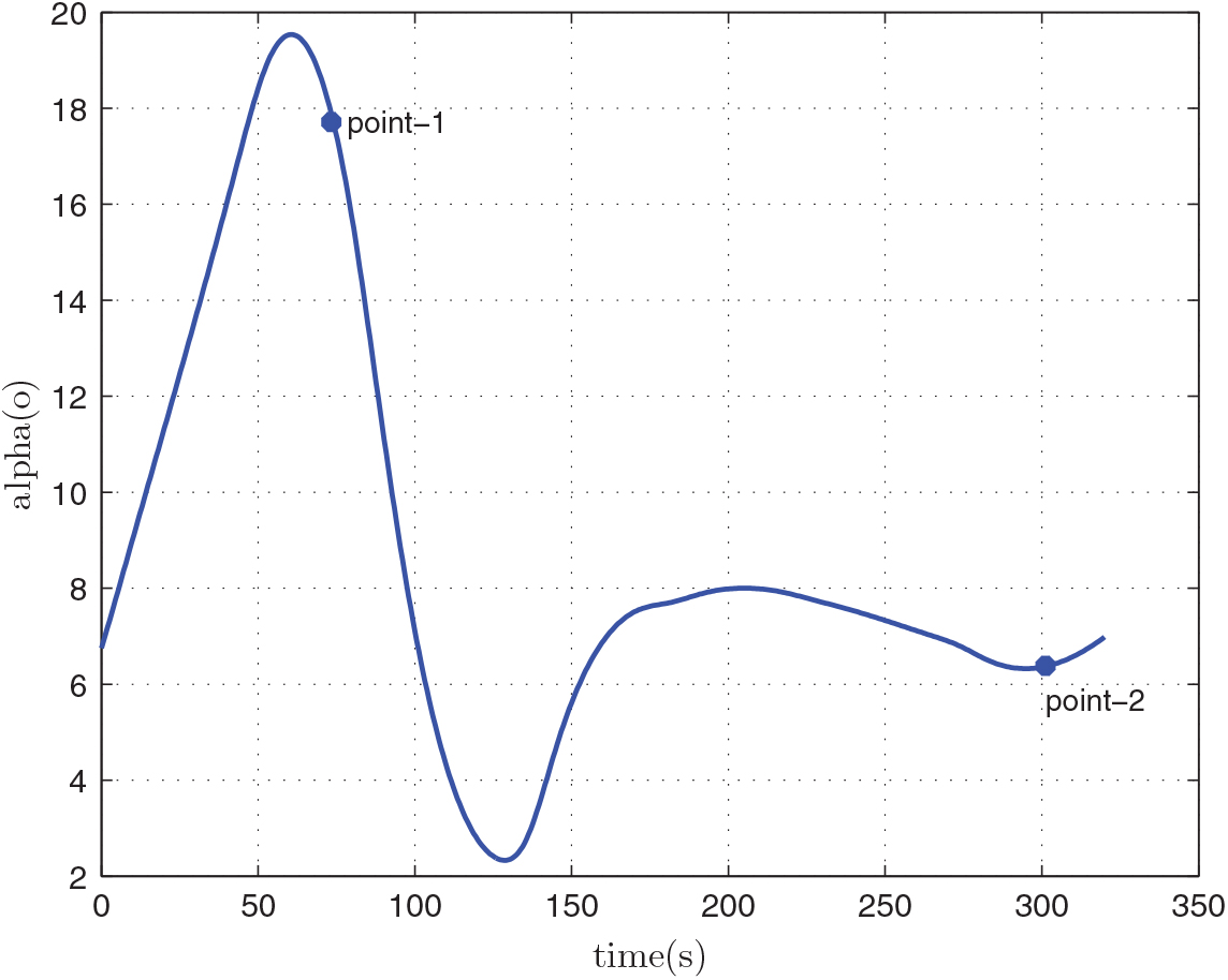
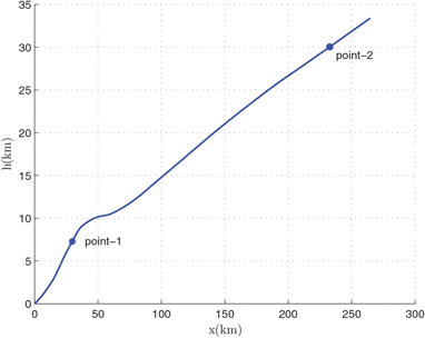
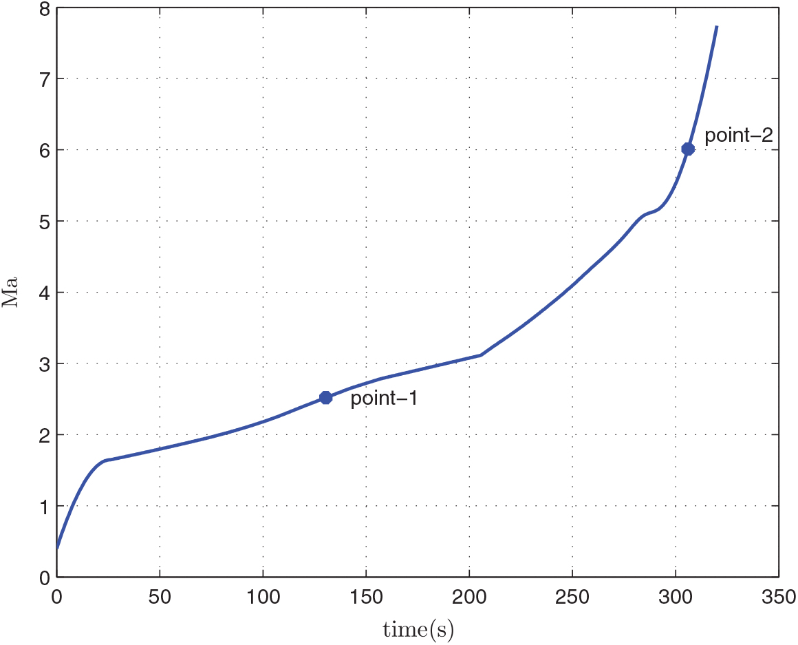
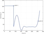
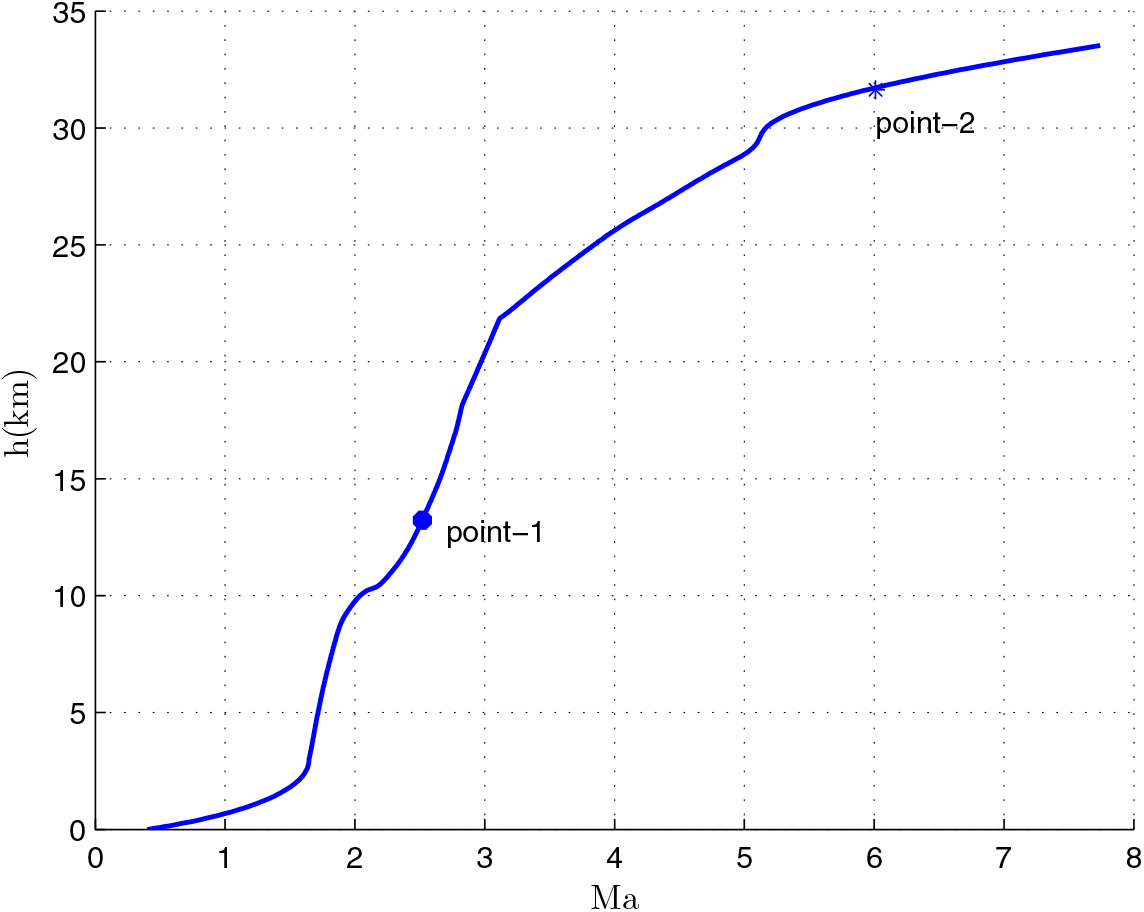
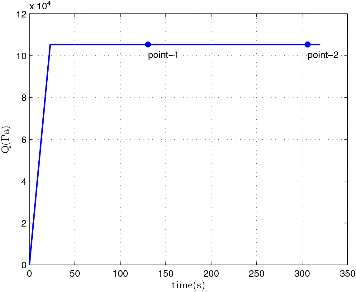
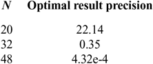
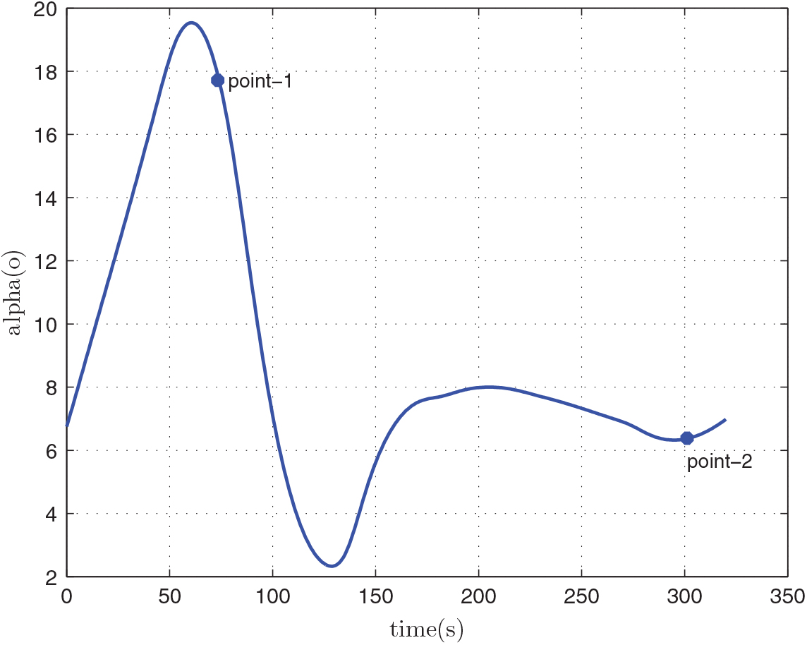
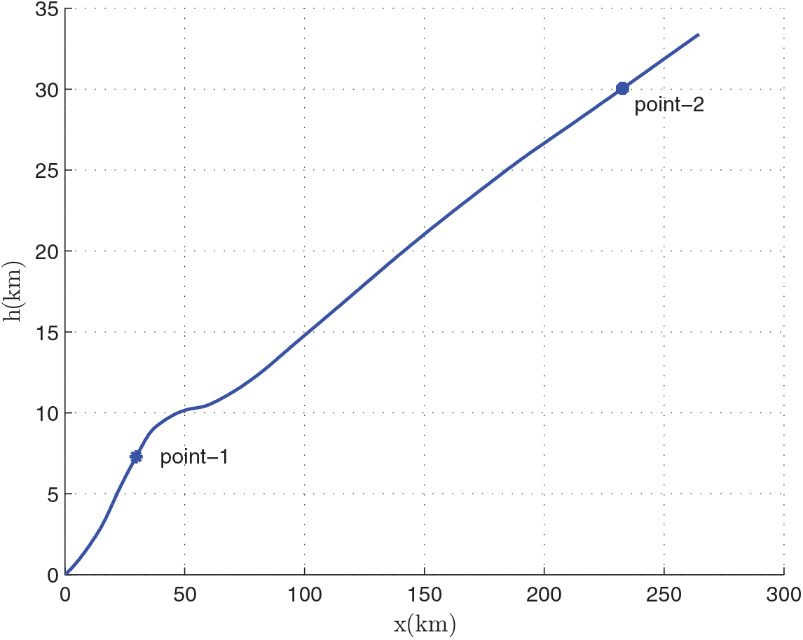
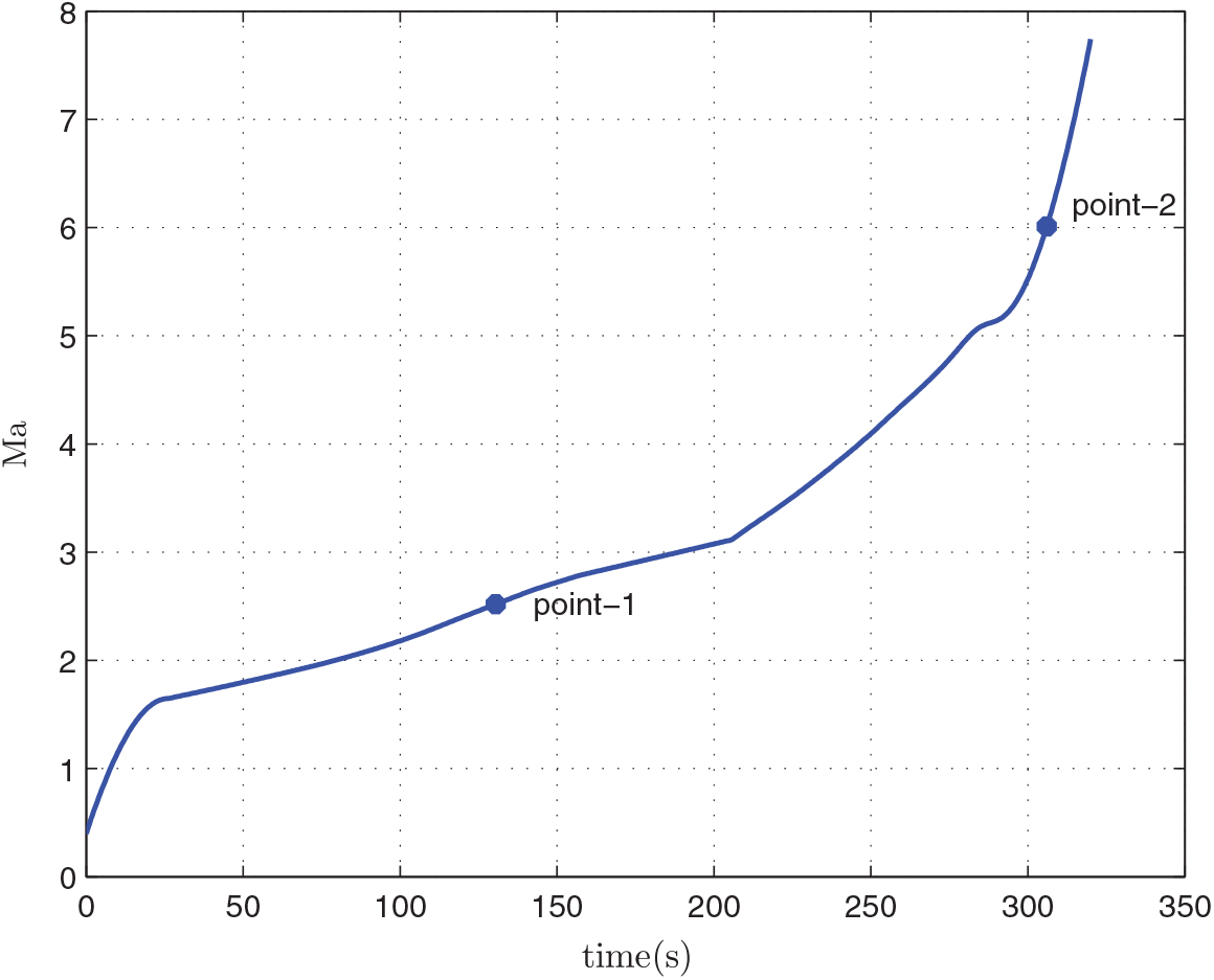
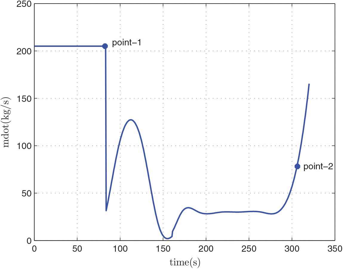
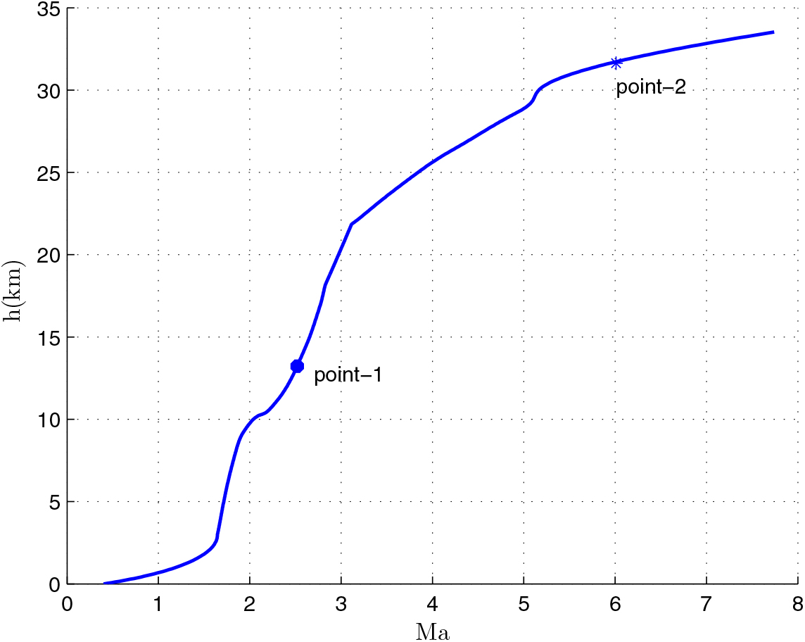
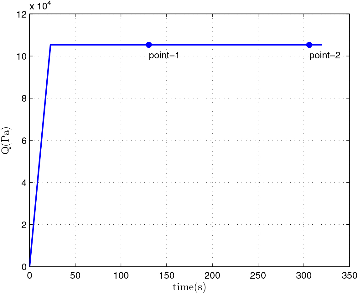
After the optimization, we can obtain the relevant results of the mass of the first-stage rocket m 01 = 38323.5 kg, the mass of propellant consumed prior to separation = 10420.8 kg, the separation Mach number Ma = 7.7414, the separation altitude h = 33528 m, the trajectory inclination angle at separation θ f = 3.12o and the takeoff-mass of the second-stage rocket m 02 = 7339.9 kg. Through three main iterations (GPM will sub-iterate itself), when N = 48, the designed optimal result meets the precision tolerance and ultimately reaches convergence, as shown in Table 6. Because of many range constraints, the convergence rate of GPM is slow by using MATLAB, about 704.01s. The optimization results are shown in Figs 5–10. In each figure, there are two points, where point-1 indicates that the ejection mode ends and the ramjet mode starts, and point-2 indicates that the ramjet mode ends, and the scramjet mode starts. Figure 5 shows the angle-of-attack curve, Fig. 6 shows the trajectory curve, Fig. 7 shows the Mach number curve and Fig. 8 shows the propellant flow before the separation. It can be seen that a spacecraft needs to burn more fuel to counteract gravity initially. As the speed increases and atmospheric density decreases, fuel consumption decreases. Figure 9 is the curve of altitude and Mach number, which illustrates that the flight envelope operates within Tables 3–5. Figure 10 is the dynamic pressure, which satisfies the constraint.
The convergence history
The angle-of-attack.
Flight trajectory.
Mach number.
Mass flow rate.
Altitude vs Mach number.
The flight dynamic pressure Q.
We can see that the flight Mach number keeps increasing when the time t < t f. Furthermore, the Mach number reaches the maximum when t = t f, and t f is the optimization end time of GPM optimization process. Thus, t f is the separation time of the first stage and the separation Mach number is the largest. We can also see that there is a peak and two valley values of angle-of-attack. At the beginning of the flight, angle-of-attack keeps increasing and begins to decrease when reaching a certain value. This is because the initial flight angle is small, and the angle-of-attack must continually increase to raise the trajectory angle of the spacecraft. At the end of the flight, in order to improve the flight speed, the engine thrust of the first-stage rocket needs to increase, but the geometry projection area of the inlet limits the air inflow. So, the angle-of-attack must be reduced. Because of the limitations of the rockets, the angle-of-attack will change again when the rocket reaches its maximum speed.
When the Mach number reaches Ma = 3.5, the rocket enters the flight range of constant dynamic pressure, the engine throttles quickly, the rocket starts to fly along a dynamic pressure path and the engine thrust will be determined by the actual dynamic pressure. From the control process of propellant mass flow rate, we can see that in the ejector mode, the propellant mass of the engine keeps the maximum flow rate at the average of 202. 3 kg/s, and at the average of 51.9kg/s in the ramjet mode and the scramjet mode. So, we can see that the propellant mass consumed is mainly concentrated in the ejector mode.
This global optimal processing of the GPM algorithm is beneficial to reduce the takeoff-mass m 01of the first stage, which has a higher economic value for larger payloads.
5.2 Simulation 2: The relationship of η and m 01
In order to better illustrate the relationship between the first-stage takeoff-mass m 01 and the inertia mass coefficient η with the same payload mass, this paper adopts the cubic spline fitting method to fit the curve of m 01 and η with a different payload mass m pl, as shown in Fig. 11.
The relationship between payload, η and m 01.
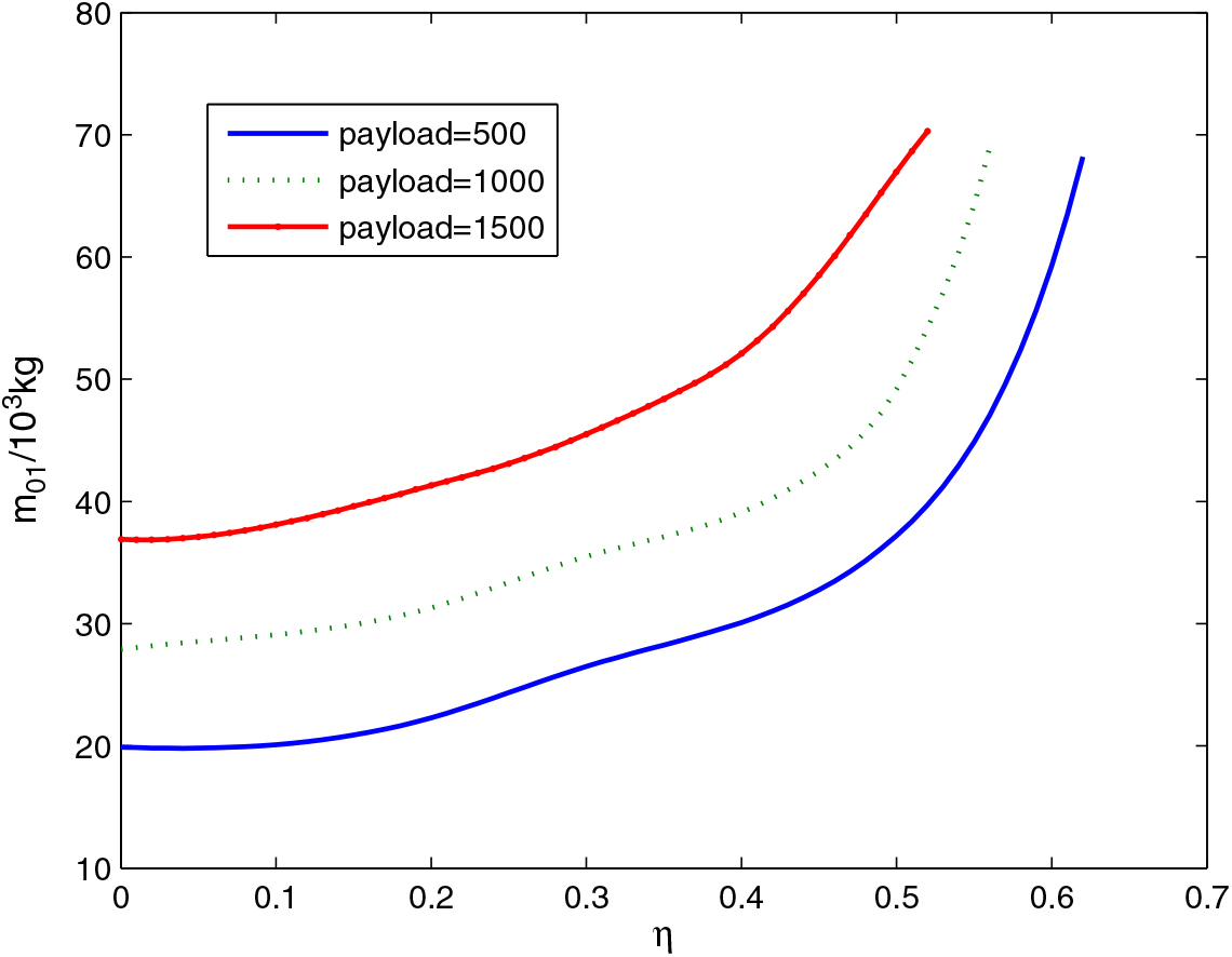
We can see that under certain conditions of the inertial mass coefficient, the larger the payload mass the larger the takeoff mass of the first-stage. This is the same with Ref. 6. However, the average takeoff-mass is smaller, about 530kg. When η is small, m 01 increases a little with the increase of η. When η increases to a certain value, η is the main part of the impact of the takeoff-mass m 01, which will increase rapidly with the increase of η.
In addition, when the takeoff-mass m 01 remains unchanged, the payload mass will decrease with the increase of the inertial mass coefficient η, and the spacecraft will lose its feasibility at the same time. So, for the feasibility of spacecraft, the inertial mass of the spacecraft must be controlled, especially the inertial mass of RBCC propulsion system.
5.3 Simulation 3: The relationship of Q max and m 01
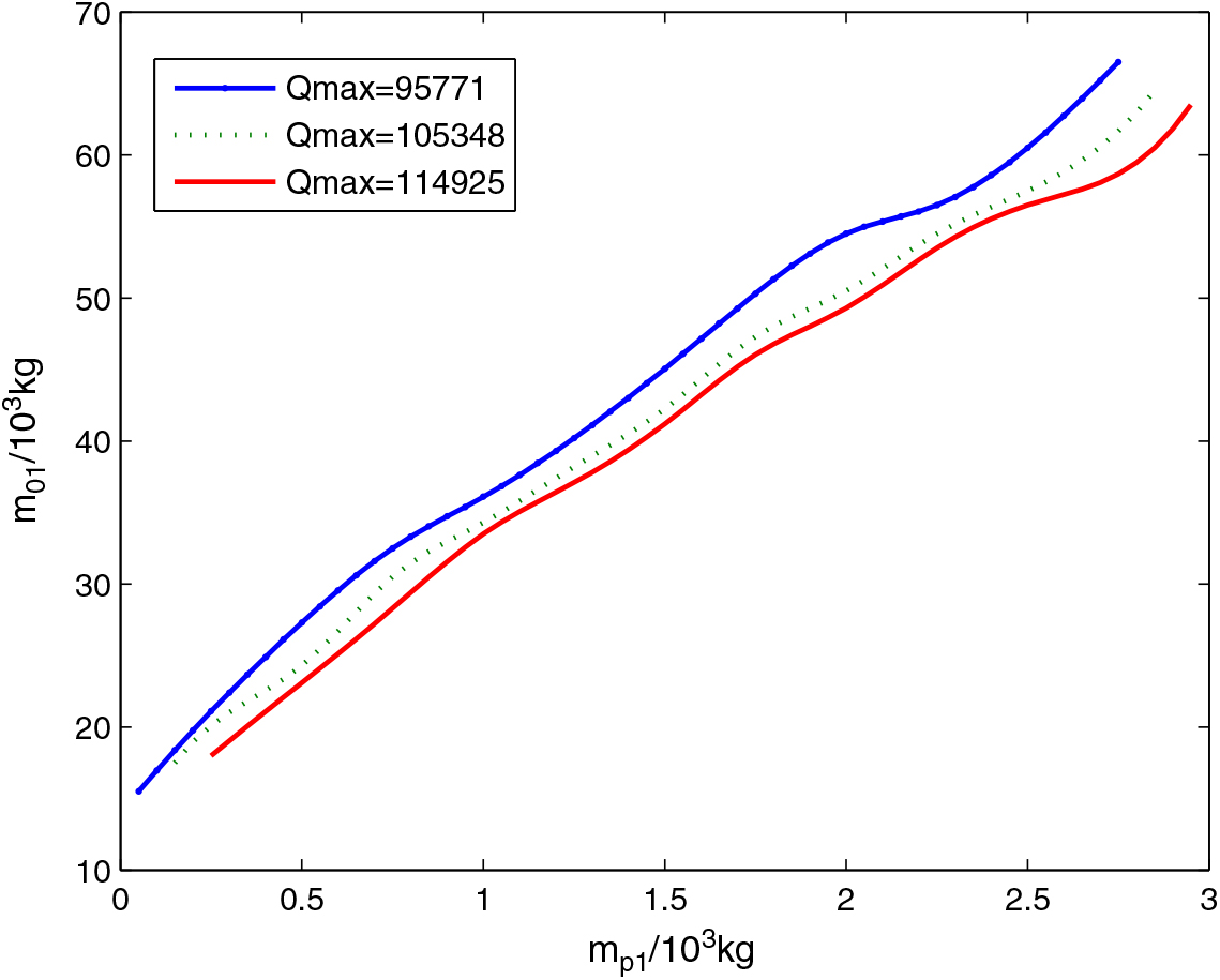
In order to guarantee that the RBCC engine works steadily in an optimal or stable state, when the spacecraft reaches a certain dynamic pressure, the RBCC-powered spacecraft usually keeps rising and accelerating with a constant dynamic pressure. Namely, the dynamic pressure of spacecraft remains Q = Q max unchanged in the ramjet mode and scramjet mode. In order to investigate the influence of the dynamic pressure Q max on m 01, we plot the curves of m p and m 01 when Q max= 95771, 105348 and 114925 pa, as shown in Fig. 12. It is clear in Fig. 12 that a higher dynamic pressure maximum Q max is beneficial to reduce the takeoff-mass of the first-stage. For a RBCC engine, the flight altitude and Mach number, whose relationship is determined by the dynamic pressure, directly affects the inhaled to air inlet mass flow rate and has a greater influence in the ramjet mode and scramjet mode. Because the dynamic pressure maintains a constant maximum Q max in the two modes.
The relation among Q max, payload and m 01.

From the point of the engine combustion, RBCC engine prefers a larger dynamic pressure, because under the condition of a certain capture area of air inlet, it can capture more air to increase the engine thrust. However, with the increase of dynamic pressure, the air resistance will increase, and the heat protection requirements of the spacecraft will also be increased.
So, a suitable dynamic pressure is needed for engine control. Appropriate dynamic pressure can throttle the mass flow appropriately. It can also effectively reduce the waste of engine performance caused by the negative angle-of-attack and improve the effective specific impulse. This is similar to the case of Ref. 6, but under the same conditions, our m 01is smaller.
6.0 CONCLUSIONS
Through the combination of mass and trajectory optimization, this paper reformulated the comprehensive performance optimization problem of the takeoff-mass of RBCC-RKT two-stage orbit spacecraft as a nonlinear optimal control problem. The GPM algorithm was used to solve the problem. In our model, the takeoff-mass of the second stage was considered as a constraint in the problem, which attenuates the convergence difficulty of the traditional iterative algorithm. There are fewer design parameters in our method. In this paper, integrated interpolation is done on the aerodynamic data, which created favourable conditions for the fast convergence of the algorithm. The numerical optimization results showed that the proposed method can well solve the problem of takeoff-mass estimation of two-stage-to- orbit spacecraft, and the separation Mach number and altitude can be optimized as well. Furthermore, the takeoff-mass of the second stage satisfies the inert mass fraction constraint of the first stage.
ACKNOWLEDGEMENTS
This work was supported in part by the Natural Science Foundation of China (61573197, 61703307), the University Youth Elite Support Plan Foundation of Anhui Province (gxyq2017045) and the Natural Science Foundation of Anhui Province (1808085MF183).
APPENDIX: THE COMPREHENSIVE INTERPOLATION METHOD OF I sp
According to the data in Tables 3–5 at different phases, there is no overlap in the Mach dimension so that they can be merged in a straightforward manner. For ease of presentation, this composite table is denoted as Table I sp. To obtain Table I sp, all sampled Mach numbers in the three tables are listed and form a two-dimensional empty table. Then the data of Tables 3–5 at the corresponding position of Table A1 is filled in.
The original data I sp
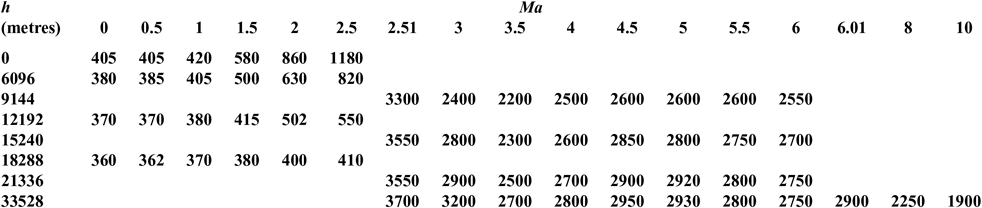
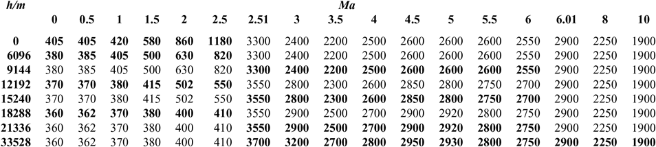
However, because the node coordinates of the three original tables do not match, there are many blanks spaces which can be divided into two categories: within or outside the scope of the original form. For example, the blank at (2Ma, 9144m) is within the scope of the original form, while the blanks at (2Ma, 21336m) and (4Ma, 6096m) are outside the scope of the original form. Different methods are adopted to cope with them. For the first category, internal linear interpolation is used. For example, the data at (2Ma, 6096m) and (2Ma, 12192m) is used to interpolate the data at (2Ma, 9144m). For the second category, we adopt the exterior extension method when the Mach number and altitude are beyond the scope of the data of the original table. We use the corresponding boundary data such as using the data at (2Ma, 18288m) to fill the blank at (2Ma, 21336m) and using the data at (4Ma, 9144m) to fill the blank at (4Ma, 6086m). It is noted that there are data corresponding to Mach 2.5 both in Tables 3 and 4, but not the same. We reset the sampled Mach number in Table 4 as 2.5 + ε, where ε is a small constant. The Mach number in Tables 5 and 6 is treated by the same method. So, comprehensive interpolation of the data at different stages can obtain a unified rectangular data table, namely Table A2. A two-dimensional curved surface of the data is shown in Fig. 4. So, a consistent two-dimensional interpolation method can be used to accelerate the convergence of the optimization algorithm.
The processed data of I sp