NOMENCLATURE
- b
-
blade semi-chord [m]
- B
-
3 × 2 matrix employed for the computation of the control input
- C
-
3 × 1 matrix employed for the computation of the control input
- c = 2b
-
blade chord [m]
- C(k)
-
Theodorsen function
- CG
-
blade centre of gravity
- CGf
-
control surface centre of gravity
- CL
-
blade sectional lift coefficient
- Cm
-
blade sectional pitching moment coefficient
- CP
-
blade sectional pressure coefficient
- F
-
transfer matrix relating βcont to [N βbl N θ] T
-
 ${\bf \overline{F}_c}$
-
2 × 1 array of the control blade root flap and pitch moments developed by the trailing-edge movable device
-
${\bf \overline{F}_{uc}}$
-
2 × 1 array of the blade root flap and pitch moments for the uncontrolled system
-
$\overline{F}_z$
-
rotating frame blade root non-dimensional vertical force
-
$\overline{F}_{z_a}$
-
rotating frame blade root non-dimensional aerodynamic vertical force
- [F z βbl F z θ ]
-
1 × 2 matrix relating z to
$\overline{F}_z$
- F z βcont
-
scalar transfer function relating βcont to
$\overline{F}_z$
-
${\widetilde{\bf \, F_z}}$
-
1 × 2 aeroelastic transfer matrix relating z to
$\overline{F}_z$
- FZR2/FZR3/FZR4/FZR5
-
blade root non-dimensional 2/rev, 3/rev 4/rev, 5/rev harmonics of the vertical force
- h
-
aerofoil position for the plunge motion [m]
- Ham
-
aerodynamic transfer matrix for the blade aeroelastic model
- h q(i)q(j)
-
elements of Ham
- Ib
-
blade flap moment of inertia [kg m2]
- If
-
blade feathering moment of inertia [kg m2]
- I f
-
control surface moment of inertia [kg m2]
- Is
-
blade flap static moment [kg m]
- J
-
quadratic-form scalar functional employed as cost function for the HHC algorithm
- k
-
reduced frequency, ωb/Ωr = ωb/U
- K
-
non-dimensional stiffness matrix for the blade aeroelastic model
- L
-
blade sectional lift [N/m]
- L
-
array of loads to be minimised
- L0
-
3 × 1 matrix related to the uncontrolled forces
- Lcont
-
3 × 1 matrix related to the control forces
- M
-
freestream Mach number
- M
-
mass matrix for the blade aeroelastic model [1/s2]
- M bl
-
blade mass [kg]
- M βbl
-
rotating frame blade root flapping moment [N m]
- M h βcont
-
rotating frame blade control surface hinge moment [N m]
- M f
-
mass of the control surface [kg]
- Mh
-
blade sectional control surface hinge moment [N]
- M θ
-
rotating frame blade root pitching moment [N m]
- MXR2/MXR3/MXR4/MXR5
-
blade root non-dimensional 2/rev, 3/rev 4/rev, 5/rev harmonics of the flap moment
- MYR2/MYR3/MYR4/MYR5
-
blade root non-dimensional 2/rev, 3/rev 4/rev, 5/rev harmonics of the pitch moment
- N βbl
-
rotating frame blade non-dimensional flapping moment
- N h βcont
-
rotating frame blade control surface non-dimensional hinge moment
- N c/4
-
blade sectional quarter chord pitching moment [N]
- N θ
-
rotating frame blade root non-dimensional pitching moment
- q
-
3 × 1 array of the DOFs for the blade aeroelastic model
- r
-
local blade radius [m]
-
$\bar{r} = 0.75R$
-
reference blade radius for the evaluation of the Theodorsen function [m]
- R
-
blade radius [m]
- R cont
-
scalar weighing factor for the control input
- Re
-
freestream Reynolds number
- t
-
time [s]
- U = Ωr
-
blade sectional airspeed [m/s]
- W
-
3 × 3 diagonal matrix for the weighing factors of the control outputs
- x
-
chord-wise position [m]
- X
-
transfer matrix relating z to [N βbl N θ] T
- xI
-
offset of of the blade centre of gravity with respect to the elastic axis [m]
- xP
-
offset of of control surface hinge axis with respect to its centre of gravity [m]
- z
-
2 × 1 array of the aeroelastic system response to the control input, namely the blade bending and pitch angles
- Z
-
2 × 2 transfer matrix of the aeroleastic model for the blade
-
$(\tilde{\cdot })$
-
variables in the Fourier transform domain
- α
-
angle-of-attack of attack [deg.]
- β
-
L-tab/flap deflection angle, positive upward [deg.]
- βbl
-
blade flapping angle [deg.]
- βcont
-
computed control input in terms for the L-tab or the TE flap, positive upward [deg.]
- β T cont
-
complex conjugate of βcont
- βf
-
angular position of the second segment in the ROM geometry [deg.]
- βw
-
angular position of the third segment in the ROM geometry [deg.]
- γ
-
Lock number
- ΔCP
-
pressure coefficient difference between the lower and the upper side of the blade section model
- θ = α
-
blade pitch angle [deg.]
- μ
-
helicopter advance ratio
- νβ
-
rotating natural frequency of the blade flap mode [/rev]
- νβf
-
non-dimensional torsional stiffness of the control surface [/rev]
- νθ
-
rotating natural frequency of the blade torsion mode [/rev]
- φ
-
phase angle of a generic complex parameter [deg.]
- χ w
-
chord enlargement induced by the L-tab rescaled with respect to the numerical chord
- ω
-
circular frequency [rad/s]
- Ω
-
rotor angular velocity [rad/s]


1.0 INTRODUCTION
The Gurney Flap (GF) was originally designed for the race car of Dan Gurney to increase the vehicle downforce generated by the rear inverted wing(Reference Katz1). Since then, the GFs have also attracted much attention of aircraft and rotorcraft designers as a very effective high-lift device. The GF effectiveness stems directly from its extreme simplicity: a flat edge attached to the Trailing Edge (TE) and perpendicular to the chord line.
Liebeck(Reference Liebeck2) was among the first to study the behaviour of Gurney flaps for aeronautical applications. On the basis of his experimental studies, he found that two counter-rotating vortices are generated behind the Gurney flap, as the flow is forced to turn around the perpendicular plate at the TE. The intersection point of the streamlines coming from the pressure and from the suction side is shifted away from the TE. As a consequence, the location of the Kutta condition is shifted downstream the TE, resulting in a net effect in terms of load that is equivalent to what can be obtained by a longer effective chord and a more cambered aerofoil. The interpretation proposed by Liebeck in Ref. 2 on the aerodynamic effects of GFs was confirmed by later studies. Experiments conducted on aeorfoils equipped with GFs highlighted the capability of these devices to significantly increase lift without severe drawbacks in terms of drag increment(Reference Kentfield3–Reference Maughmer and Bramesfeld10).
Recently, large interest was directed towards movable surfaces for aerodynamic performance improvement, alleviation of vibratory loads, flutter suppression and modification of the vortical wake. Several authors worked on the application of movable TE flaps on rotorcraft blades for vibratory load control (see Refs 11–16) and for the mitigation of negative effects associated with dynamic stall (see Refs 17–19). Since a GF has considerably less inertia than a traditional flap, smaller forces are expected to be required to actuate the system. As a consequence, a larger bandwidth can be achieved together with a reduced modification of the structural stiffness of the blades. Gerontakos and Lee(Reference Lee and Gerontakos20) performed experimental measurements on a NACA 0012 section equipped with fixed GF-like strips both on the pressure and on the suction side of the aerofoil. They showed that TE strips are suitable to improve performance of oscillating aerofoils, in dynamic stall conditions. Tang and Dowell(Reference Tang and Dowell21) validated a numerical model of a fixed GF on an oscillating aerofoil, against the the experiments of Ref. 20. Then, they showed through numerical computations that an oscillating Gurney flap brings additional benefits for deep-stall cases. Moreover, in Ref. 22, they carried out experiments on an oscillating NACA 0012 equipped with an oscillating GF, reaching the same conclusions of the numerical work (i.e. that an oscillating small strip located near the TE can be used for active aerodynamic flow control of a wing).
An interesting application of GF-like devices on rotorcraft, which is indeed the aim of the present study, concerns the alleviation of vibratory loads. Kinzel et al(Reference Kinzel, Maughmer and Duque23) performed several steady and unsteady numerical simulations for various flow conditions over a S903 section equipped with GFs, referred to as Miniature Trailing-edge Effectors (MiTEs). Such simulations gave an overview on the possible usage of MiTEs both to improve performance and to reduce vibratory loads on helicopter blades. Additionally, they investigated the effect of chord-wise positioning of the GF, showing that increased upstream positioning enlarges the hysteresis loop, degrades the lift enhancement, increases drag and decreases the nose-down pitching moment. Similar limits were found also in Refs 10 and 24–26. Matalanis et al(Reference Matalanis, Wake, Opoku, Min, Yeshala and Sankar27) carried out 2D and 3D simulations, together with experimental measurements, on a VR-12 section equipped with a deployable GF. They investigated the effects of the actuation frequency of the movable device on the vibratory moment coefficient, showing, by Computational Fluid Dynamics-Computational Structural Dynamics (CFD-CSD) coupled analyses on a model of the UH-60A, that significant reduction of vibratory loads can be achieved.
Despite the progress in the understanding the behaviour of these movable devices, the integration of an active GF on a helicopter blade is still a very challenging design problem. In particular, it is necessary to stow the deployable device, together with the actuation mechanism, at the TE, complying with weight and balance constraints related to the aeroelastic behaviour of the blades. Moreover, classical sliding actuation solutions, widely used for fixed wing GFs, are likely to undergo failures, under high centrifugal loads as those affecting rotor blades. Palacios et al(Reference Palacios, Kinzel and Overmeyer28) carried out several experimental tests to investigate the operation of MiTEs under centrifugal loads comparable to those encountered on rotor blades. They found that indeed such devices are capable to effectively operate in these conditions. Moreover the estimated power requirements of GF-like devices were found significantly lower than those of classical plain flaps.
In an attempt to overcome stowage and actuation issues at the same time, Zanotti et al(Reference Zanotti and Gibertini29,Reference Zanotti, Grassi and Gibertini30) proposed an L-shaped tab, i.e. a combination between a TE spoiler, namely a classical split flap, and a GF applied at the TE of a helicopter blade section. This concept has the additional advantage of locating the GF on the TE, therefore maximising its performance as shown in Refs 10 and 23–26. Experimental measurements carried out by Zanotti et al(Reference Zanotti and Gibertini29,Reference Zanotti, Grassi and Gibertini30) showed that this novel L-shaped tab could be exploited both downward deployed, as a GF, and upward deflected, as a classical TE flap, to mitigate the negative effects of dynamic stall.
To verify the capabilities of this novel device also for the control of vibratory loads in flow conditions far from those of dynamic stall, the behaviour of the unsteady loads due to oscillations of the aerofoil and of the L-tab was investigated numerically, by means of CFD. A preliminary numerical assessment of the behaviour of this device was reported in Ref. 31. Although effective, these simulations are computationally expensive and, as such, are not efficient during the design process and the development of control strategies. Thus, it is necessary to develop a ROM starting form CFD simulations. In Ref. 32, a physically based linear ROM for the first harmonic component of the unsteady lift and moment has been developed. The correct representation of the first harmonic is the primary interest of the ROM in view of the application of Higher Harmonic Controls (HHC) for vibration reduction. The model developed in Ref. 32 relies on physical flow features, such as the mean size of the Counter Rotating Vortices structures (CRV) developed past the L-tab discussed in this work.
The goal of this work is to assess the vibration reduction capabilities of the present L-tab in comparison to more classical devices, when installed on helicopter rotors, exploiting the aforementioned ROM to build up the aerodynamic transfer matrix of the aerostructural model for the blade. This comparison is carried out for several reduced frequencies k = ωb/U, ranging from 0 up to 0.6, a range that conveniently covers the typical frequencies of vibratory loads on rotorcraft blades: from 1/rev to 10/rev (see Ref. 33, Table 12.1). The HHC approach(Reference Johnson34) is herein employed to compute proper control laws for the L-tab and the TE flap, respectively, with the aim to reduce the blade root loads at one specific harmonic a time.
2.0 GEOMETRY AND REDUCED-ORDER MODEL FOR A BLADE SECTION EQUIPPED WITH THE L-TAB
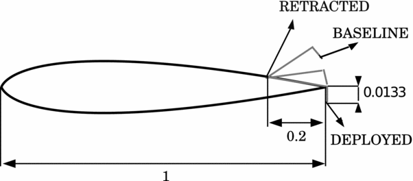
Figure 1 shows a schematic view of the L-tab geometry positioned on the TE of the aerofoil. The device resembles the one employed by Zanotti et al(Reference Zanotti, Grassi and Gibertini30) in their dynamic stall experiments.
Schematic of the NACA 0012 section equipped with the TE L-tab.

The L-tab chord-wise length is 20%c, while the height of its transverse prong is 1.33%c. The L-tab downward deflected protrudes 1.01%c from the aerofoil pressure side, being the geometry of the clean aerofoil cut before the TE. This is consistent with the GF heights found in literature, that commonly range between 0.5%c and 3%c (see e.g. Ref. 8). The L-tab is designed to be in rest position when it is rotated upward by 4°, measured starting from the position where the device is supported by the suction surface. In this condition, the end of the vertical prong lies aligned with the suction side corner of the TE. Therefore, the baseline configuration of the resulting aerofoil presents a divergent TE. Notice that the application of diverging TEs for the enhancement of the aerodynamic performance in transonic regime has been extensively treated in literature (see e.g. Refs 35 and 36). This fosters the suitability of the L-tab on rotor blades, where transonic flow conditions are often encountered.
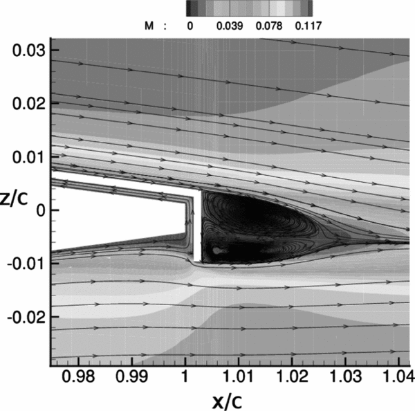
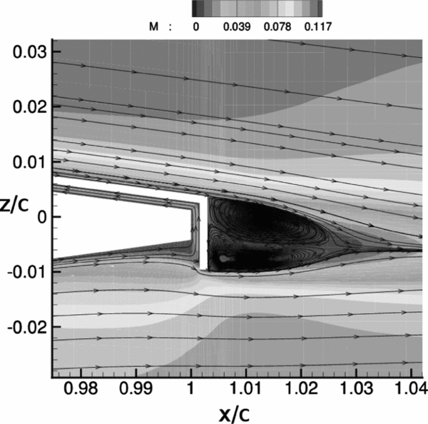
The development of a physically consistent ROM for the L-tab equipped NACA 0012 section is detailed in a previous work(Reference Motta and Quaranta32). The vortical region on the TE (see Fig. 2) can be considered an extension of the aerofoil that increases the effective chord and modifies the camber, resulting in the experienced lift and moment magnitude enhancement(Reference Wang, Li and Choi8). With the aim to obtain a model capable to correctly capture the near body physics induced by the L-tab, the aforementioned mean line modifications have to be accurately reproduced. The analytical formulation of Küssner and Schwarz(Reference Küssner and Schwarz37,Reference Fung38) , suitable for arbitrarily shaped mean lines under the hypothesis of small perturbation, is used as benchmark for the ROM development. The blade section with the movable L-tab is treated as a linear system with 3 Degrees Of Freedom (DOFs). These are namely pitch (α) and plunge (h/c) oscillations of the aerofoil, with the movable device in fixed position, and harmonic deflections of the L-tab (β, zero when downward deployed and positive for upward deflections), at constant angle-of-attack of the aerofoil.
Mach number flow field and streamlines close to the te of the L-tab equipped blade section, resulting from CFD simulations; angle-of-attack =
 $0\deg ,$
freestream Mach number M = 0.117, Reynolds number Re = 1 × 10⁶.
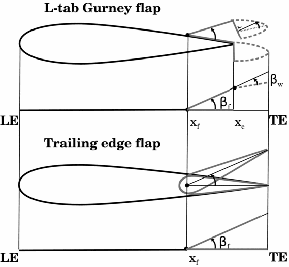
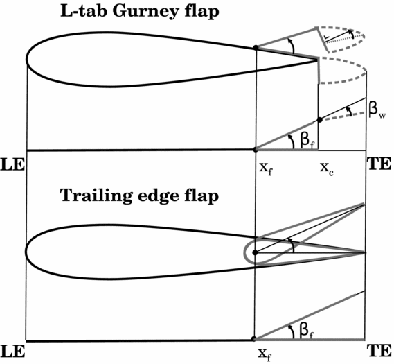
The aerofoil equipped with the L-tab is treated as a piece-wise-linear thin-line, which represents the aerofoil plus two movable surfaces: an aileron and a “virtual tab” (see Fig. 3). The first segment (from LE to x f) represents the baseline aerofoil. The second segment (from x f to x c) is representative of the flap portion of the L-shaped GF and is referred to as Equivalent L-Tab (ELT). The last segment (from x c to the end) represents the effect of the CRV developed by the L-tab and it extends beyond the TE of the aerofoil. This segment is referred to as Vortical structures Equivalent Trim Tab (VETT).
Thin line geometry for the ROMs; L-tab GF with the CRV (top) and classical plain TE flap (bottom).
3.0 COMPARISON BETWEEN THE L-TAB GURNEY AND CLASSICAL TE FLAP
Modifications in the effective camber equivalent to those induced by the L-tab could be obtained with a classical TE flap. Nevertheless, whereas the same shape of the mean line can be potentially achieved both with the present L-tab, and with a classical TE flap, the loads generated by the two configurations are expected to be different. Indeed, the CRV past the L-tab do not directly contribute to the generation of the aerodynamic loads, that is, such vortical structures do not act as a lifting surface, not being a solid body. Rather, the CRV modify the pressure distribution along the aerofoil, ultimately affecting the resulting aerodynamic loads. On the other hand, a classical TE flap behaves indeed as a lifting surface, capable to develop aerodynamic loads by itself. Of course, also the upstream effect in the pressure distribution is expected to be different, when dealing with a TE flap, rather than with a GF-like device.
It appears interesting to gain an overview on the behaviour of the aerodynamic loads potentially generated by these two different TE configurations. This allows to preliminary estimate which solution among the present L-tab and a classical flap is more suitable to reduce vibratory loads at different frequencies.
Thin-line analytical low-order models, as the one reported in Section 2, are appropriate for this comparison, since these allow for a rapid and straightforward computation of the aerodynamic loads, given the reference geometry and the motion law. Figure 3 shows a schematic comparison between the two movable devices under consideration and the corresponding thin-line geometry. Notice that the flap is thought to take into account also the chord extension associated to the CRV past the L-tab. Therefore, the second segment in the equivalent geometry of the flapped section has length equal to that of the ELT plus the VETT, as is shown in Fig. 3. The hinge of the flap has the same location of that of the L-tab. The values of β f and xc computed with the identification procedures performed on the L-tab are used for the model of the TE flap as well. Of course, this latter configuration does not present the DOF related to β w , i.e. the additional motion of the VETT with respect to the ELT.
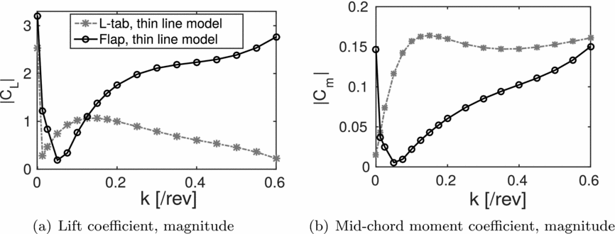
Figure 4(a) reports the magnitude of the lift coefficient versus the reduced frequency, including k = 0, obtained with the Küssner-Schwarz (KS)-based models for the two TE configurations. The L-tab grants larger lift in the range 0.05 ⩽ k ⩽ 0.125; the TE flap seems to provide higher values of normal force for k < 0.05 and for 0.125 < k < 0.6. A slightly larger value of lift is achieved with the TE flap for k = 0 as well. This difference is due to the fact that the added mass effect, which is influential at large reduced frequency, is larger for the TE flap due to a larger extension of the solid moving surface.
Magnitude of the lift and pitching moment coefficients vs the reduced frequency. Comparison between the L-tab and the flap models at β = 1 deg. and β = sin(ωt) deg.; M = 0.117, Re = 1 × 10⁶.
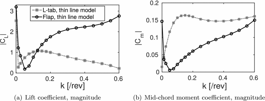
Figure 4(b) shows the magnitude of the mid-chord moment coefficient for the L-tab and the flap models. Notice that for k > 0.0125, the moment magnitude obtained with the L-tab is significantly larger with respect to the TE flap. At k = 0.0125, the two TE configurations seem to provide the same pitching moment. A larger pitching moment is obtained at k = 0 with the TE flap. Here, the fact that the loads on the L-Tab are the effect of the movement of two surfaces, included the virtual trim tab represented by the VETT, is modifying significantly the behaviour at large reduced frequency.
The ultimate selection of the control surface to be employed is somehow tricky, since several aspects have to be taken together under consideration. Of course, the choice cannot be based merely on the magnitude of lift and moment coefficients developed for steady-state configurations or small-amplitude oscillations but must take into account also technological aspects. The preliminary comparison reported in this section has the primary aim of showing that both the steady and the unsteady airloads developed by the present L-tab are similar to those generated by a classical TE flap configuration, widely diffused in literature, at least up to k = 0.15.
It appears useful to recall that, among the additional operations of such movable devices on rotor blades, the performance enhancement and the dynamic stall alleviation are of primary interest. In this context, acting on the pitching moment appears to be more effective, rather than on the lift, since by acting directly on the blade twist, the angle-of-attack can be locally controlled and properly set to the values required (e.g. for static load balance or to avoid the stall onset). Furthermore, considerations concerning actuation and stowage requirements, as those reported in the work of Palacios(Reference Palacios, Kinzel and Overmeyer28), affect the ultimate choice of the TE device for the rotor blade. With this regard, the employment of the L-tab appears to be very promising, since its small weight features should allow for lower power and in turn smaller and lighter actuation systems, with respect to those required for classical TE flaps.
4.0 AEROELASTIC MODEL FOR THE BLADE SECTION WITH THE L-TAB
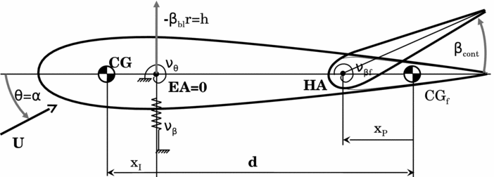
An analytical formulation based on the typical section model(Reference Bisplinghoff, Ashley and Halfman39) is used to investigate the aeroelastic response of the blade section equipped either with the L-tab or with a classical flap. Details of this largely employed approach can be found, for instance, in chapter 16 in the textbook of Johnson(Reference Johnson40). The aerostructural model has 3 DOFs, namely pitch and plunge oscillations of the aerofoil, in addition to the rotation of the control surface, βcont, positive upward. According to classical approaches adopted to model the blade dynamics(Reference Johnson40), the plunge motion is written as a function of the local bending, namely h = −βbl r, being βbl the flapping angle and r the local radius on the blade. Consistently with the classical notation, the pitch of the blade is referred to as θ. The resulting 3 × 1 complex array of the blade DOFs is therefore q = [βbl θ βcont] T .
The aeroelastic model is sketched in Fig. 5. The bending stiffness is represented by a translational spring of non-dimensional stiffness νβ, equivalent to the rotating natural frequency of flap mode for the blade model. On the other hand, the torsional stiffness is represented by means of a torsional spring of non-dimensional stiffness νθ, equivalent to the rotating natural frequency of the torsion mode for the blade model. The TE movable device has non-dimensional torsional stiffness νβf. The blade mass is referred to as M bl, whereas its flap and feathering moments of inertia are referred to as Ib and If , respectively. The bending static moment of the blade is referred to as Is . To keep the consistency with the stiffness quantities, the blade mass properties are made dimensionless with respect to the flap moment of inertia Ib (Reference Johnson40). The mass M f and moment of inertia I f of the TE control surface are herein assumed negligible with respect to those of the blade. This hypothesis is clearly true for the L-tab.
Sketch of a typical section model with a TE control surface.
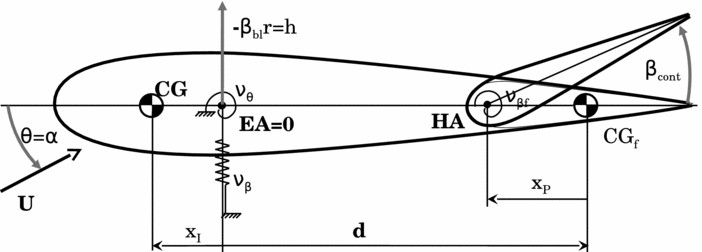
The origin of the x chord-wise coordinate is located on the blade elastic axis EA, namely at the blade quarter-chord. The centre of gravity CG is located at distance xI upstream the elastic axis. The control surface centre of gravity CGf is located at distance d from the elastic axis. The offset of the flap hinge axis HA with respect to its centre of gravity corresponds to xP .
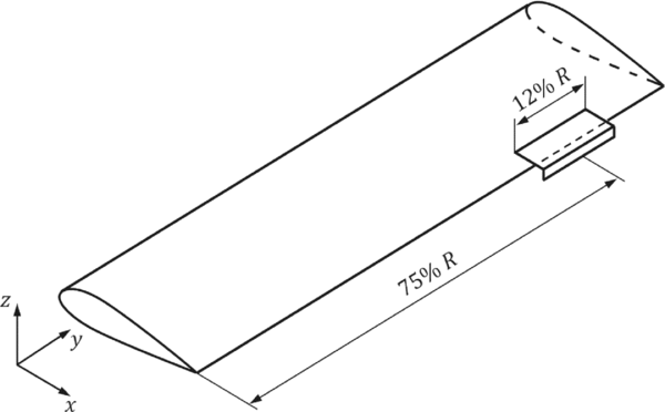
The control surface is supposed to cover the 12% of the blade length and to be centred at the 75% of the blade span, as shown in Fig. 6.
Sketch of the blade model equipped with the L-shaped control surface.
The resulting non-dimensional system of equations for a single rotor blade is written in the frequency domain ω as:
 $$\begin{equation}
\left[-\omega ^2{\bf M} + {\bf K}\right] \; {\bf q}(\mathrm{j}\omega ) = \gamma
\left\{ \begin{array}{c}
N_{\beta _{{\rm bl}}} \\[5pt]
N_{\theta } \\[5pt]
N_{h_{\beta _{{\rm cont}}}} \end{array}\right \},
\end{equation}$$
where M is the mass matrix, K is the stiffness matrix, and q = [βbl θ βcont] T the aforementioned 3 × 1 array of the blade DOFs, and γ the Lock number, i.e. the ratio between the aerodynamic forces and the inertial forces (see Ref. 40). No structural damping terms are introduced in the model. The symmetrical mass matrix is(Reference Johnson40):
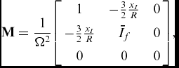 $$\begin{equation}
{\bf M} = \frac{1}{\Omega ^2} {\left[
\begin{array}{c@{\quad}c@{\quad}c}
1 & -\frac{3}{2}\frac{x_I}{R} & 0 \\[5pt]
-\frac{3}{2} \frac{x_I}{R} & \bar{I}_f & 0\\[5pt]
0 & 0 & 0
\end{array}\right]},
\end{equation}$$
where xI
is the offset of the blade centre of gravity with respect to its feathering axis (negative upstream the feathering axis) and
 $\bar{I}_f$
is the ratio between the feather moment of inertia If
and the flap moment of inertia Ib
.
The symmetrical stiffness matrix, also made dimensionless with respect to the blade flap moment of inertia, is(Reference Johnson40):
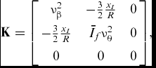 $$\begin{equation}
{\bf K} = {\left[
\begin{array}{c@{\quad}c@{\quad}c}
\nu _{\beta }^2 & -\frac{3}{2}\frac{x_I}{R} & 0 \\[5pt]
-\frac{3}{2}\frac{x_I}{R} & \bar{I}_f \nu _{\theta }^2 & 0\\[5pt]
0 & 0 & 0
\end{array}\right]},
\end{equation}$$
recalling that νβ is the rotating natural frequency of the flap mode and νθ is the rotating natural frequency of the pitch mode, both expressed in /rev.
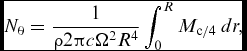
N βbl , N θ, and N h βcont are the non-dimensional blade aerodynamic flapping, pitching and flap hinge moments, respectively. The airloads on the blade resulting are obtained integrating the sectional lift L, the quarter-chord pitching moment M c/4 and hinge moment Mh , i.e.
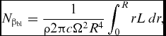 $$\begin{equation}
N_{\beta _{{\rm bl}}} = \frac{1}{\rho 2\pi c \Omega ^2 R^4} \int _0^R r L \: dr,
\end{equation}$$\\
 $$\begin{equation}
N_{\theta } = \frac{1}{\rho 2\pi c \Omega ^2 R^4} \int _0^R M_{{\rm c/4}} \: dr,
\end{equation}$$\\
 $$\begin{equation}
N_{h_{\beta _{{\rm cont}}}} = \frac{1}{\rho 2\pi c \Omega ^2 R^4} \int _0^R M_h \: dr ,
\end{equation}$$
 $k = \frac{\omega b}{\Omega r}$
. Additionally, Section 2 shows that the geometrical and motion parameters of the unsteady loads computed for the L-Tab ROM slightly change with the reduced frequency. As a result, it should be required to evaluate these loads at each of the stations along the span. However, consistently with the approaches presented in Ref. 40, an approximated model can be obtained using for the entire blade the reduced frequency evaluated at
 $\bar{r} = 0.75R$
; therefore,
 $k = \frac{\omega b}{\Omega \bar{r}}$
. Using the developed ROMs for the unsteady aerodynamic forces, it is possible to compute the aerodynamic transfer matrix Ham
,
 $$\begin{equation}
{\left\lbrace \begin{array}{c}N_{\beta _{{\rm bl}}} \\[5pt]
N_{\theta } \\[5pt]
N_{h_{\beta _{{\rm cont}}}} \end{array}\right\rbrace } = {\bf H_{am}} {\bf q}
\end{equation}$$
In conclusion, Equation (1) can be written as
 $$\begin{equation}
\left[-\omega ^2{\bf M} + {\bf K} \;- \gamma {\bf H_{am}}(k) \right]{\bf q}({\rm j}\omega ) = {\bf Z}(\mathrm{j}\omega ) {\bf q}({\rm j}\omega ) = {\bf 0}
\end{equation}$$
Since βcont is actually a control input, the aeroelastic transfer matrix Z(jω) of Equation (8) is split as follows:
 $$\begin{equation}
{\bf Z}(j\omega ) = {\left[
\begin{array}{c@{\quad}c}
\bf Z_{\beta _{{\rm bl}}\theta } & {\bf Z}_{\beta _{{\rm cont}_{(\beta _{{\rm bl}}\theta )}}}^T\\[5pt]
{\bf Z}_{\beta _{{\rm cont}_{(\beta _{{\rm bl}}\theta )}}} & Z_{\beta _{{\rm cont}}}
\end{array}\right]}
\end{equation}$$
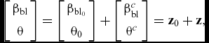
to separate the free degrees of freedom from the input βcont. The system response array [βbl θ] T may be expressed as:
 $$\begin{equation}
{\left[\begin{array}{c}\beta _{{\rm bl}} \\[5pt]
\theta \end{array}\right]} = {\left[\begin{array}{c}\beta _{{\rm bl}_0}\\[5pt]
\theta _0 \end{array}\right]} + {\left[\begin{array}{c}\beta ^c_{{\rm bl}}\\[5pt]
\theta ^c \end{array}\right]} = {\bf z}_0 + {\bf z},
\end{equation}$$
where z 0 is the uncontrolled response and z the system response to the control input(Reference Johnson34,Reference Patt, Liu, Chandrasekar, Bernstein and Friedmann41) . Accordingly, Equation (8) can be written as:
 $$\begin{equation}
{\bf Z}_{\beta _{{\rm bl}}\theta } {\left[\begin{array}{c}\beta _{{\rm bl}} \\[5pt]
\theta \end{array}\right]} = - {\bf Z}_{\beta _{{\rm bl}}\theta } {\left[\begin{array}{c}\beta _{{\rm bl}_0} \\[5pt]
\theta _0 \end{array}\right]} - {\bf Z}_{_{(\beta _{{\rm bl}}\theta )}\beta _{{\rm cont}}}^T \; \beta _{{\rm cont}}
\end{equation}$$
The system response can ultimately be expressed as:
 $$\begin{equation}
{\bf z} = - {\bf z}_0 - {{\bf Z}_{\beta _{{\rm bl}}\theta }}^{-1} {\bf Z}_{\beta _{{\rm cont}_{(\beta _{{\rm bl}}\theta )}}}^T \; \beta _{{\rm cont}}
\end{equation}$$
According to the classical notation employed for the HHC formulations(Reference Friedmann and Millott11,Reference Johnson34,Reference Patt, Liu, Chandrasekar, Bernstein and Friedmann41) , Equation (12) can be written as
 $$\begin{equation}
{\bf z} = - {\bf z}_0 - {\bf T} \; \beta _{{\rm cont}},
\end{equation}$$
where T = Z
βblθ
−1
Z
T
βcont(βblθ)
. As a result, the control force in terms of flap and pitch moments at the blade root, developed by the TE device, is
 $\overline{{\bf F}}_{{\rm c}} = - {\bf T} \; \beta _{{\rm cont}}$
Consistently, the flap and pitch moment at the blade root for the uncontrolled system can be written as
 ${\bf \overline{F}_{{\rm uc}} = {\bf z}_0}$
.
Among the load components which most affect the vibration transmitted from the blades to the rotor hub there is the vertical force Fz
. The aerodynamic vertical force on the blade is computed by assuming the lift as almost parallel to the z axis. The lift computed for each of the blade sections, by taking into account the local speed and reduced frequency, is integrated to obtain the blade root non-dimensional vertical aerodynamic force
 $\overline{F}_{z_{{\rm a}}}$
:
 $$\begin{equation}
\overline{F}_{z_{{\rm a}}} = \frac{1}{\rho \pi R^4 \Omega ^2} \int _0^R L \: dr = \frac{1}{\rho \pi R^4 \Omega ^2} \left( -[F_{z_{\beta _{{\rm bl}}}} \;\; F_{z_{\theta }}] \; {\bf z} + F_{z_{\beta _{{\rm cont}}}} \beta _{{\rm cont}} \right)
\end{equation}$$
F
z
βbl
gives the vertical force for a unitary bending rotation of the blade, F
z
θ
provides the vertical force for a unitary pitch rotation of the blade, whereas F
z
βcont
determines the vertical force for a unitary rotation of the control surface. Notice that the first term of the right-hand side in Equation (14) is opposite in sign with respect to the second term. As an example, by imposing a downward rotation to the control surface, the blade undergoes an upward flapping motion, which in turn leads to negative aerodynamic forces generated by plunge and pitch oscillations. That is, the aerodynamic vertical force related to flapping and pitching motions of the blade is opposite in sign with respect to the vertical force generated by deflecting the control surface. The final expression for the non-dimensional vertical force
 $\overline{F}_z$
at the blade root includes the blade bending inertial force. Therefore,
 $$\begin{equation}
\overline{F}_z =\frac{1}{\rho \pi R^4 \Omega ^2} \left( -[F_{z_{\beta _{{\rm bl}}}} \;\; F_{z_{\theta }}] \; {\bf z} + F_{z_{\beta _{{\rm cont}}}} \; \beta _{{\rm cont}} -\Omega ^2 I_s\:\beta _{{\rm bl}} \right),
\end{equation}$$
where the bending inertial force Ω2 Is βbl is again opposite in sign with respect to the blade flapping induced by the rotation of the control surface.
5.0 HIGHER HARMONIC CONTROL FOR BLADE VIBRATION REDUCTION
The HHC approach(Reference Friedmann and Millott11,Reference Johnson34,Reference Patt, Liu, Chandrasekar, Bernstein and Friedmann41) is employed to compute the potential vibration reduction capabilities of the L-tab, compared to those provided by the TE flap described in Section 3. According to Johnson(Reference Johnson34), three primary features characterise HHC algorithms: a linear, quasi-static frequency domain model of the helicopter response; an identification procedure carried out by means of a least squares or a Kalman filter method; the employment of a quadratic-form cost function. The HHC algorithm herein proposed presents indeed all of these properties.
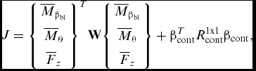
Since the HHC approach is conceived to minimise vibratory loads for one specific frequency at time(Reference Friedmann and Millott11), proper control inputs are computed separately for the 2/rev, 3/rev, 4/rev and 5/rev loads. A cost function J including the blade root flap and pitch moments, in addition to the vertical shear, is employed for computing the optimal control input βcont to be applied. Namely, the functional contains the 3 × 1 array
 $ {\bf L} = [\overline{M}_{\beta _{{\rm bl}}} \;\; \overline{M}_{\theta } \;\; \overline{F}_z]^T$
:
 $$\begin{equation}
J = {\left\lbrace \begin{array}{c}\overline{M}_{\beta _{{\rm bl}}} \\[5pt]
\overline{M}_{\theta } \\[5pt]
\overline{F}_z\end{array}\right\rbrace }^{T}{\bf W} {\left\lbrace \begin{array}{c}\overline{M}_{\beta _{{\rm bl}}} \\[5pt]
\overline{M}_{\theta } \\[5pt]
\overline{F}_z \end{array}\right\rbrace } + \beta ^T_{{\rm cont}}R_{{\rm cont}}^{1{\rm x}1}\beta _{{\rm cont}},
\end{equation}$$
where the transpose operation involves also the computation of the complex conjugate. Accordingly, β T cont is the complex conjugate of βcont. The diagonal matrix W specifies the weights for the controlled variables, whereas the scalar R cont weights the control input authority. The array of the loads in Equation (16) has to be expressed as a function of the control input βcont. For convenience, the following matrices are introduced:
 $$\begin{equation}
{\widetilde{\bf F_z}}= \frac{1}{\rho \pi R^4 \Omega ^2} \left( [F_{z_{\beta _{{\rm bl}}}} \;\; F_{z_{\theta }}] + [\Omega ^2 I_s\;\;0] \right),
\end{equation}$$\\
 $$\begin{equation}
{\bf B}= {\left\lbrace \begin{array}{c}\bf 0 \\[5pt]
{\widetilde{\bf F_z}}\end{array}\right\rbrace },
\end{equation}$$\\
 $$\begin{equation}
{\bf C} = {\left\lbrace \begin{array}{c}-{\bf Z}_{\beta _{{\rm cont}_{(\beta _{{\rm bl}}\theta )}}}^T \\[5pt]
F_{z_{\beta _{{\rm cont}}}} \end{array}\right\rbrace },
\end{equation}$$
The following matrices are also introduced, to conveniently express J.
 $$\begin{equation}
{\bf L}_0 = {\left\lbrace \begin{array}{c}\overline{{\bf F}}_{{\rm uc}} \\[5pt]
0 \end{array}\right\rbrace } - {\bf B}\; {\bf z}_0,
\end{equation}$$\\
 $$\begin{equation}
{\bf L_{{\rm cont}}} = -{\bf B} {{\bf Z}_{\beta _{{\rm bl}}\theta }}^{-1} \; {\bf Z}_{\beta _{{\rm cont}_{(\beta _{{\rm bl}}\theta )}}}^T + {\bf C}
\end{equation}$$
The 3 × 1 array L, containing the loads to be minimised, can now be written as a function of βcont as follows:
 $$\begin{equation}
{\bf L} = {\bf L}_0 + {\bf L_{{\rm cont}}} \; \beta _{{\rm cont}}
\end{equation}$$
As a result, the cost function of Equation (16) reads:
 $$\begin{equation}
J = \left({\bf L}_0^T + \beta ^T_{{\rm cont}} {\bf L_{{\rm cont}}}^T \right) {\bf W} \left({\bf L}_0 + {\bf L_{{\rm cont}}} \; \beta _{{\rm cont}} \right) + \beta ^T_{{\rm cont}}R_{{\rm cont}}\beta _{{\rm cont}}
\end{equation}$$
By imposing dJ/dβcont = 0, the control input can be computed as follows:
 $$\begin{equation}
\beta _{{\rm cont}} = - \left( {\bf L_{{\rm cont}}}^T {\bf W} {\bf L_{{\rm cont}}} + R_{{\rm cont}} \right)^{-1}\; \left({\bf L}_0^T {\bf W} {\bf L}_0 \right)
\end{equation}$$
A blade model for a hingeless Bo-105 rotor is herein used as test application for the present control system. The values of the blade model properties, used to evaluate the matrices of the aeroelastic system, are reported in Table 1.
Geometrical, inertial and elastic main properties of the blade for a Bo-105 rotor model
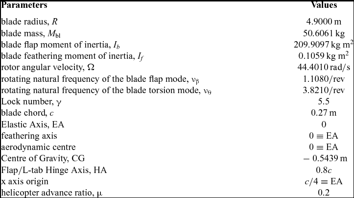
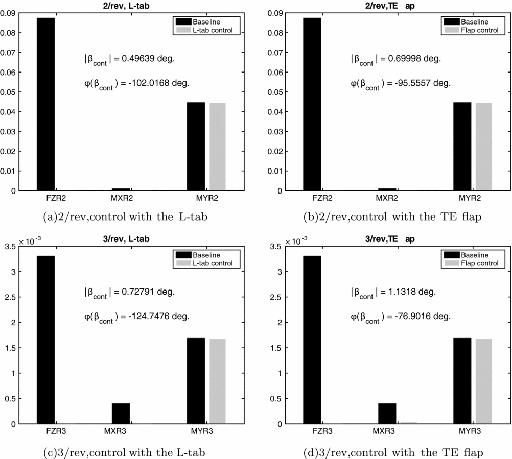
Figure 7 reports the vibratory blade root loads in the rotating frame corresponding to the baseline and controlled configurations—with both the L-tab and the TE flap models—for the 2/rev and 3/rev harmonic components. The values of the control input magnitude and phase, obtained by minimising the cost function in Equation (23), are also reported. Both the L-tab and the TE flap are found to break down almost the 100% of the vertical force and of the bending moment. On the other hand, the root pitching moment appears substantially unaffected by the movable device. The optimal control input of the L-tab is slightly smaller than that of the TE flap. Notice that such values of the control inputs are not dissimilar to those obtained by Chopra(Reference Roget and Chopra14,Reference Milgram and Chopra42) , with analogous TE solutions. The phase angle of the control input at 2/rev and 3/rev lies in the range [ − 125, − 75] deg., for both the L-tab and the TE flap.
Rotating frame blade root 2/rev and 3/rev harmonic components of vertical force (FZ), bending (MX) and pitching (MY) moments with and without the addition of the movable device, controlled with the HHC approach; μ = 0.2.
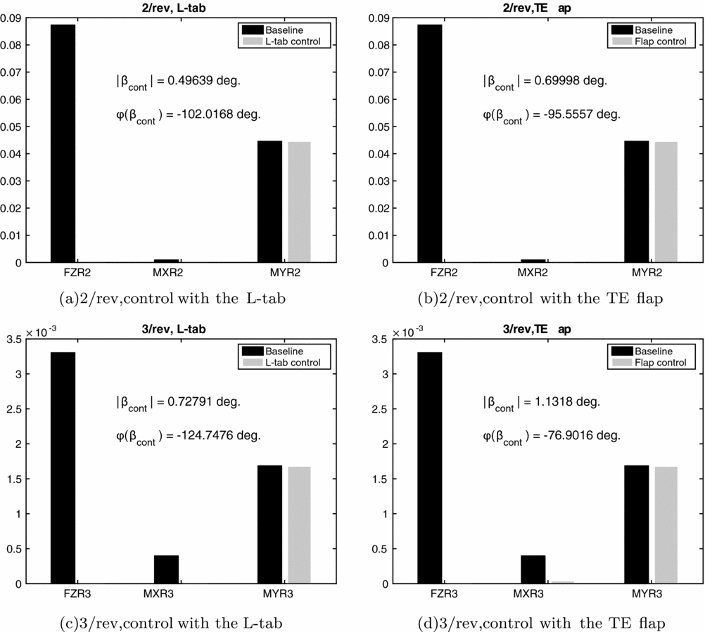
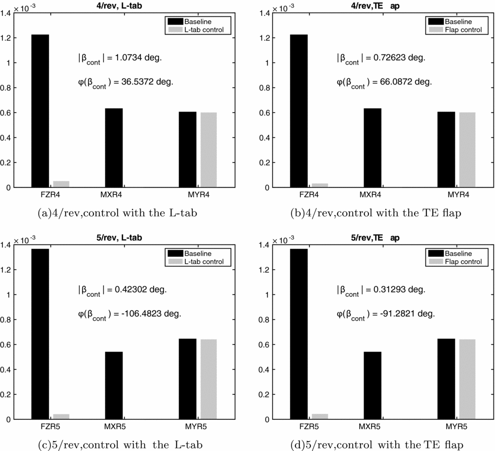
Figure 8 shows the vibratory rotating frame blade root loads corresponding to the baseline and to the configuration with the L-tab and TE flap models, for the 4/rev and 5/rev harmonic components. The control input magnitude and phase, obtained by minimising the cost function of Equation (23), are also reported. The blade root flapping moments are almost completely canceled, whereas the vertical forces undergo reductions superior to 90%. Similarly to what observed for the 2/rev and 3/rev harmonics, no significant effects of the control devices on the blade root pitching moment can be obtained. The optimal control input amplitude obtained for the L-tab is slightly larger with respect to that of the TE flap. The input control amplitude is again not dissimilar to the values computed by Chopra(Reference Roget and Chopra14,Reference Milgram and Chopra42) on a TE flap employed for rotorcraft vibration reductions. The phase angle of the control inputs is positive for the 4/rev harmonic and negative for the 5/rev component.
Rotating frame blade root 4/rev and 5/rev harmonic components of vertical force (FZ), bending (MX) and pitching (MY) moments with and without the addition of the movable device, controlled with the HHC approach; μ = 0.2.
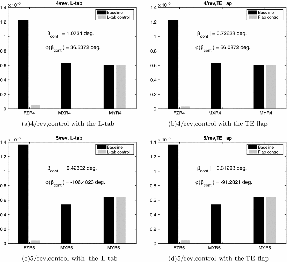
As expected, both the L-tab and the TE flap are found not capable to alleviate the blade root pitching moment. This is due to the large torsional stiffness, typical of most rotor blades. The local flapping caused by the rotation of the movable device propagates along the entire span, providing a significant magnification factor to the action of the control surface. This does not occur for the blade torsion. To obtain a more effective action on the blade twist, which in turn is transmitted to the main rotor through the pitch links, a distribution of several L-tabs or TE flaps along the span should be employed, see for instance the work of Lemmens(Reference Lemmens, Erdelyi and Olbrechts43). Alternatively, a new blade, with a significantly smaller torsional stiffness, should be conceived, to allow for the propagation of the local blade torsion, induced by the control surface, along the entire span.
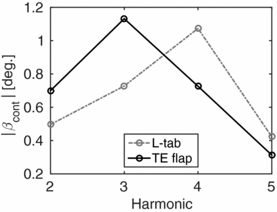
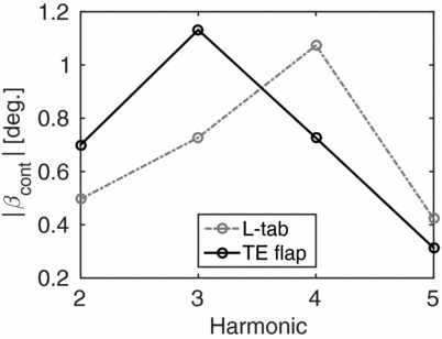
Table 2 reports the values of the reference reduced frequency, computed at the 75% of the blade span as k = ωb/Ω0.75R, being ω the /rev frequency, ranging from 2/rev to 5/rev. In this way, it is possible to immediately relate the results discussed in this section with those reported in Fig. 4(a). Notice that for 2/rev and 3/rev k < 0.125. Therefore, according to Fig. 4(a) the L-tab provides larger values of lift, for equal rotations of the movable device. This is consistent with the results reported in Fig. 7, in terms of the computed control input amplitude. Indeed, to achieve almost the same control force, and in turn load alleviation, the TE flap requires a larger rotation amplitude with respect to the L-tab. On the other hand, for 4/rev and 5/rev the corresponding reference k is greater than 0.125. Consistently, almost analogous reductions in the vertical force and in the bending moment are obtained with slightly larger rotations of the L-tab with respect to the flap. The magnitude of the computed control inputs for the L-tab and the TE flap models at N/rev are reported versus the related harmonics in Fig. 9. These last remarks give further confirmation to what observed by simply considering the aerodynamic forces developed by the two TE devices (see Section 3). That is, by coupling the aerodynamic models to the blade dynamics, no unexpected or undesired effects are encountered.
Amplitude of the HHC computed control inputs versus the minimised harmonic. The results attained for both the L-tab and the TE flap are reported.
Reduced frequency, evaluated at 0.75R, corresponding to the considered harmonics of the loads and of the control inputs

6.0 CONCLUSIONS
The capabilities of a novel L-shaped GF in alleviating vibration on helicopter blades are investigated and compared with those of a classical TE flap, A physically based ROM is built for a blade section equipped with such L-tab, on the basis of numerical simulations previously validated with experimental results. Additionally, the aerodynamic loads developed by a common TE flap, modelled again as a piece-wise mean line, are computed. Overall, the L-tab and the TE flap provide not dissimilar values of lift and pitching moment, if one remains at k lower than 0.15, being such values indeed consistent with vibration reduction problems on helicopter blades.
Typical section aerostructural models are then built up for a helicopter blade equipped with either the L-tab or the TE flap. Such simple analytical model, even though not able to fully represent the dynamics of a rotor in forward flight with periodic flow conditions, allows to perform an initial assessment of the capabilities of the L-tab, highlighting the main strength points of this novel solution. The rotating frame blade root aerodynamic loads are computed by integrating along the span the airloads achieved with the developed physically based ROMs. An analytical formulation, is used to build the mass and the stiffness matrices of the blade. An HHC approach is employed to compute a single-frequency control input, aiming to reduce the bending moment, the pitching moment and the vertical force at the blade root in terms of the 2/rev, 3/rev, 4/rev and 5/rev harmonics, respectively. The numerical model finds that both the L-tab and the TE flap are capable of alleviating significantly the vertical force and of the bending moment at N/rev. Consistently with the aerodynamic performance provided by the two movable devices at k < 0.125, the TE flap is found to require slightly larger amplitudes of the control inputs, with respect to the L-tab. With regard to the blade root pitching moment, no significant alleviations are obtained with the L-tab as well as with the TE flap for each of the harmonics under consideration.
Overall, the present concept of TE L-shaped movable device is potentially suitable to be used as alternative vibration reduction system on rotor blades. Advantages with respect to the employment of classical plain flaps or movable GFs are expected in terms of power requirements and operation of actuation systems, respectively.