1. Introduction
Celestial navigation is an ancient technology which originates from sea voyages. With the development of modern aerospace technology (e.g., the invention of star sensors), the celestial navigation system (CNS) has become increasingly important for autonomous long-endurance flight vehicles. High-precision star sensors can ensure the attitude accuracy for spacecraft in real time, however, for aircraft, atmospheric influence must be considered. The successive atmospheric models established in recent decades, such as the International Standard Atmosphere (ISA) model, the 1976 U.S. Standard Atmospheric model and the NRLMSISE-00 atmospheric model (Honda et al., Reference Honda, Athar, Kajita, Kasahara and Midorikawa2015; Kurzke and Halliwell, Reference Kurzke and Halliwell2018), have gradually supplemented or updated the atmospheric properties for related studies, especially in the fields of aerophysics and aerodynamics. Stellar observation, however, is mainly concerned with two aspects: atmospheric background radiation and atmospheric refraction (Wang et al., Reference Wang, Wei, Li and Wang2017b).
Atmospheric background radiation is mainly caused by atmospheric scattering. Under the interference of stray light noise, especially in daytime, the star image measured by star sensor will suffer from low centroiding accuracy or even be submerged (Wang et al., Reference Wang, Hua, Xu and Xu2021b). In response to this problem, short-wave infrared (SWIR) technology was invented, and some star observation strategies as well as image preprocessing algorithms have been studied (Wang et al., Reference Wang, Wei, Li and Wang2017b; Wu et al., Reference Wu, Xu, Wang, Lyu and Li2019). Moreover, the hardware upgrade of all-day star sensors with strong detectivity and high precision is of vital importance. Thus, various research institutes have developed varieties of star sensor models, such as HERO (High Energy Replicated Optics) system by NASA in 2000, BLAST (Balloon-borne Large-Aperture Submillimeter Telescope) system by the University of Pennsylvania in 2005, DayStar system by Microcosm in 2006 and EBEX (E and B Experiment) telescope by JPL in 2012 (Zheng et al., Reference Zheng, Huang, Mao, He and Ye2020). The BLAST system with field of view (FOV) of 2° × 2⋅5° can observe fix stars with visual magnitude 9⋅0 and reach an absolute accuracy within 5′′ in daytime float condition (Rex et al., Reference Rex, Chapin, Devlin, Gundersen, Klein, Pascale and Wiebe2006). The EBEX telescope has an accuracy up to 1⋅5′′ with the limiting magnitude of roughly 7⋅0 (Chapman et al., Reference Chapman, Aboobaker, Araujo, Didier, Grainger, Hanany, Hillbrand, Limon, Miller, Reichborn-Kjennerud, Sagiv, Tucker and Vinokurov2015). It can be seen that the application of an all-day star sensor on a balloon-borne platform makes it possible for a high-altitude long-endurance unmanned aerial vehicle (HALE UAV) to utilise the CNS method when cruising in the stratosphere with slow attitude manoeuvres.
Atmospheric refraction is another critical factor that will cause observed deviation, resulting in two issues: influence on star pattern recognition, which can be easily solved in practice (Ho, Reference Ho2012; Wang et al., Reference Wang, Zhu, Qin, Zhang and Li2017a), and the introduction of attitude error as well as position error in further calculation (Wang et al., Reference Wang, Lin and Zhou2011). Therefore, it is essential to calibrate the refraction model for the specific atmospheric environment (The Purple Mountain Observatory, 2021). Based on the given atmospheric refraction model, Ning and Wang (Reference Ning and Wang2013) proposed a method of celestial altitude determination to realise the positioning of a motionless vessel with quite high accuracy under ideal conditions. However, for the manoeuvring UAV in flight, the attitude estimation is rough without horizontal reference, which complicates the problem in positioning by CNS alone. Thus, other navigation systems should be integrated with CNS to meet the demands of engineering applications.
The strapdown inertial navigation system (SINS), as a common use of inertial navigation system, is composed of strapdown inertial measurement unit (SIMU). As a totally autonomous navigation method, it can provide the position, velocity and attitude of the vehicle with high frequency and high accuracy in a short time, despite its accumulation of error in the long run (Qin, Reference Qin2006). Based on the existing SINS/CNS integrated system, Zhu et al. (Reference Zhu, Wang, Li, Che and Li2018) proposed an overall optimal correction scheme for UAV integrated navigation. However, this method only applies to near-space vehicles, as aerial vehicles cannot fly high enough to achieve indirect horizon-sensing through the stratosphere. The best scheme to implement the SINS/CNS method for UAV is the deep integrated mode (He et al., Reference He, Wang and Fang2014; Ning et al., Reference Ning, Zhang, Gui and Fang2018).
So far, the correlational studies have mainly focused on the calibration of the atmospheric model, the improvement of star sensor performance and the optimisation of the SINS/CNS integrated algorithm. Nevertheless, the analytic geometric relationship of navigation parameters under the stellar refraction condition and the corresponding effective all-day navigation algorithm still lack study. On account of this, in this paper the authors propose a novel SIMU/triple star sensor deep integrated navigation method with atmospheric refraction correction which applies to HALE UAV in all-day flight.
The paper is divided into six sections. After this introduction section, the atmospheric refraction model for aircraft is analysed to establish the coupling relationship between parameters of attitude and position in Section 2. Some correlational research on triple-FOV star sensors navigation by stellar refraction is presented in Section 3. In Section 4, a comparison of the SIMU/triple star sensors deep integrated method with refraction corrected and with refraction uncorrected is put forward, and the Kalman filter is designed. Simulation verification and analysis are shown in Section 5 and conclusions are drawn in Section 6.
2. Atmospheric refraction model analysis for aircraft
According to the law of refraction, starlight will be refracted and bent inward to the geocentre when passing through the atmosphere. Therefore the apparent position of a star will be a little higher than its actual one. For the certain position of a UAV, the unit vectors of the stellar apparent direction ua and the real direction ur (reverse direction of starlight) in geocentric equatorial inertial coordinate system (denoted as frame i), together with the zenith direction ζ are coplanar, which is defined as the stellar azimuth plane μa. The angle between ua and ur is defined as the starlight refraction angle ρ, whose relationship with stellar apparent zenith distance za and real zenith distance zr is shown in Figure 1, where Re is the radius of the Earth; h is the altitude of the vehicle; μh is the local horizon plane, μh⊥μa; us and um are unit directional vectors of the sun and the moon, with the exclusion angles εs and εm.
Geometric description of atmospheric refraction (variable scale)

In the body coordinate system (denoted as frame b), the UAV's longitudinal axis is defined as the Y b axis. The Z b axis is upward in the longitudinal plane. The coordinate conversion matrix $\boldsymbol{C}_{\rm i}^{\rm b}$ from frame i to frame b can be calculated by the attitude determination method, with the right ascension α, declination δ and roll angle γ of the Z b axis direction obtained from the corresponding three Euler angles: 90° + α, 90° − δ and γ in a rotation order of 3-1-3. α, δ and γ are assigned as the absolute attitude angles of the aircraft.
The apparent stellar direction and real stellar direction in frame b are assigned as va and vr. va can be measured by star sensor in the star sensor coordinate system (denoted as frame s) and then transferred to frame b by the installed matrix $\boldsymbol{M}_{\rm b}^{\rm s}$ . When the identified star is given and the attitude is determined, vr can be obtained through ur and $\boldsymbol{C}_{\rm i}^{\rm b}$
 . Thus,

In practical application, za can be calculated through refraction tables or empirical formulae based on the refraction angle and the ambient condition of the vehicle. In this paper, the empirical formula provided by the Chinese Astronomical Almanac (The Purple Mountain Observatory, 2021) is chosen to analyse the problem as follows:


where ρ 0 is the mean atmospheric refractivity; MA, NA and αA (αA = 1 generally; when za is large, αA will be adjusted) are modified parameters; Tc is ambient centigrade temperature; P is ambient barometric pressure in units of Pa; Tc′ is measuring centigrade temperature of mercury in the barometer; P′ is measuring barometric pressure in units of Pa. Ambient barometric pressure and thermodynamic temperature T of a standard day are described by the ISA (Kurzke and Halliwell, Reference Kurzke and Halliwell2018). In the range of aircraft actual flight altitude, P and T satisfy


Therefore,

The empirical formulae of Equations (2) to (9) have directly established the functional relation among zr, za and ρ. For this, Ning and Wang (Reference Ning and Wang2013) demonstrated that the zenith error Δζ increases with increasing celestial altitude (i.e., 90°−zr) by curve-fitting method simulation. The next step is to analyse its spherical geometry.
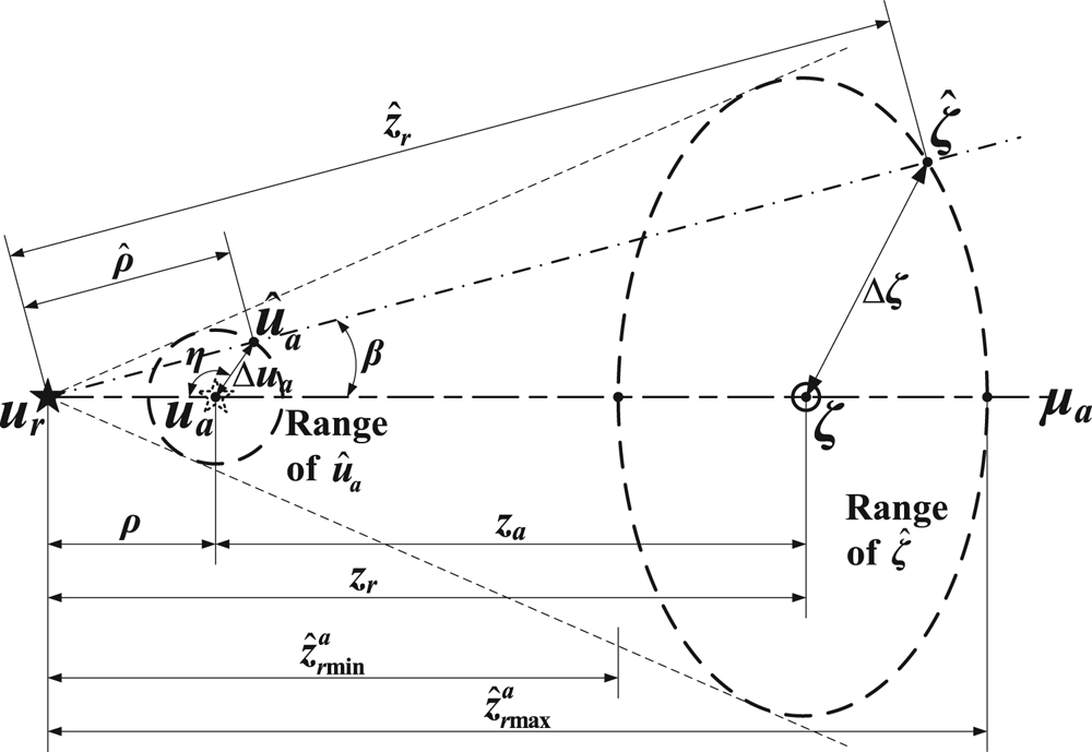
When ur is identified, through the atmospheric refraction model, the estimated zenith direction $\hat{\boldsymbol{\zeta }}$ is determined by the estimated stellar apparent direction ${\hat{\boldsymbol{u}}_{\boldsymbol{a}}}$
 with the error Δua which is affected by attitude accuracy, as shown in Figure 2.
Geometric relationship of error ranges projected onto the celestial sphere

The spherical triangles satisfy


where

Particularly in μa direction, the estimated real zenith distance $\hat{z}_r^a$ satisfies

Thus


This indicates that the zenith error range shrinks with increasing ρ (equivalent to za or zr). The whole result will be given in Section 5.1.
For the purpose of calculating the zenith direction, the stellar azimuth coordinate system (denoted as frame a) is established, with the X a axis oriented to the stellar real direction and Y a axis upward in plane μa, as shown in Figure 1. Obviously,

The vector-matrices V and W are established as


Hence, the orthogonalised coordinate conversion matrix $\boldsymbol{C}_{\rm a}^{\rm b}$ is


where C0 is the non-orthogonal matrix.
λb and φb are the longitude and latitude coordinates of zenith direction in frame b, which satisfy

Through calculating the real-time Greenwich hour angle of Aries A ϒ, the conversion matrix $\boldsymbol{C}_{\rm i}^{\rm e}$ from frame i to geocentric equatorial rotating coordinate system (denoted as frame e) can be obtained. Therefore, the geographical longitude λ and latitude φ can be solved by

Assigning the east-north-zenith (E-N-U) coordinate system (denoted as frame n) as the navigation coordinate system, the conversion matrix $\boldsymbol{C}_{\rm n}^{\rm e}$ can be calculated through the two Euler angles −(90° − φ) and −(90° + λ) in a rotation order of 1-3. Thus the conversion matrix $\boldsymbol{C}_{\rm n}^{\rm b}$
 can be deduced by $\boldsymbol{C}_{\rm i}^{\rm b}$
 , $\boldsymbol{C}_{\rm i}^{\rm e}$
 and $\boldsymbol{C}_{\rm n}^{\rm e}$
 , with three Euler angles named respectively as yaw angle -ψ, pitch angle θ and roll angle ϕ in a rotation order of 3-1-2. ψ, θ and ϕ are assigned as the relative attitude angles of the aircraft.
The analysis above presents the relation between the position and attitude parameters of the UAV. However, neither the precise attitude nor position information can be directly measured by CNS alone in refractive conditions. High accuracy attitude and position determinations are key problems. In Sections 3 and 4, these will be further discussed.
3. Research on triple-FOV star sensors navigation by stellar refraction
Generally, for spacecraft, if the observed stars are successfully identified by image matching algorithm, then attitude with high accuracy can be ensured by high-precision star sensor and optimised attitude determination method. However, for aircraft, the atmosphere will absorb, scatter and refract the starlight. This may seriously decrease the light intensity and increase background noise, making starlight harder to detect, especially in daytime. As a result, both the star pattern recognition and attitude determination accuracy will be affected.
To solve these problems, the narrow FOV star sensor has been developed to improve the sensitivity of CCD (Charge Coupled Device) arrays by sacrificing the detection range. Thus, the application of multiple-FOV star sensors is necessary to ensure both the observability and the precision (Wu et al., Reference Wu, Wang and Wang2015, Reference Wu, Xu, Wang, Lyu and Li2019). On this basis, we can extract the refractive images from combined star map and increase the matching tolerance to maintain the recognition rate. This can be much easier or even unnecessary when sensors are working in tracking mode (Li et al., Reference Li, Sun and Zhang2015; Wang et al., Reference Wang, Zhu, Qin, Zhang and Li2017a).
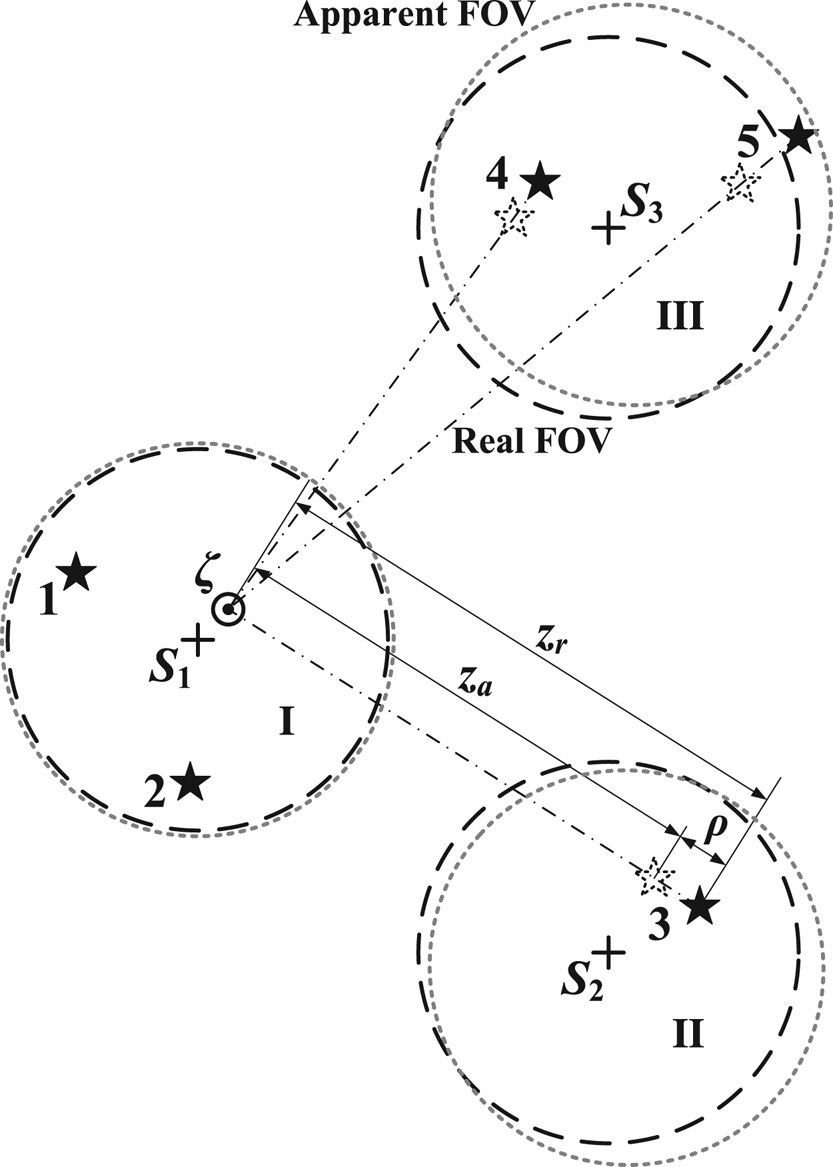
The identified stars in combined FOV are shown in Figure 3, where Sj (j = 1, 2, 3) are boresight projections on the celestial sphere corresponding to star sensor I, II or III. For each observed star, the projections of ual, url and ζ are on the arc where the celestial sphere meets with μal (l = 1, 2, 3…).
Geometric relationship of multiple FOVs and stars projected onto the celestial sphere

Obviously, ζ is the common intersecting line of all the stellar azimuth planes. When the precise ζ is calculated, the position can be acquired. However, according to Section 2, calculations of the zenith direction and attitude are coupled. So the following two schemes are designed to seek the efficient method.
3.1 Coplanar distribution scheme
When a UAV is cruising straight and level, the Z b axis can be considered as orienting to the zenith. That means that, if the observed starlight orientation is close to the Z b axis (Star 1 and 2 in Sensor I), then ρ will be very small, i.e.,

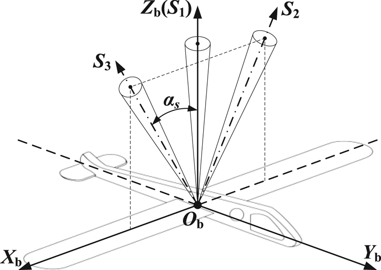
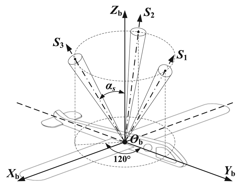
Therefore the absolute attitude of the vehicle can be directly determined by at least two identified stars in theory (Shuster and Oh, Reference Shuster and Oh1981; Zhu et al., Reference Zhu, Ma, Cheng and Zhou2017). Based on this, a coplanar distribution scheme by three star sensors is designed to analyse the problem, as shown in Figure 4, where αs (0 ≤ αs ≤ 90°) is marked as the strapdown installation angle.
Installation of the coplanar distribution scheme

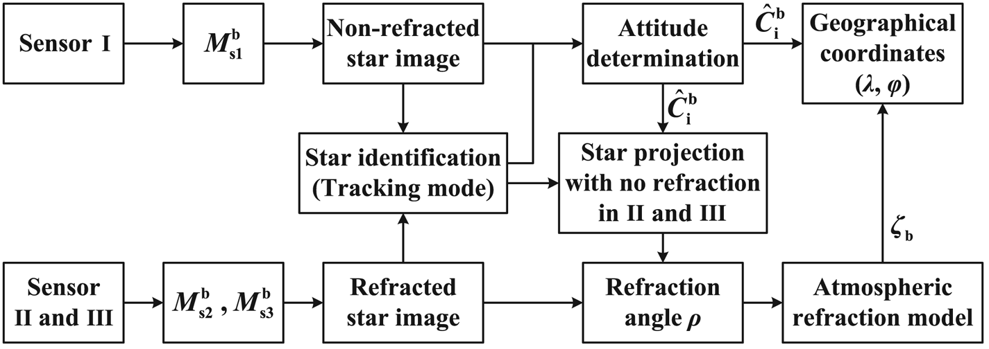
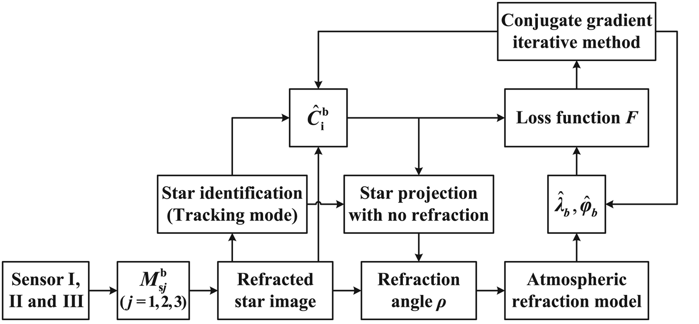
Sensor I is used to measure the ‘non-refracted’ stars and estimate the attitude, whereas Sensors II and III, in a symmetrical distribution, are utilised to observe the refracted stars and calculate the geographical coordinates by the atmospheric refraction model with $\hat{\boldsymbol{C}}_{\rm i}^{\rm b}$ provided by Sensor I. Furthermore, sensors on both sides can increase the observation scope and ensure the FOVs do not scan blind areas (e.g. the sun and the moon) simultaneously. The flowchart is presented in Figure 5.
Flowchart of the coplanar distribution scheme

However, this scheme has two disadvantages. First, limited by the FOV of Sensor I, the detection probability is low and the angular distance between different starlight vectors is rather small, which may lead to big errors in attitude. Second, when the aircraft manoeuvres in flight, boresight of Sensor I will deviate from the zenith direction and refraction cannot be ignored. Therefore, general cases should be studied.
3.2 Triangular distribution scheme
The universality of triple-FOV star sensors in triangular distribution can enhance the practicability of CNS. These are installed, as shown in Figure 6, to satisfy the omnibearing observation.
Installation of the triangular distribution scheme

Through derivation of the Jacobi identity (see Appendix part in details),

Based on this, the loss function (Wang et al., Reference Wang, Gao and Wang2021a) is established as

where n is the total number of observed stars, al (l = 1,…,n) are a set of nonnegative weights satisfying

Obviously, the less estimated errors of $\hat{\boldsymbol{C}}_{\rm i}^{\rm b}$ and ${\hat{\boldsymbol{\zeta }}_{\rm b}}$
 are, the smaller function value is. Combined with Equation (22), variables of the loss function are converted into two scalars (λb and φb) and one matrix, which cannot be solved by existing classical methods on account of strong nonlinearity. Now we try to establish a conjugate gradient iterative algorithm to testify the improvement of navigation accuracy by reducing the loss function value.
Actual observed stars are measured in the combined FOV of I, II and III, so a rough attitude $\hat{\boldsymbol{C}}_{\rm i}^{\rm b}$ can be estimated without refraction compensation, thereby obtaining ${\hat{\lambda }_b}$
 and ${\hat{\varphi }_b}$
 in a similar way. Regarding $\hat{\boldsymbol{C}}_{\rm i}^{\rm b}$
 as a constant matrix in each iteration, the loss function can be processed by conjugate gradient iterative method to update attitude and position information, as shown in Figure 7 (Rivaie et al., Reference Rivaie, Mamat and Abashar2015; Liu et al., Reference Liu, Feng and Zou2018).
Flowchart of the triangular distribution scheme

The gradient function satisfies


Therefore, the conjugate gradient iterative method contains the following steps:
Step 1: When ‖gk‖ ≤ ε (k = 0, 1, 2…, ε is the specified precision), iteration algorithm stops.
Step 2: Determine the iteration step length αk by Armijo line search method (Nocedal and Wright, Reference Nocedal and Wright2006). Then,

where the initial search direction d0 = −g0.
Step 3: Revise the refracted starlight by ${({\hat{\lambda }_b},{\hat{\varphi }_b})_{k + 1}}$ through atmospheric refraction model and update the attitude $\hat{\boldsymbol{C}}_{\rm i}^{\rm b}$
 .
Step 4: Compute Fk + 1 and gk + 1 by $\hat{\boldsymbol{C}}_{\rm i}^{\rm b}$ and ${({\hat{\lambda }_b},{\hat{\varphi }_b})_{k + 1}}$
 .
Step 5: Compute βk + 1 by

Step 6: Compute dk + 1 by

Step 7: Set k := k + 1, go to step 1.
The authors expected to obtain an accurate result by the gradient iterative algorithm above. However, the iteration cannot efficiently converge to the given nominal condition, when ignoring the influence of attitude on gradient. Its uncertainty will be demonstrated in Section 5.2.
Indeed, the common principle of the double schemes above is to correct the position through a rough attitude provided by CNS. It can be easily verified that the tiny attitude error will be amplified by the atmospheric refraction model and then seriously affect the positon accuracy. If an initial location can be given, through the reverse process, a precise attitude will be acquired. Maybe SINS can do this.
4. SIMU/triple star sensors deep integrated method in refractive effect
The traditional INS/CNS deep integrated method without refraction correction can be designed as in Figure 8. In the INS section, specific forces fE, fN, fU along the three axes can be calculated through $\boldsymbol{\omega }_{{\rm ib}}^{\rm b}$ provided by gyroscope and $\boldsymbol{\alpha }_{{\rm ib}}^{\rm b}$
 provided by accelerometer. On the basis of dynamic relationship, position parameters $\hat{\varphi }$
 , $\hat{\lambda }$
 , $\hat{h}$
 and attitude parameters $\hat{\theta }$
 , $\hat{\phi }$
 , $\hat{\psi }$
 can be acquired, thus obtaining ${\hat{\boldsymbol{\zeta }}_{\rm b}}$
 (fused with initial location and horizontal reference) and matrix of misalignment angle MS. Owing to the non-damping and instability in altitude channel of INS (Qin, Reference Qin2006), as well as the non-observability of altitude in CNS, the nominal altitude hr will be directly given by altimeter in this paper.
Flowchart of SIMU/triple star sensors deep integrated without refraction correction

In the CNS section, to ensure high-precision navigation in long-endurance flight, three (or two at least) FOVs should be available to detect stars, whose numbers of observed stars are N 1, N 2 and N 3. Thus, the identified url and the measured val can determine $\hat{\boldsymbol{C}}_{\rm i}^{\rm b}$ then calculate position parameters φ, λ and attitude parameters θ, ϕ, ψ through ${\hat{\boldsymbol{\zeta }}_{\rm b}}$
 provided by INS.
Now, the new deep integrated method with refraction correction is shown as Figure 9.
Flowchart of SIMU/triple star sensors deep integrated with refraction correction

Based on the atmospheric refraction model, $\hat{\boldsymbol{C}}_{\rm i}^{\rm b}$ determined by the identified url and the corrected ${\hat{\boldsymbol{v}}_{\boldsymbol{r}l}}$
 is more precise. The updated vrl (calculated by $\hat{\boldsymbol{C}}_{\rm i}^{\rm b}$
 and url) and the measured val can then determine the corrected ζbl of each observed star. Calculate ${\bar{\boldsymbol{\zeta }}_{\rm b}}$
 as

thus obtaining $\bar{\varphi }$ , $\bar{\lambda }$
 (i.e., φ, λ) followed with θ, ϕ, ψ.
Kalman filter is utilised to realise the data fusion (Pan et al., Reference Pan, Cheng, Liang, Yang and Wang2013). The navigation deviations are denoted as

So the misalignment angles ${{\varPhi_x}}, {{\varPhi_y}}, {{\varPhi_z}}$ can be determined by (Zhu et al., Reference Zhu, Wang, Li, Che and Li2018)

According to the error equations of SINS, build the 15-dimensional state model as follows

where δvE, δvN, δvU are velocity deviations; εx, εy, εz are gyroscope drifts; ∇x, ∇y, ∇z are accelerometer biases. The state equation is


where ωεx, ωεy, ωεz are gyroscope noises; ω ∇x, ω ∇y, ω ∇z are accelerometer noises. Non-zero elements of FN are (Qin, Reference Qin2006; Li et al., Reference Li, Sheng, Zhang, Wu, Xu, Liu and Zhang2018)

where RM is the main radius of curvature of the meridian; RN is the main radius of curvature of prime vertical; ωie is the rotational angular velocity of the Earth.

Build the six-dimensional measurement model as follows

The measurement equation is


where Vm is measuring noise.
Generally, the data output rate of the SIMU is higher than the star sensor. During the interval of CNS output, INS alone calculates and updates the navigation parameters and matrix P in Kalman filter. Otherwise, data fusion proceeds and the final filtering result X will be feedback to INS and compensate for the state errors. Then X will be reset to zero until the next filtering moment.
5. Simulation verification and analysis
In this section, simulation of the zenith error range located by different zenith distances will be given first. Then, both the static simulations of CNS with the coplanar distribution scheme (assigned as Scheme 1) and the triangular distribution scheme (assigned as Scheme 2), as well as the dynamic simulations of SINS/CNS deep integrated with Scheme 2, will be discussed.
5.1 Simulation of the zenith error range
According to Figure 2, assign μa as the celestial equator, ur orienting to the vernal equinox, $({\hat{\alpha }_\zeta },{\hat{\delta }_\zeta })$ as the right ascension and declination of $\hat{\boldsymbol{\zeta }}$
 , then ζ(zr, 0). Obviously,

Therefore, combined with Equation (12),

Setting Δua = 1′′, h = 15 km, then the zenith error ranges in various conditions are shown in Figure 10.
Zenith error ranges with different zenith distances

It can be seen that both the error range and Δζ max decrease with increasing zenith distance. However, even if Δζ is about 25′ (e.g. za = 80°, Δζ max = 25⋅3′), the position error will be up to 46 km (one arc minute gives an error in coordinates of approximately one nautical mile, i.e., 1.852 km) on the Earth's surface, let alone the larger Δua in actual flight.
It should be noted that refraction effects in the vicinity of the horizon are more complicated (Yu et al., Reference Yu, Cao, Tang, Luo and Zhao2015). Therefore, the optimal navigation star for positioning should be located high enough above the horizon.
5.2 Static simulation of CNS
In static simulations without any measurement noise, the Monte Carlo method with 200 times independent repeated experiments will be used to calculate the root mean square error (RMSE) of navigation parameters. Setting h = 15 km, αs = 70°, corresponding αA = 1⋅009 (The Purple Mountain Observatory, 2021), $\boldsymbol{C}_{\rm i}^{\rm e}$ = I3×3.
5.2.1 Precision analysis with Scheme 1
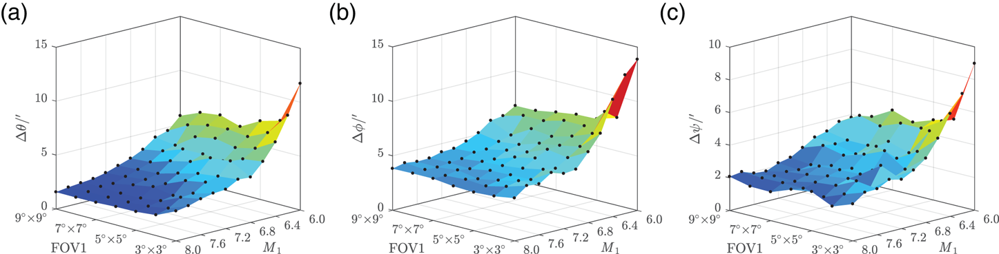
On the condition that the Z b axis orients to the zenith, λ, φ and ψ are randomly generated. According to Fan and Li's study (Reference Fan and Li2011), the initial limiting magnitude (denoted as M) of star sensors I, II and III was set as 8⋅0, with FOV 3° × 3°. Then, the FOV of Sensor I was changed from 3° × 3° to 9° × 9°, and M 1 from 8⋅0 to 6⋅0. Sensors II and III remain unchanged. The simulation results are shown in Figures 11–13.
Absolute attitude RMSE: (a) right ascension error (b) declination error (c) roll error

Position RMSE: (a) longitude error (b) latitude error (c) total position error

Relative attitude RMSE: (a) pitch error (b) roll error (c) yaw error

Obviously, with the decrease of M 1 and FOV1, which indicate fewer stars being detected, both the attitude error and position error tend to increase. Besides, as shown in Figure 10, ρ < 4⋅2′′ when za < 10°, h = 15 km. Although the absolute attitude RMSE is strictly limited within 1′′, the position RMSE and relative attitude RMSE, however, are still big enough especially for positioning, let alone with manoeuvre or measurement noise in calculation. This indicates that Scheme 1 has low engineering feasibility.
5.2.2 Precision and loss function analyses with Scheme 2
Sensors I, II and III with FOV 3° × 3° are equivalent. Mj (j = 1, 2, 3) is reduced from 8⋅0 to 6⋅0. The observation results are shown in Figure 14 where the success ratio of attitude determination is the percentage that at least two stars can be observed in 200 samples. It can be seen that both the number of observed stars and the success ratio decrease with reducing M. Ensuring the detectivity of each star sensor is vitally important in actual flight. Therefore, ${M_j} \ge 6.4,{\bar{N}_j} > 1$ (j = 1, 2, 3) with success ratio higher than 90% should be satisfied in practice to ensure real-time accuracy, as set out in Section 5.3.
Mean number of observed stars and success ratio of attitude determination

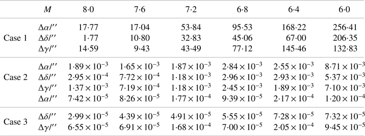
For each sample where attitude was successfully determined, the attitude determination method without refraction corrected is assigned as Case 1, the method with only two FOVs available with refraction corrected is assigned as Case 2 and the method with all three FOVs available with refraction corrected as Case 3. Thereinto, the nominal location is given in Case 2 and Case 3. The simulation results of the absolute attitude error are shown in Figure 15 and Table 1.
Attitude RMSE in the three cases

Attitude RMSE in the three cases

Obviously, the attitude precision determined by Case 1 is rough. Case 2 is worse than Case 3, despite its computational attitude RMSE with finite bit capacity of the processor in algorithm simulation having already been equal to zero under the ideal conditions. In the long-endurance flight condition, Case 2 can be considered as an alternative.
The next step is to verify the feasibility of the conjugate gradient iterative method mentioned in Section 3.2. Set M = 8⋅0. Assign λb 0 = 151⋅22° and φb 0 = 85⋅39°, solved by a random flight status as the nominal location. Then, separately plot the loss function in the domain around (λb 0, φb 0) with attitudes determined by Case 1 and Case 3, as in Figure 16, where al = 1/(N 1 + N 2 + N 3) (l = 1,…, N 1 + N 2 + N 3). It can be seen that the loss function is non-convex when the rough attitude (Case 1) is given. Only if the precise attitude (Case 3) is acquired can $({\hat{\lambda }_b},{\hat{\varphi }_b})$ converge to (λb 0, φb 0) with loss function minimised. However, this is difficult to realise in application with refraction influence.
Loss function simulation: (a) attitude determined by Case 1, (b) attitude determined by Case 3

5.3 Dynamic simulation of SINS/CNS
5.3.1 Environment settings
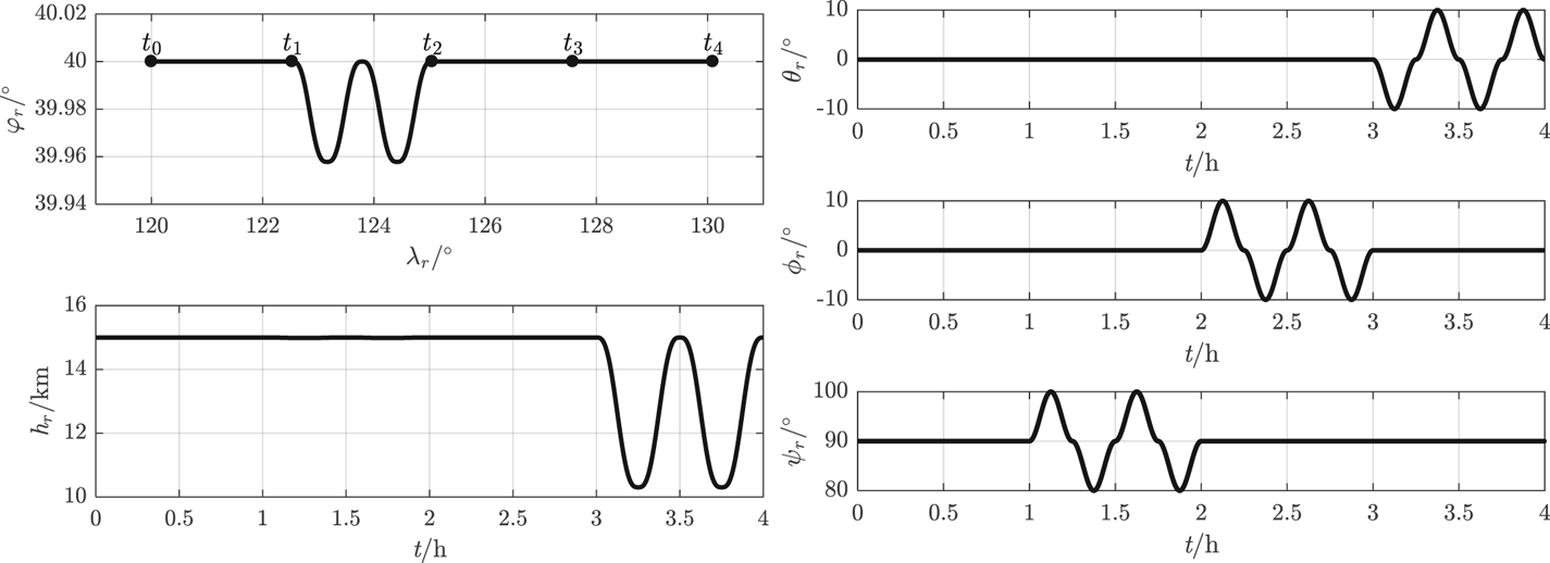
A simplified nominal flight trajectory with manoeuvring in the stratosphere is designed to verify the integrated method. One flight cycle is set at 4 h with time nodes t 0, t 1, t 2, t 3, t 4 at intervals of 1 h. The UAV's velocity is set at 60 m/s constantly orienting to the Y b axis (attack angle is 0°, sideslip angle is 0°) and the initial real (nominal) kinematic parameters satisfy (φr(t 0), λr(t 0)) = (40°, 120°), hr(t 0) = 15 km, θr(t 0) = ϕr(t 0) = 0°, ψr(t 0) = 90°. The initial Greenwich hour angle of the vernal equinox A ϒ(t 0) = 59⋅03°. The designed kinematic parameters vary as shown in Figure 17.
Real kinematic parameters of UAV

The simulation parameters of various navigational apparatus are shown in Table 2. In addition, αs = 70°, αA = 1⋅009, FOV 3° × 3° and δvE ,N,U(t 0) = 0⋅1 m/s, $\varPhi$ x ,y,z(t 0) = 1′′, δφ(t 0) = δλ(t 0) = 1′′, δh(t 0) = 50 m.
Simulation parameters of navigational apparatus

5.3.2 Flight simulation within 4 h
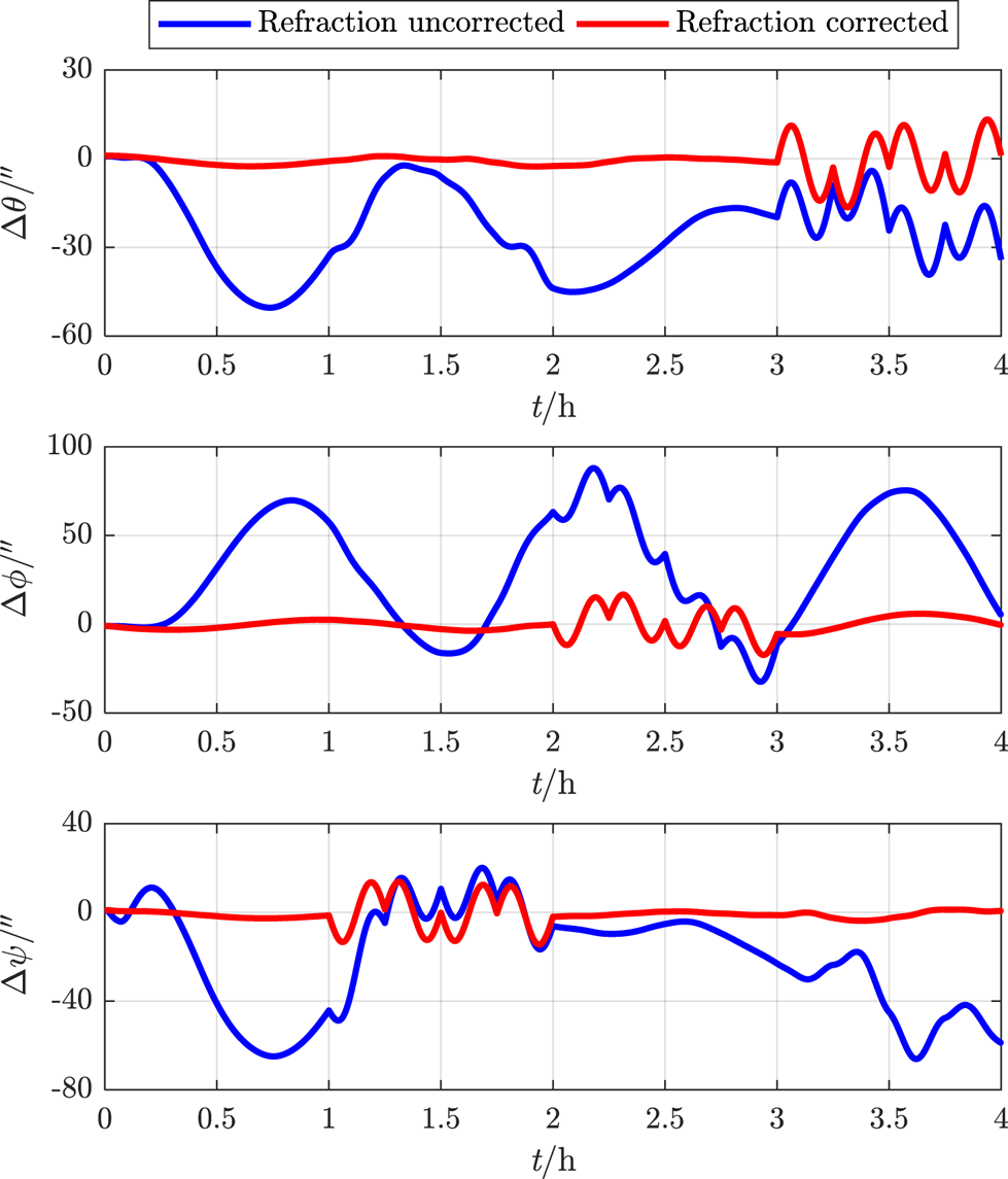
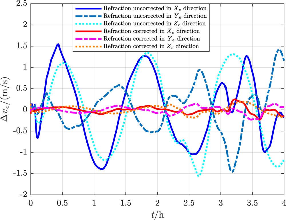
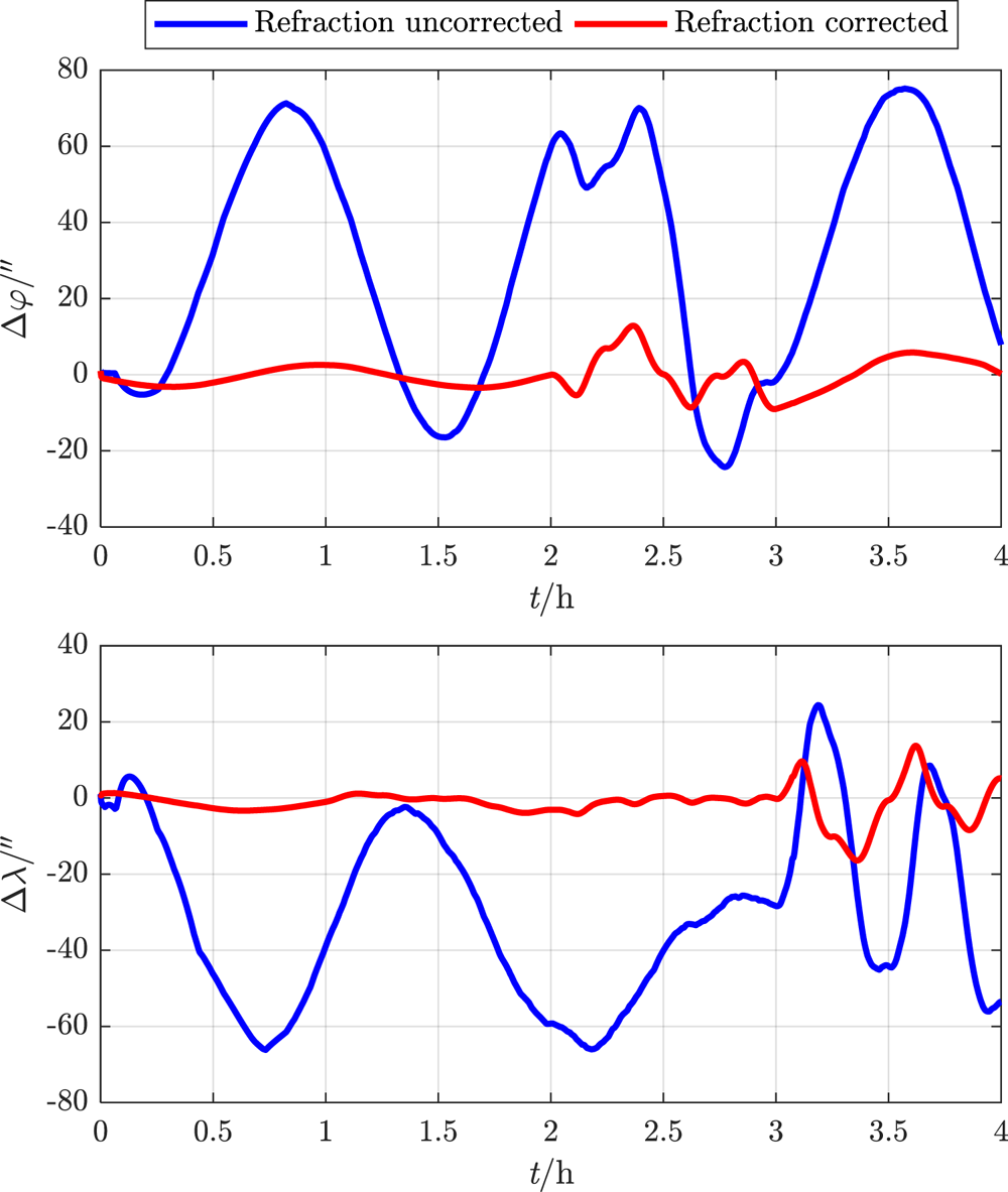
In one 4 h flight cycle, the constant M = 8⋅0. For the proposed deep integrated method with refraction corrected and the traditional method with refraction uncorrected, the real-time simulation errors of navigation parameters are estimated as shown in Figures 18–21. The RMSEs of the navigation parameters are shown in Table 3.
Attitude error within 4 h

Velocity error within 4 h

Geographical coordinate error within 4 h

Total position error within 4 h

Navigation parameter RMSE of 4 h flight

It can be seen that, under the influence of atmospheric refraction, all the navigation error data of the traditional integrated method without correction oscillate or even diverge, while the proposed deep integrated method with correction can eliminate the influence of tight coupling between attitude and position on navigation accuracy, and thus effectively restrain navigation error within a limited range even in manoeuvring flight.
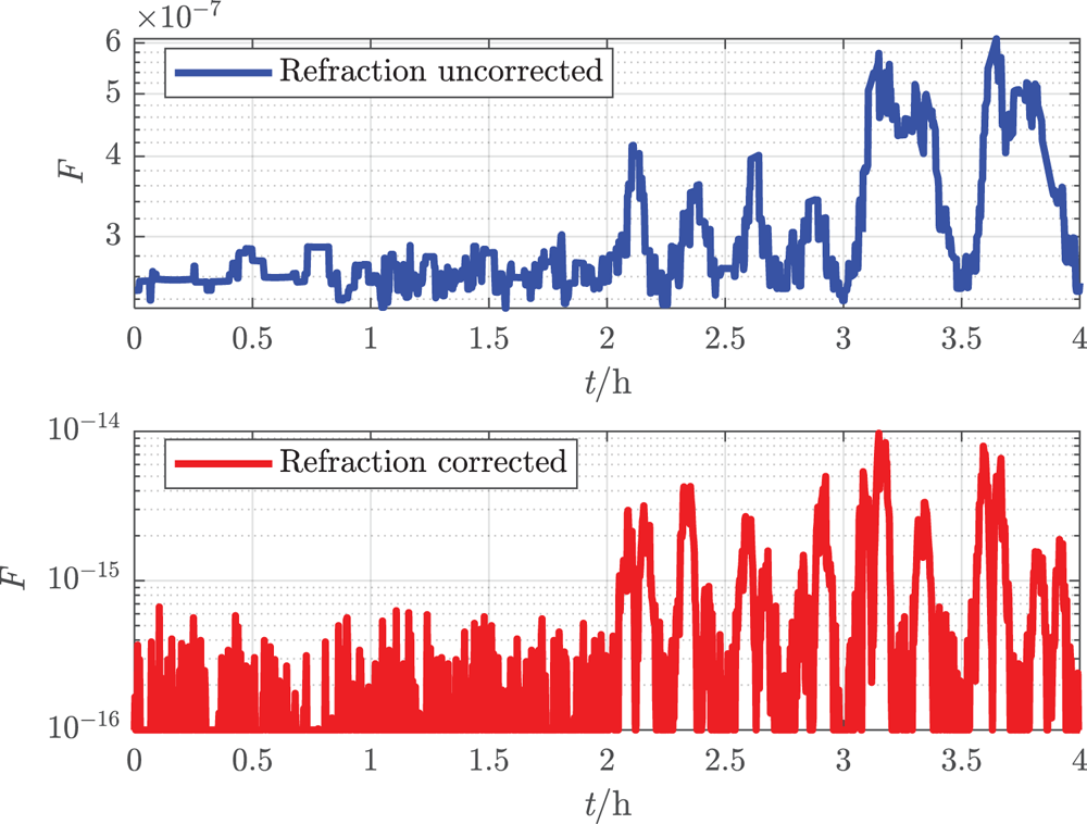
The real-time loss functions of the two methods are plotted in Figure 22. Although the orders of magnitude are so small that the numerical value may overflow in calculation, it does verify that smaller function value indicates higher navigation accuracy.
Loss function within 4 h

5.3.3 Flight simulation within 24 h
For the purpose of simulating the decrease of limiting magnitude with enhancing atmospheric background radiation in long-endurance flight, M is respectively set to 8⋅0, 7⋅7, 7⋅4, 7⋅1, 6⋅8 and 6⋅5 in six continuous flight cycles (i.e., 24 h flight). The final results of the proposed deep integrated method are shown in Figure 23.
Navigation error and mean number of observed stars within 24 h

It can be seen that, with the decrease of limiting magnitude together with the number of observed stars among different flight cycles, the navigation accuracy tends to be worse. Nevertheless, the position RMSE in each hour can still be restrained within 1⋅5 km and the attitude real-time error can be restrained within 70′′ even after 24 h manoeuvring flight with limiting magnitude above 6⋅5. Obviously, the proposed method can overcome the problem of unreliability of CNS operating by itself. When better conditions are satisfied, e.g., all the sensors are available to detect stars all the time, higher navigation accuracy can be achieved, and thus the cruising ability of the UAV can be ensured.
6 Conclusions
(1) Based on the atmospheric refraction model, the introduction of a stellar azimuth coordinate system can help to effectively establish the coupling relationship between attitude parameters and position parameters.
(2) Based on the geometric relationship whereby all the stellar azimuth planes intersect on the common zenith direction, the proposed loss function can be utilised to evaluate the navigation accuracy. This can be also applicable to further intelligent navigation algorithms.
(3) The observed refracted starlight with wider zenith distance contributes to precise positioning, while the observed refracted starlight with narrower zenith distance contributes to precise attitude determination. Therefore, the strapdown installation of triple-FOV CNS must comprehensively coordinate the position accuracy, attitude accuracy, application range of atmospheric refraction model and the manoeuvring flight strategy according to the engineering requirements.
(4) CNS alone cannot ensure sufficient position accuracy by a rough attitude with refraction influence, which is unacceptable for an aerial vehicle.
(5) The SIMU/triple star sensors deep integrated method can correct the attitude error through the atmospheric refraction model as well as a rough location and horizontal reference provided by SINS, acquiring a more accurate position. Based on the high-precision daytime star sensors with strong detectivity, this method can ensure navigation accuracy by Kalman filter even for all-day flight, which can be applicable to a HALE UAV in steady-state cruise in the stratosphere.
Refractivity in the stratosphere is weaker than at sea level, so the precise refraction model and horizontal reference are strictly demanded. When adjusting the refraction model for some specific complex circumstances, the methodology proposed in this paper also applies. In addition, the acquisition of precise altitude information and the evasion of the sun or the moon should be seriously considered in engineering applications.
Acknowledgements
This research is supported by the Defense Industrial Technology Development Program under research grant JCKY2018601B101, which is greatly appreciated.
Appendix
For Equation (25), according to the Jacobi identity in elliptic function theory, assign

Therefore,

As va, vr and ζb are unit vectors, thus


Therefore,

As va, vr and ζb are coplanar, thus