I. INTRODUCTION
Thixoforming is a near-net-shape manufacturing process that is performed at temperatures between the solidus and the liquidus, Reference Campo, Proni and Zoqui1–Reference Chen, Chen, Wang and Du3 providing different recrystallization behavior as compared to conventional processes. Reference Chen, Wang, Gao, Fu and Li4–Reference Ai, Li, Zhang, Liu, Ma, Pei and Gong8 The most distinct characteristic of thixoformed microstructure is the co-existence of liquid and solid during processing (since this occurs at semi-solid temperatures), and the formation of a primary phase with near-spherical grain morphology. Reference Du, Zhu, Li and Zhang9–Reference Chen, Chen, Han, Hu, Han, Zhao, Xia and Wan11 This process has received considerable attention recently due to its significant advantages over traditional metal forming process, such as minimization of as-cast porosity and macro-segregation; reduced forming temperatures, forming forces, and machining costs; and high strength and corrosion resistance. Reference Wang, Lu and Yu12–Reference Wang, Shang, Lu and Yu15
During the thixoforming process, the billet feedstock is reheated into the semisolid state before the forming operation. It is well known that semisolid alloys have a thixotropic behavior in which the fluidity is time-dependent and strongly shear-thinning, meaning that at rest the material can be handled like a solid, and during shearing it becomes very fluid with liquid-like flow. Reference Zabler, Ershov, Rack, Garcia-Moreno, Baumbach and Banhart16,Reference Brabazon, Browne and Carr17 This behavior greatly relies on nondendritic and spherical/globular microstructure being achieved during the feedstock preparation process. Reference Campo, Proni and Zoqui1–Reference Wang, Phillion and Lu23 Tzimas and Zavaliangos Reference Tzimas and Zavaliangos18 reported that the geometry of the solid grains plays an important role in determining the flow response of the material during thixoforming, while Meng et al. Reference Meng, Sugiyama and Yanagimoto19–Reference Zhu and Sohn21 showed that the mechanical behavior of a material during semisolid forming is strongly affected by the morphology of the microstructure. Moradi et al. Reference Moradi, Nili-Ahmadabadi, Poorganji, Heidarian and Furuhara22 also demonstrated that the finer and globular-shape particles obtained from reheating process is the major factor for the success of thixoforming. Thus, precise control of the reheating stage is very important, to create semisolid material with a specified fraction solid, and with fine and uniform globular microstructure.
At present, although much of the new research and application of thixoforming is focused on wrought metallic alloy developments, Reference Wang, Phillion and Lu23–Reference Chen, Chen, Qin and Du25 most commercial thixoforming is performed using conventional aluminum-based casting alloys owing to their high fluidity and good ‘castability’. Specifically, there is great interest in using Al–Si alloys as a material for thixoforming due to the fact that Al–Si alloys have a relatively wide solid–liquid temperature interval and high fluidity in the semisolid region. Reference Birol26 These properties help to achieve good quality thixoformed components. In this work, a novel two-stage reheating process, recently proposed by Wang et al. Reference Wang, Brabazon, Phillion and Lu27 for AA6061, is explored for application to Al–Si casting alloys. Please note that the idea of two-stage reheating process is the same as in AA6061, but the actual method used for wrought and casting alloys are different. The first-stage of the reheating process for wrought alloys is a reheat to the solidus temperature, while for casting aluminum alloys, the liquidus temperature is used as the starting point. Based on the conventional Al–Si casting alloy, 356.0, composition and process design were tailored to enable the development of a high-strength aluminum casting alloy with superior characteristics for thixoforming. The coarsening rate constant, fraction of entrapped liquid, grain size and shape are evaluated under various processing conditions and reported for both the two-stage and the traditional feedstock reheating processes to compare the differences in microstructure obtained using each method.
II. EXPERIMENTAL PROCEDURES
A. Alloy development
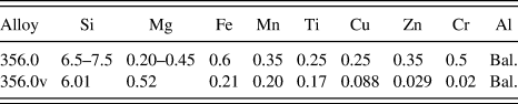
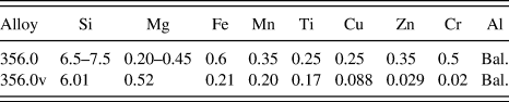
The material investigated in this work was a variant of the common commercial 356.0 Al–Si casting alloy, with a chemical composition as given in Table I. This new alloy, denoted 356.0v has a lower Si content (6.01 versus 6.5–7.5 wt%) and a higher Mg content (0.52 versus 0.20–0.45, wt%) as compared to 356.0, and was developed specifically for thixoforming. Except for Si and Mg, the chemical composition of 356.0v falls within the standard range found in the ASM Handbook. Reference Kearney28 The modification of the Si and Mg was developed to improve thixoformability of casting Al–Si casting alloys whilst also approaching the performance of wrought alloys. The specific content of Si and Mg in 356.0v was determined according to the thermodynamic and phase equilibriums method. Reference Liu, Atkinson and Jones29 First of all, a slight decrease in Si content was applied to enlarge the solidus–liquidus interval, to facilitate semisolid processing. The additional Mg was added to assist in forming additional Mg2Si, which will improve the macroscopic mechanical properties. Further, additional Mg will result in a primary-phase grain refinement. Reference Abedi, Shahmiri, Esgandari and Nami30 Salleh et al. Reference Salleh, Omar and Syarif31 indicated that the fracture behavior of the thixoformed alloys was improved after a T6 heat treatment, with significantly higher ductility.
Chemical compositions (wt%) of 356.0 alloy in ASM Handbook and developed 356.0v alloy measured with a PMI-MASTER PRO.
Bal. = Balance
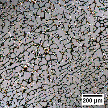
The initial microstructure of the developed 356.0v alloy, obtained from vertical electromagnetic continuous casting billets 70 mm in diameter, is shown in Fig. 1. As can be seen, this microstructure consists of fine dendritic grains with a few bright phases of blocky Si precipitates distributed at the grain boundaries. This blocky Si phase will re-melt once the material heated to a temperature above the eutectic point. Assuming that thixoforming eliminates the blocky Si, these precipitate will not cause embitterment Reference Shankar, Riddle and Makhlouf32 during usage. After casting, samples 15 ×15 × 15 mm3 were machined from the billet for the reheating experiments.
Initial dendritic microstructure of the 356.0v casting alloy obtained by vertical electromagnetic continuous casting.

B. Thermal analysis
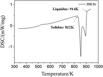
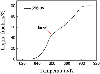
The process of thixoforming requires a solidus–liquidus interval that is wide enough to facilitate the formation of spherical solid grain. According to the Al–Si phase diagram, a reduction in the Si content from 7 to 6 wt% will significantly increase the solidus–liquidus interval. To accurately determine the evolution in fraction solid with temperature for 356.0v, along with the solidus and liquidus temperatures, differential scanning calorimetry (DSC) was performed using a NETZSCH STA 449 F3 thermal analysis system (Netzsch Group, Selb, Germany). The heat flow signal obtained via DSC during cooling of a small sample is shown in Fig. 2. As can be seen, the solidus and liquidus temperatures of 356.0v are 812 and 914 K, respectively. Thus, the solidus–liquidus temperature range for 356.0v is nearly 70% larger as compared to 356.0 (888 and 828 K (Ref. Reference Kearney28)). The corresponding evolution of liquid fraction calculated from the DSC heat flow data by integration is given in Fig. 3. As can be seen, the slope of the curve is quite high at temperatures above 840 K because this alloy, like 356.0, contains a significant fraction of eutectic.
Differential thermal analysis curve of 356.0v during heating process at a rate of 10 K/min.

Change in liquid fraction with temperature of 356.0v casting alloy derived from the recorded DSC curve at a heating rate of 10 K/min.

C. Two-stage reheating process
A muffle furnace (Fisher Scientific 550-126, ThermoFisher Scientific, Johnston, Iowa) was used to reheat the sample to the semisolid region during the reheating process, with an average heating rate of 10 K/min. As discussed in previous research, Reference Wang, Brabazon, Phillion and Lu27 the advantage of using a two-stage reheating process when preparing feedstock for thixoforming is to create microstructure that has both a continuous solid skeleton for handling purposes and provides thixotropic behavior during thixoforming. Based on the results shown in Fig. 3, it is also noticed that the amount of eutectic represents the position of the ‘knee’ existing for fraction liquid versus temperature curve. The existence of a knee at around liquid fraction of 0.5 gives controllability in the thixoforming process. Reference Liu, Atkinson and Jones29 This knee of 356.0v casting alloy is located near a fraction liquid of 0.5, corresponding to the start of the nonequilibrium eutectic melting point. In effect, it acts as a ‘brake’ on the liquid formation, which makes the 356.0v casting alloy so suitable for thixoforming.
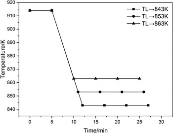
A comprehensive investigation was then undertaken to compare the microstructure obtained from both the traditional reheating process for thixoforming, and the proposed two-stage method. For the traditional reheating process, the samples were directly reheated to 843, 853, and 863 K in the muffle furnace, and then quenched after holding times of 15, 20, and 25 min. This corresponds to (see Fig. 3), liquid fractions of 0.1, 0.3, and 0.5, respectively. For the two-stage reheating process, an initial study for casting aluminium alloy was carried out on six different heating routes near the solidus and the liquidus temperatures following Reference Wang, Brabazon, Phillion and Lu27 to determine the optimum intermediate time /temperature combination. Based on this initial study, the use of the liquidus as the intermediate temperature and a 5 min intermediate reheating time was optimal for promoting the desired microstructure for thixoforming), the billets were first reheated to the liquidus temperature for 5 min (corresponding to stage 1), then cooled to 843, 853, and 863 K over a 5-min cooling period, and finally held at temperature for 5, 10, and 15 min, respectively (corresponding to stage 2). A schematic of the process route is depicted in Fig. 4. Please note that when the sample was reheated to liquidus temperature during the first stage, the semisolid billets still held its own weigh thus its initial solid cubic shape could be maintained as a result of the reasonable controlling of holding temperature. All samples after reheating process were then rapidly quenched in cold water to freeze the semisolid microstructures for optical microscopy. The quenched specimens were grounded, polished, and then etched with the mixed acid solution of 2 mL HF, 3 mL HCl, 5 mL HNO3, and 190 mL H2O. The optical microstructures were observed by an inverted microscope, Axio Observer A1m (Carl Zeiss, Jena, Germany).
Reheating temperatures versus times used for investigation of the two-step reheating process for Al–Si casting alloy.

D. Data analysis
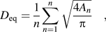
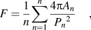
Optical micrographs of each specimen were obtained using an Axio Observer A1m. The resulting microstructures were then analyzed using image analysis methods. The grain diameter, roundness, and the amount of liquid trapped within the solid phase were evaluated using Image Pro Plus (IPP) analysis software. The average grain size and grain shape were described by equivalent diameter (D eq) and roundness (F) of solid grains, which were respectively defined by following relationships. Reference Chen, Chen, Wang and Du3
 $${D_{{\rm{eq}}}} = {1 \over n}\sum\limits_{n = 1}^n {\sqrt {{{4{A_n}} \over {\rm{\pi }}}} \quad ,}$$
 $$F = {1 \over n}\sum\limits_{n = 1}^n {{{4{\rm{\pi }}{A_n}} \over {{P_n}^2}}\quad ,}$$
where A n denotes the area of the solid grains, P n is the perimeter of the solid grains, and n is the number of the solid grains. In the case of perfectly spherical solid grain, the value of F is equal to 1. The amount of entrapped liquid is compared against the total amount of liquid, resulting in the term fraction of entrapped liquid, f 1,en. This term varies between 0 and 1. f 1,en = 0 corresponds to the case where there is no liquid droplets within the solid grains but instead all the liquid is free and at the grain boundaries. This situation is preferable, from a quality perspective, since a high content of entrapped liquid may induce defects like shrinkage porosity during thixoforming. f 1,en = 1 corresponds to the case where all the liquid is encapsulated within a solid grain.
The kinetics of grain coarsening were quantified using the Lifshitz–Slyozov–Wagner (LSW) theory, as follows, Reference Bolouri, Shahmiri and Kang33
 $${D_{{\rm{eq}}}}^3 - {D_{{\rm{eq0}}}}^3 = Kt\quad ,$$
where D eq is equivalent diameter of solid grain at time t, and D eq0 at time t = 0, K is the coarsening rate constant. The solid grain equivalent diameter measured at after a 15 min holding time was used as the value for D eq0.
Statistical tests were then applied to the obtained quantified data to characterize the significance of the results. Specifically, the nonparameter Wilcox test (α = 0.05) was applied, using the open-source R statistical package, Reference Dalgaard34 to compare the data from the traditional and two-stage reheating processes (The non-parameter Wilcox test was selected as the statistical algorithm because, based on the Shapiro test, the microstructure morphology data was not normally distributed) (D eq and F from the solid grains, f 1,en from the liquid, and K). As the measurement for each sample was taken from the whole micrograph, the sample size for each parameter of F, D eq, f 1,en were different. Sampling was conducted to evaluate the mean value of K, with the number of samples and sampling time set as 30 and 1000 s, respectively.
The Wilcox test is a measure of similarity. This test begins with the assumption that the mean values between two micrographs are equal to each other, i.e., x 1 = x 2, known as the null hypothesis. The output of the Wilcox test is a p-value. If p < 0.05, then the null hypothesis is refused, i.e., x 1 ≠ x 2. Otherwise, the null hypothesis is accepted.
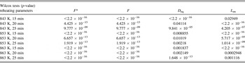
To validate the use of image analysis methods, and meanwhile to reduce the amount of manual interventions, one of the grain shape parameters, the prediction of average grain roundness made by the IPP software (denoted F*) and Eq. (2) (denoted F) were compared. The Wilcox test results are given in Table II. As can be seen, the p-value of (F* & F) for a given reheating process is quite high, nearly 1. Since p > 0.05, there is no significant difference in the mean value of roundness predicted by IPP (F*) and Eq. (2) (F). Therefore, the measured results of area (A n ) and perimeter (P n ) of solid grains obtained from software IPP are reliable, which can be reasonably substituted in Eq. (1)–(3) for the quantitative investigation on the semisolid microstructure evolution of casting aluminum alloy.
The p-values from the Wilcox tests (α = 0.05) for the parameter of roundness of solid grains measured results from IPP and the mathematic theoretical results by using Eq. (2) at the same experimental condition.

III. RESULTS AND DISCUSSION
A. Qualitative comparison between traditional and two-stage processes
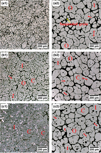
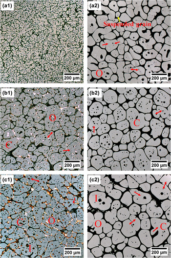
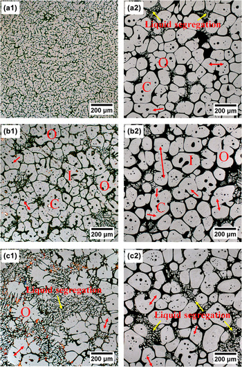
Figures 5–7 show a comparison between the traditional and two-stage reheating processes to prepare feedstock for thixoforming. Each figure provides the microstructures resulting from using a different reheating temperature (843, 853, and 863 K), and within each figure the reheating time is increased from top to bottom (15, 20, and 25 min). The micrographs on the left (right) were taken from samples processed using the traditional (two-stage) reheating process. Overall, it can be seen from this series of micrographs that solid grains coarsen gradually with increased temperatures and holding times, through two main mechanisms of coalescence and Ostwald ripening. Coalescence occurs by boundary migration when two adjacent grains with similar size share a common crystallographic orientation, Reference Chen, Zhao, Chen and Wang2 as indicated by two-way arrow in Figs. 5–7. Large coalescence resulted from small solid grains merging into larger ones to reduce the interfacial energy was noticed in the semisolid microstructure (marked as ‘C’ in Figs. 5–7). Ostwald ripening was also observed to occur, with large grains growing at the expense of small ones, as indicated by one-way arrow in Figs. 5–7. Active small grains with larger surface area to volume ratio will attain a lower energy state by transforming into large grains. Another form of coalescence that was observed in the micrographs is the agglomeration of two or more small neighbor grains (marked as ‘O’ in Figs. 5–7). These were likely to have contained some small liquid droplets, labeled as “I” in Figs. 5–7. From a mechanics point of view, this entrapped liquid behaves differently as compared to the free liquid at the grain boundaries. In general, it clearly shows that the traditional reheating microstructure exhibits larger variation in grain morphology as compared to the two-stage reheating microstructure. While this is seen in all the figures, it is especially clear in the micrographs at holding time of 20 min [(b1) in Figs. 5–7]. These results demonstrate that the two-stage reheating process provides better microstructure control, which will be a benefit during industrialization.
Microstructures of 356.0v obtained from traditional (a1, b1, and c1) and two-stage (a2, b2, and c2) reheating process prepared at 843 K with different soaking periods: (a) 15 min; (b) 20 min; (c) 25 min.

Microstructures of 356.0v obtained from traditional (a1, b1, and c1) and two-stage (a2, b2, and c2) reheating process prepared at 853 K and with different soaking periods: (a) 15 min; (b) 20 min; (c) 25 min.

Microstructures of 356.0v obtained from traditional (a1, b1, and c1) and two-stage (a2, b2, and c2) reheating process prepared at 863 K with different soaking periods: (a) 15 min; (b) 20 min; (c) 25 min.

Figure 5 shows the semisolid microstructures obtained after reheating at 843 K for various holding times (15, 20, and 25 min) using both reheating methods. The traditional reheating microstructures are shown in (a1, b1, and c1). As can be seen, at a relatively low reheating temperature and short holding time of 15 min (a1), the traditional reheating microstructure presented as irregular and finely-divided dendritic grains with tiny distinct grain boundaries. This micrograph is similar to the initial microstructure, Fig. 1, indicating that although some liquid has melted, there has been only limited grain coarsening. With increased holding time to 20 min, (b1), rosette-like grains have formed. Clearly, the grain boundaries continued to move and coalesce to reduce system energy. Much of the liquid is now also entrapped within the grains. With a further holding time of 25 min, (c1), the grains have further coarsened and a bright third-phase particle, assumed to be blocky Si, has appeared at the grain boundaries or entrapped in solid grains. In comparison to the traditional reheating process, the microstructure obtained from the two-stage process (i.e., first reheat to the liquidus, then cool to 843 K) is significantly different. There appears to be more liquid present, and further the bright phase is not present. With increasing holding time to 20 (b2) and then 25 (c2) min, the solid grains gradually coarsened and also became spherical in shape. At 25 min, it can be observed that a few larger “liquid islands” have formed. These individual grains were relatively coarse in size and irregular in shape; coalescence then played a significant role in the formation of these coarsening grains.
Figure 6 shows all of the micrographs resulting from using a reheating temperature of 853 K. Using the traditional reheating process, the grains are rosette-like in shape after 15 min of heating, (a1), with a small amount of remelted liquid at the grain boundaries. With increasing time to 20 min and then 25 min, (b1 and c1), the grains have grown and coalesced together and more of the material has melted. Although the traditional reheating at 853 K required 25 min of hold time, the bright precipitates still cannot be fully melted. This phase, if it remained after thixoforming, could result in component embrittlement. Further, these particles may prevent further coarsening. So it is necessary to melt these precipitates to further improve the morphology of semisolid microstructure and optimize the thixotropic behavior of resulting parts. Further, as the holding time is extended to 25 min (c1), large drops of entrapped liquid are seen to be contained in coarsening solid grains, and the bright precipitates seem to act as obstacles to grain spheroidization. The liquid is also nonuniformly distributed around the irregular-shaped solid grains.
Two-stage reheating microstructures obtained from first reheating the material to the liquidus and then cooling to 853 K are shown in Figs. 6(a2), (b2), and (c2). The microstructure resulting from a holding time of 15 min, (a2), indicates that the holding time is too short to complete the grain spheroidisation process. There are a few smaller solid grains suspending in the liquid (i.e., suspended grain in structure), which dissolve quickly to reach a new equilibrium condition due to its high curvature. As the holding time is increased to 20 min, the solid grains tend to be more globular and uniform in size, demonstrating that the two-stage reheating microstructure, (b2), reaches an equilibrium state, with near-spherical primary phase dispersed uniformly in a liquid matrix. The certain amount of free liquid surrounding grain boundaries is in favor of a reduction of fluid internal fiction, which is beneficial to the rearrangement and spherical solid grains during processing. The surface tension and boundary energy act as the driving force for the movement and rotation of solid grains. Consequently, this shows that the two-stage reheating process can successfully produce the desirable semisolid microstructure, as shown in Fig. 6(b2), which is consisted of well-developed completely spheroidal grain and uniformly distributed free liquid at grain boundaries, with only a little amount of liquid entrapped in the solid grains. As the holding time is further increasing to 25 min, (c2), solid grain coarsening to an irregular grain shape is noted. This phenomenon is due to the higher surface energy of the inner crystallites of solid grains, which is contributed to the dissolution of solid grains with entrapped liquid. For this reason, the low curvature and spherical solid grains are translated into rosette-like solid grains with large curvature.
Figure 7 shows the comparative semisolid microstructures with temperature increased to 863 K for the two reheating processes. Compared to the traditional microstructures at the lower reheating temperatures, rosette type grain boundaries are visible in the microstructure even after a holding time of 15 min, (a1). At longer holding times, (b1 and c1), the traditional reheating microstructures still contain the third-phase precipitation structure, and the solid grains are coarsening, meanwhile a large number of small sized solid grains are present within the liquid at boundaries, which have a great influence on the homogeneous of microstructure. The two-stage microstructures from reheating to 863 K are shown in Figs. 7(a2), (b2), and (c2). The shape of solid grains is improved (in terms of round-ness) as compared to the traditional microstructure. Further, a lower amount of small suspended grains are evident within the free liquid. Due to the higher temperature, the solid–liquid interfacial energy will be increased, which will enhance the rate of liquid formation. Diffusion of the solute atoms in the solid–liquid phase is fast as a result of continually growing of liquid phase at high reheating temperature. Meanwhile, liquid segregation is clearly evident in both traditional and two-stage produced microstructures, with more of the small solid grains suspended in free liquid. It is also observed that liquid segregation and grain coarsening increased as holding time is increased, as shown in Fig. 7.
Generally, the coarsening mechanisms of semisolid microstructure during reheating process are coalescence and Ostwald ripening. The driving force of coarsening mechanism during reheating is the reduction in interfacial energy between the solid and liquid phases. Reference Wang, Ji, Hu and Xu35 Grain coarsening by coalescence is dominant at short time at a relatively low liquid fraction, while Ostwald ripening plays an increasingly important role with rising of reheating temperature and holding time. At high liquid fractions, the contribution of Ostwald ripening and coalescence lead to a minor entrapped liquid in semisolid microstructures, as labelled ‘I’ in Figs. 5–7. As the reheating temperature increases, both coarsening mechanisms are significantly enhanced as a consequence of boost solid–liquid interface energy and atom diffusion ability. In addition, it can be expected that the liquid entrapped inside of solid grains coarsen as well, with several small adjacent dispersive liquid droplets aggregated into one large central pool. Simultaneously, a local zone of some of particles melted to form irregular solid grain shape, as shown in Figs. 5–7.
B. Quantitative metallography
To quantify the differences between the traditional and two-stage reheating microstructures, the fraction of entrapped liquid, grain perimeter, and area were measured using the IPP software. From this data, the equivalent diameter and roundness of the solid grains were calculated using Eq. (1) and (2), while the coarsening rate constant was estimated from Eq. (3). The fraction entrapped liquid, which represents the possibility of causing defect, was also recorded. Ostwald ripening and coalescence both contribute to the coarsening of grains in a competitive state. These two mechanisms have opposite effects on entrapped liquid, Ostwald ripening leads to a loss of entrapped liquid and coalescence leads to liquid entrapment. Reference Babaghorbani, Salarfar, Nili-Ahmadabadi, Kang, Kim and Lee36
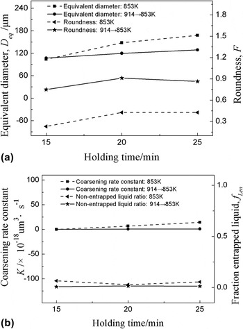
The equivalent diameter, roundness, and coarsening rate constant of solid grains as a function of holding time at 853 K were analyzed by comparing the traditional and the new two-stage reheating processes produced microstructures. The results of this analysis are shown in Fig. 8. Overall, it is observed that the equivalent diameter (D eq) is smaller, the roundness of grain shape (F) is closer to 1, the coarsening rate (K) is lower and there is less entrapped liquid (f 1,en) in the two-stage reheating microstructure as compared to the traditional process. Thus, quantitative metallographic results have demonstrated that the proposed two-stage method can obtain better semisolid microstructural morphologies.
Dependence of (a) equivalent diameter, roundness and (b) coarsening rate constant and fraction entrapped liquid on holding time at a temperature of 853 K from the traditional and two-stage reheating process for 356.0v casting alloy.

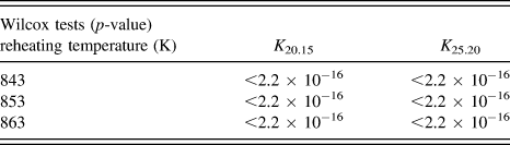
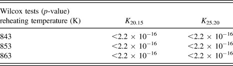
The statistical analysis of the quantitative metallography is shown in Tables III and IV. As can be seen, all p-values of the Wilcox tests for microstructure morphology parameters (F, D eq, f 1,en, and K) are below the significance level of 0.05, namely the null hypothesis is refused and their mean value are not equal to each other. This provides strong evidence that the microstructure morphology parameters (F, D eq, f 1,en, and K) obtained from two-stage reheating process are markedly different from those obtained from the traditional reheating processes (p < 0.05). In terms of thixoforming, the semisolid microstructure is significantly improved by two-stage reheating process.
The p-values from the Wilcox tests (α = 0.05) for the microstructure morphology parameters measured from the traditional and two-stage reheating samples prepared with the same temperatures and holding periods.

The p-value of Wilcox tests (α = 0.05) for coarsening rate constant during two different reheating processes.
Overall, based on quantitative metallography and statistical analysis results, it can be observed that there is a considerable difference in microstructure between images, and thus considerable grain evolution is occurring as a function of reheating temperature and reheating time. It was found that it is difficult to produce the well-behaved spherical microstructure by the traditional reheating process for Al–Si casting aluminum alloy. However, the two-stage reheating microstructures exhibited relatively spheroidal and homogeneously distributed grains with a liquid phase that was located along the grain boundaries, and without the bright third-phase precipitates. The two-stage reheating process developed in this work consists of two successive stages to ensure the formation of near-spherical primary solid grains with uniform surrounding liquid phase. The heating to nearly the liquidus as a first stage is crucial to ensure the fully melting of third-phase precipitates at the grain boundaries and to allow for the further optimization of the semisolid microstructure morphology of Al–Si casting aluminum alloy.
IV. CONCLUSIONS
The thixoforming process offers an alternative production route for structural components used in the automobile and aerospace industries. The experimental results presented in this work provide some guidance in allowing this process to be applied to industrial Al–Si casting alloys. The main conclusions are noted below.
-
(1) A two-stage reheating process offers significant advantages over the traditional reheating process in creating feedstock for thixoforming from industrial Al–Si casting alloys.
-
(2) The first stage of the two-stage process, heating to the liquidus temperature, ensures the complete melting of the third-phase precipitates, and assists in producing small solid grains, and uniformly distributed and near-spherical grains with the liquid phase dispersed uniformly around the solid.
-
(3) The second stage allows for some grain coarsening, and for the creation of near-spherical grains. Statistically, the equivalent diameter of grains produced using the two-stage process were finer and much more spherical as compared to the traditional process.
-
(4) The coarsening and entrapped liquid contents were measured and noted as also being lower for the two-stage reheating microstructure compared to that of traditional process.
ACKNOWLEDGMENTS
This work is funded by the National Natural Science Foundation Project of China (51374109). The authors would like to thank to Analyst Shou Peng Xie in Shanghai Lian He Credit Information Service Co., Ltd for his assistance in statistical analysis and helpful discussions.