I. INTRODUCTION
With excellent comprehensive mechanical property, the granular bainite steel is commonly applied for manufacturing large gears, girth-welding pipelines, and bridges.Reference Chen, Tang, Liu and Wang1–Reference Bhole, Nemade, Collins and Liu3 The outstanding performance of the steel is associated with the microstructure which consists of equiaxed bainitic matrix, martensite (M), and austenite (A). The martensite and austenite structures, which can be recognized as M/A island, contribute a significant improvement for the tensile strength of the steel.Reference Qiao, Liu, Yu and Gao4,Reference Wang, Hsieh and Liou5
In many cases, the components made up of the granular bainitic gradually lose effectiveness and need repairing after being used for a certain period of time.Reference Liu, Lv, Xu and Xia6–Reference Yang, Zhang, Hu, Bao and Jiang10 Several methods can be utilized to restore its working shape, dimension, and properties for the failed component, while the hardfacing method by flux-cored arc welding (FCAW) is one of the best effective ways.Reference Buchely, Gutierrez, León and Toro11–Reference Kirchgaßner, Badisch and Franek13
Several investigations have achieved some success in improving the mechanical properties of the bainite. Chen and GuoReference Chen, Tang, Liu and Wang1,Reference Guo, Guo, Guo, Wang, Li and He14 have found that the granular bainite could be obtained by adding alloy element Mo or Zr as the dopant. Qiao et al.Reference Qiao, Liu, Yu and Gao4 investigated the effects of amount and dimension of M/A island on the mechanical properties of the bainite. Wang and YangReference Wang, Yang, Bai and Fang15,Reference Yang and Bhadeshia16 recognized that the strength of bainite can be effectively improved by the increasing of undercooled austenite stability. Moreover, the positive effects of alloy element V on the microstructure and properties of the bainite steel were investigated in our previous work.Reference Chen, Xing, Wang, Zhou, Ren, Yang and Yang17
On potential method, the rare earth (RE) elements and the related oxides are applied to improve the mechanical properties of the alloys and the coatings.Reference Fu, Xiao, Kuang, Jiang and Xing18–Reference Chen, Li, Sun and Li23 GarrisonReference Garrison and Maloney24 investigated the effects of La2O3 on the morphology of inclusions, and recognized that La2O3 can modify the size and morphology of the inclusions. Moreover, the RE oxides can react with oxygen and sulfur to form oxides, sulfides, and oxysulfides, which in turn improve the toughness and ductility of the coatings.Reference Wang, Lin, Ji and Lan21–Reference Chen, Li, Sun and Li23,Reference Wang, Lin, Yue, Liu, Guo and Wang25,Reference Cai, Liu, Wei and Cheng26 By the added La2O3, the mechanical properties of the granular bainitic coating could be effectively improved.Reference Wang, Chen, Yang, Hao, Dan, Yang and Yang27
Comparatively, RE element Y with more active chemical properties has paid extensive in metallurgical industry recently. RaduReference Radu, Li and Llewellyn28 investigated the effect of Y2O3 on Stellite 21 alloy, and found that Y2O3 can promote stress-induced martensitic transformation and improve the wear-resistance of the alloy. RiffardReference Riffard, Buscail, Caudron, Cueff, Issartel and Perrier29 inferred that the antioxygenic property on the surface of 304 stainless steel can be improved by ion implantation Y.
The mentioned investigations have laid a good foundation for the systematical research in the effects of RE oxides on microstructure and the properties of the coatings. However, there were few reports about the effect of RE oxides Y2O3 on granular bainitic coatings.
In this paper, the granular bainitic coatings with different Y2O3 additives were fabricated by FCAW, and the effects of Y2O3 additive on phase transition regulation and mechanical properties of the bainitic coating were investigated in detail.
II. EXPERIMENTAL MATERIALS AND METHODS
Before welding, the base metals of ASTM 1045 steel (100 × 100 × 10 mm3) were cleaned. Flux-cored wire, which consisted of outer H08A steel strip and wrapped powder, was prepared. The wrapped powder was mixed by graphite, ferrochrome, ferrosilicon, ferromanganese, ferromolybdenum, and nickel. Moreover, to investigate the effect of Y2O3 on microstructure and mechanical property of the bainitic coating, the Y2O3 additive of 0, 0.99, 1.96, and 3.85 wt% was also added into the wrapped powder, respectively.
The bainitic coatings were fabricated by FCAW. The parameters of the welding process are listed in Table I. The chemical compositions of the coatings, which were determined by x-ray fluorescence spectrometry (Advant/p-381X, Thermo Fisher Scientific, Shanghai, China) and infrared carbon sulfur analyzer (CS-8800, Wuxi Jinbo Electronic & Electrical Equipment Co., Ltd, Wuxi, China), which are listed in Table II.
Parameters of the welding process.

Chemical compositions of the bainitic coatings.

The surface of the specimens was treated with rubdown and polishing with 4% nitric acid in both horizontal and vertical faces. The microstructure of the coatings was observed by optical microscopy (OM Axiovert 200 MAT, Carl Zeiss AG, Heidenheim/Germany) and scanning electron microscopy (SEM Hitachi S4800, Hitachi Limited, Tokyo, Japan). The etching solution of 4% nital was used to reveal the microstructure of the coatings. Prior austenitic grain boundaries were examined by OM, which were displayed with an etchant composed of picric acid, sodium dodecyl benzene sulfonate, and distilled water by heating to 60 °C in a waterbath for 1–2 min. Image analysis method was applied for austenite grain size statistics. Referred to ASTM E112,30 the grains are counted with known area by selecting 20 OM images with 100× standard magnification from each specimen.
Phase structures of the coatings were determined by x-ray diffraction (XRD; D/max-2500/PCX, Rigaku Corporation, Tokyo, Japan). During the test, 40° < 2θ < 120° with a step size of 0.02° was set; dwell time was 2 s.
Microhardness tester (FM-ARS 9000, Future-Tech Corporation, Tokyo, Japan) with a load of 100 gf (0.98 N) was conducted for hardness determination. The tensile test specimens with ϕ1.5 mm and length of 10 mm parallel section were machined from the coatings. The wear resistance test was operated with friction and wear testing machine (CETR UMT-3, Bruker Corporation, Campbell, California). Figure 1 shows the schematic diagram of CETR UMT-3. The specimens were cut into 10 × 10 × 20 mm3 from the coatings and the experimental parameters are listed in Table III. The phase precipitation curve and continuous cooling curve (CCT) of the bainitic coating was calculated by computer coupling of phase diagrams.
Equipment schematic of the CETR UMT-3.

Friction and wear test parameters.

III. RESULTS AND ANALYSIS
A. Microstructure characterization and phase compositions
The microstructure of the bainitic coatings with different Y2O3 additives are shown in Fig. 2. It can be seen from Fig. 2(a) that, the microstructure of coating without Y2O3 additive consists of granular bainite and proeutectoid ferrite (PF). The PF precipitates from the grain boundary of the austenite and the shape of the PF is abnormal large block. With the increased Y2O3 additive, the large block PF is gradually refined, as shown in Fig. 2(b). The microstructure of coating with 1.96 wt% Y2O3 contains the refined PF distributed in granular bainite matrix, as shown in Fig. 2(c). While, compared with microstructures in Figs. 2(c) and 2(d), the refinement effects of the PF become slack with more added Y2O3.
Microstructures of the hardfacing alloys with different Y2O3 additions: (a) 0 wt%; (b) 0.99 wt%; (c) 1.96 wt%; (d) 3.85 wt%.
The phase structures of the coatings are shown in Fig. 3. From Fig. 3(a) it can be concluded that α-Fe of body-centered cubic (BCC) structure and γ-Fe of face-centered cubic one are determined. Figure 3(b) shows the detail of electron diffraction pattern of γ-111. It is evidenced that with the increased Y2O3 additive, the diffraction peak intensity of retained austensite (RA) is weakens, which indicates that the amount of RA is decreased. Besides, the detail of electron diffraction pattern of α-220 is shown in Fig. 3(c). With the increased Y2O3, the peak of α-220 is shifted to the low angle and the peak of α-220 is asymmetric. According to the Bragg's law, the interplanar crystal spacing of α-220 becomes wide, and at least two different phases of BCC structure exist in the microstructure, as shown in Fig. 3(c). Therefore, it can be inferred that the fraction of martensite in the M/A island is increased with the increased of Y2O3 additive.
XRD patterns of the hardfacing alloys with different Y2O3 additions (a) and its amplification of γ-111 diffraction peaks (b) and α-220 diffraction peaks (c).
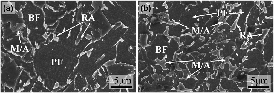
The SEM morphologies of the bainitic coatings without and with 1.96 wt% Y2O3 additions are shown in Fig. 4. From Fig. 4(a), the microstructure of the coating without Y2O3 contains PF, bainite ferrite (BF), RA, and M/A islands, which consist of martensite and austenite. The microstructure of the coating with 1.96 wt% Y2O3 additive is shown in Fig. 4(b). Compared with Fig. 4(a), it can be seen that the PF is efficiently refined and the fractions of BF and M/A are increased. It can be inferred that, the microstructure of the coating is obviously refined and well-distributed by the added Y2O3 additive.
SEM morphologies of the bainitic coatings without (a) and with 1.96 wt% Y2O3 additive (b).
The grain size distribution of austenite is shown in Fig. 5. From the inserted optical figure in Fig. 5, the grain size of austenite in the coating without Y2O3 is relatively coarse and non-uniform, and the average gain size of austenite is 51.2 µm. With the increased Y2O3, the grain size of austenite in bainitic coating is gradually refined and more uniform. Remarkably, the grain size of austenite is 40.1 µm when the coating contains 1.96 wt% Y2O3 additive, as shown in Fig. 5(c). While, the refinement of the austenite is not obvious by adding even more Y2O3 additive (>1.96 wt%), as shown in Fig. 5(d). Therefore, it can be concluded that the austenite in coating can be most effectively refined and uniformed by a proper Y2O3 additive of 1.96 wt%.
Grain size of austenite in hardfacing alloys with different Y2O3 additions: (a) 0 wt%; (b) 0.99 wt%; (c) 1.96 wt%; (d) 3.85 wt%.
B. Mechanical properties
Figure 6 shows the micromorphology and microhardness distribution in vertical cross-section of the bainitic coatings without and with 1.96 wt% Y2O3 additive. As shown in Figs. 6(a) and 6(b), the micromorphology of the coatings in vertical cross-section consists of hardfacing layer, weld dilution zone, heat affected zone (HAZ), and substrate metal in sequence. The results have proven that the flux-cored wires can be performed quite well in the arc surface welding. A few of slag defects between successive layers can be detected, while the porosity defects cannot be observed in the hardfacing layers. The microhardness distribution of the coatings in vertical cross-section over a 7 × 4 mm2 area is shown in Figs. 6(c) and 6(d). The microhardness of the HAZ in both coatings with and without Y2O3 is HV 190–HV 210 and the weld dilution zone in each coating has a constant thickness. Compared with the base metal, the hardness of the coatings was improved significantly, meanwhile the hardness distribution interval of the coating with 1.96 wt% Y2O3 additive has a relative improvement.
Micromorphology of the bainitic coatings in vertical cross-section without (a) and with 1.96 wt% Y2O3 additive (b) and microhardness distribution of the coating without (c) and with 1.96 wt% Y2O3 additive (d).
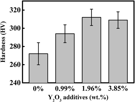
The microhardness of the coatings is shown in Fig. 7. The microhardness of the coating without Y2O3 additive is HV 272 ± 13. With the increased Y2O3 additive, the microhardness of the coating is obviously increased. The microhardness is reached to HV 295 ± 10 and HV 312 ± 8 when the added Y2O3 additive is reached to 0.99 wt% and 1.96 wt%, respectively. Moreover, the mean squared error of the microhardness is also improved, which indicates that the average microhardness and its differentiation of the coating can be improved by adding Y2O3 additive.
Microhardness of the bainitic coatings with different Y2O3 additives.
The engineering stress–strain curves and the SEM fractograph (inserted figures) of the bainitic coatings without and with 1.96 wt% Y2O3 additive are shown in Fig. 8. The engineering stress–strain curves of the coatings are practically superposed at the elastic deformation stage, which indicates that the elastic modulus of the coating cannot be influenced by Y2O3 additive. The coatings without and with 1.96 wt% Y2O3 additive are continuous yielding during tensile tests, and the plastic deformation zone of the coating is relatively large.
Engineering stress–strain curves of the bainitic coatings without and with 1.96 wt% Y2O3 additive and its SEM fractographs (inserted figures).
When Y2O3 additive is modified from 0 wt% to 1.96 wt%, the tensile strength of the coating is increased from 764 MPa to 885 MPa and elongation from 28.5% to 32.5%. It is blindingly obvious that the tensile strength and elongation of the coating are obviously improved by Y2O3 additive. Moreover, the SEM fractographs of the coatings without and with 1.96 wt% Y2O3 additive are shown in inserted figures of Fig. 8. The dimples of uneven size in both coatings without and with Y2O3 prove that the coating is of a typical ductile fracture. Furthermore, the dimple depth is increased significantly by the added Y2O3, which indicates that the toughness of the coating is improved simultaneously.
Figure 9 shows the coefficient of friction (COF) curves and the height loss curves of the bainitic coatings with different Y2O3 additives. The effectiveness of Y2O3 on COF of the coatings is quit limited. The exact COF value is decreased from 1.22 to 1.10, when the Y2O3 additive in the coating is increased from 0 wt% to 1.96 wt%, as shown in Fig. 9(a). While as shown in Fig. 9, it can be concluded an approximation result that the height loss is decreased with the increased Y2O3, which means that the wear-resistance of the bainitic coating can be effectively improved by the added Y2O3 additive.
COF (a) and the height loss (b) of the hardfacing alloys with different Y2O3 additions.
IV. DISCUSSION
A. Transformation of undercooled austenite
The phase precipitation and CCT curves of the bainitic coating without Y2O3 additive are shown in Fig. 10. From Fig. 10(a), the δ-Fe precipitates from liquid phase (L) as the temperature cooled to 1490 °C during air cooling process after FCAW. With reducing temperature, the primary austenite is transformed via peritectic reaction (δ-Fe + L = γ-Fe). When temperature is cooled to the ferrite transformation star temperature (F S), the PF begins to precipitate from austenite, as shown in Fig. 10(b). The growth rate of ferrite is generally controlled by carbon diffusion in austenite. When temperature is cooled to the bainite transformation star temperature (B S), the BF transforms during air cooling process. In the BF transformation, the carbon partitions into the residual austenite from BF.Reference Caballero, Miller, Babu and Garciamateo31,Reference Militzer, Pandi and Hawbolt32 The islands in granular bainite originally consist of carbon-rich austenite and partially martensite transformed during subsequent cooling process when temperature is cooled to the martensite transformation start temperature (M S).
Phase precipitation curve (a) and CCT curve (b) of hardfacing alloy.
B. Refinement mechanism of primary austenite
The SEM fractograph of the bainitic coating with 1.96 wt% Y2O3 additive as well as the EDS result of the inclusion are shown in Fig. 11. From the detected composition result, the alloy element Y can be observed in the inclusions.
SEM fractograph of hardfacing alloy with 1.96 wt% Y2O3 addition (a) and the EDS result of inclusion (b).
The two-dimensional lattice misfit theory. During heterogeneous nucleation, the nucleation with δ < 6% is the most effective, while that with δ = 6–12% is middle-effective, and that with δ > 12% is ineffective during heterogeneous nucleation.Reference Bramfitt33 The mathematical model can be expressed as follows:
 $$\delta _{{{\left( {hkl} \right)}_{\rm{n}}}}^{{{\left( {hkl} \right)}_{\rm{s}}}} = \sum\limits_{i = 1}^3 {\left[ {{{\left( {{{\left| {\mathop {{d_{{{\left[ {uvw} \right]}_{\rm{s}}}}}}\nolimits^i \,\cos \,\theta - \mathop {{d_{{{\left[ {uvw} \right]}_{\rm{n}}}}}}\nolimits^i } \right|} \mathord{\left/ {\vphantom {{\left| {\mathop {{d_{{{\left[ {uvw} \right]}_{\rm{s}}}}}}\nolimits^i \,\cos \,\theta - \mathop {{d_{{{\left[ {uvw} \right]}_{\rm{n}}}}}}\nolimits^i } \right|} {\mathop {{d_{{{\left[ {uvw} \right]}_{\rm{n}}}}}}\nolimits^i }}} \right. \kern-\nulldelimiterspace} {\mathop {{d_{{{\left[ {uvw} \right]}_{\rm{n}}}}}}\nolimits^i }}} \right)} \mathord{\left/ {\vphantom {{\left( {{{\left| {\mathop {{d_{{{\left[ {uvw} \right]}_{\rm{s}}}}}}\nolimits^i \,\cos \,\theta - \mathop {{d_{{{\left[ {uvw} \right]}_{\rm{n}}}}}}\nolimits^i } \right|} \mathord{\left/ {\vphantom {{\left| {\mathop {{d_{{{\left[ {uvw} \right]}_{\rm{s}}}}}}\nolimits^i \,\cos \,\theta - \mathop {{d_{{{\left[ {uvw} \right]}_{\rm{n}}}}}}\nolimits^i } \right|} {\mathop {{d_{{{\left[ {uvw} \right]}_{\rm{n}}}}}}\nolimits^i }}} \right. \kern-\nulldelimiterspace} {\mathop {{d_{{{\left[ {uvw} \right]}_{\rm{n}}}}}}\nolimits^i }}} \right)} 3}} \right. \kern-\nulldelimiterspace} 3}} \right]} \times 100\% \quad {\rm{,}}$$
where (hkl)s is a low-index plane of the substrate; uvw s is a low-index direction in (hkl)s; (hkl)n is a low-index plane in the nucleated solid; uvw n is a low-index direction in (hkl)n;  ${d_{{{\left[ {uvw} \right]}_{\rm{n}}}}}$ is the interatomic spacing along uvw n;
 ${d_{{{\left[ {uvw} \right]}_{\rm{s}}}}}$ is the interatomic spacing along uvw s; θ is the angle between the uvw s and uvw n.
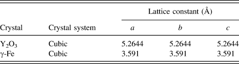
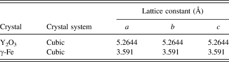
The lattice constants of Y2O3 (Ref. Reference Katagiri, Ishizawa and Marumo34) and austenite are listed in Table IV. The crystal relationship between Y2O3 and γ-Fe is shown in Fig. 12, and Table V lists the calculated result of the lattice misfit δ between the face (100) of Y2O3 and face (100) of austenite. The two-dimensional lattice misfit between the face (100) of Y2O3 and face (001) of austenite is 3.67%, which indicates that Y2O3 as heterogeneous nuclei of austenite is most effective. Therefore, the primary austenite in the coating can be refined by Y2O3 additive.
Lattice constants of Y2O3 and austenite.
Crystal relationship between Y2O3 and γ-Fe.
Misfit between the Y2O3 and austenite.
C. Formation of PF and bainite
The process of ferrite transformed from austenite can be subdivided into two stages, which are ferrite nucleation and growth. M. Militzer et al.Reference Militzer, Pandi and Hawbolt32 investigated ferrite transformation from austenite and found that ferrite can be nucleated at austenite grain corners for slow cooling rates and small austenite grain sizes. Meanwhile, the growth rate of the ferrite can be decreased due to the refinement of austenite grain size. In the bainitic coating, the large block ferrite precipitates on the austenite grain boundary. With the added Y2O3 additive, the austenite grain can be refined, and the nucleation number and growth rate of the PF are decreased gradually with the increased Y2O3 and the PF can be refined significantly.
The fraction of the ferrite in the coating without Y2O3 additive is relatively higher than that with Y2O3 additive. The formation of ferrite leads to a large number of carbon diffusing into the supercooled austenite and the bainite transformation is inhibited.
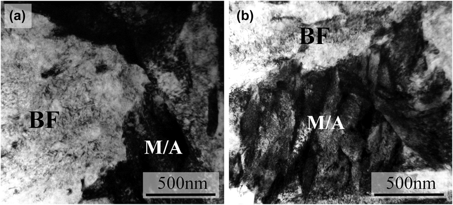
Moreover, carbon can be trapped at dislocations in the vicinity of the austenite–ferrite interface and higher amounts of carbon remain in solid solution in BF.Reference Yakubtsov, Poruks and Boyd2 The fraction of BF is increased with the increased Y2O3, which in turn generates the amount of carbon in solid solution of undercooled austenite reducing. Additionally, a part of undercooled austenite can be transformed into martensite when the coating is cooled to room temperature, and therewith increasing the proportion in the M/A island. Figure 13 shows the typical TEM morphology of the bainitic coatings without and with 1.96 wt% Y2O3. It can be seen from the TEM result that the block structure belongs to granular bainite, which always contains BF and M/A. Meanwhile, dislocation can be observed in the BF, and with the added Y2O3 additive in the bainite, the fraction of martensite in the M/A is increased obviously, as shown in Fig. 13(b).
TEM morphology of the hardfacing alloys without (a) and with 1.96 wt% (b) Y2O3 additions.
V. CONCLUSIONS
The effect of Y2O3 on the microstructure and mechanical property of PF/granular bainitic coating was investigated. Main conclusions are as follows:
(1) The microstructure of the coating consists of granular bainite and PF. The PF can be efficiently refined and the fractions of BF and M/A can be increased by the added Y2O3 additive. Meanwhile, the large number of the dislocation martensite is transformed in M/A.
(2) The primary austenite in the bainitic coating can be refined by Y2O3. The grain size of primary austenite is decreased from 51.2 µm to 40.1 µm with the increased Y2O3. According to Bramfitt two-dimensional lattice misfit theory, the lattice misfit between the face (100) of Y2O3 and face (001) of austenite is 3.67%, which indicates that Y2O3 as heterogeneous nuclei of austenite is most effective.
(3) With the increased Y2O3 additive, the hardness and the tensile strength of the coating is increased from HV 272 ± 13 to HV 312 ± 8 and from 764 ± 10 MPa to 885 ± 12 MPa, respectively. Moreover, the wear resistance of the coating with Y2O3 additive is increased simultaneously.
ACKNOWLEDGMENTS
This work was supported by the National Natural Science Foundations (Grant Nos 51271163 and 51471148), P. R. China, Hebei province natural science foundation of China (No. E2015203156), and program for Hebei province Basic Research Foundation of China (16961008D).