1 Introduction
In considering the flow over a flexible bluff body, the flow direction is typically not oriented normal to the body axis because the body may deflect due to fluid forcing, tethering or gravity. When this occurs, the direction of the vorticity vector at separation changes, affecting the formation of the wake and the fluid–body interaction. In general, the body may also be curved, so that the angle of incidence will vary along the span of the body.
It is now well known that, for a straight cylinder inclined at an angle to the flow, the Reynolds number at the onset of vortex shedding, the Strouhal number and cylinder drag are correlated with the yaw angle
 $\unicode[STIX]{x1D703}$
(Hanson Reference Hanson1966; Van Atta Reference Van Atta1968; Ramberg Reference Ramberg1983). The ‘independence principle’ is often invoked to describe the relationship of vortex shedding with
 $\unicode[STIX]{x1D703}$
(see figure 1
a) in this quasi-two-dimensional approximation; the velocity component normal to the body (
 $U\cos \unicode[STIX]{x1D703}$
) dictates the fluid forcing instead of the free-stream velocity (
 $U$
). The independence principle appears to work well for
 $\unicode[STIX]{x1D703}\leqslant 35^{\circ }$
(Van Atta Reference Van Atta1968), and possibly as large as
 $60^{\circ }$
(Zhao, Cheng & Zhou Reference Zhao, Cheng and Zhou2009). As
 $\unicode[STIX]{x1D703}$
increases, the axial velocity component more strongly influences the direction of the vorticity vector at separation (Ramberg Reference Ramberg1983), and significant axial flow is generated on the leeward side. The mean spanwise velocity in the wake can reach
 $0.08U$
for
 $Re_{D}=7200$
for
 $\unicode[STIX]{x1D703}=45^{\circ }$
(Zhou et al.
Reference Zhou, Razali, Zhou, Chua and Cheng2009), and for
 $15^{\circ }\leqslant \unicode[STIX]{x1D703}\leqslant 45^{\circ }$
, the streamwise vorticity can increase by up to 70 % compared to that of a cylinder oriented normal to the flow (
 $\unicode[STIX]{x1D703}=0^{\circ }$
) (Zhou et al.
Reference Zhou, Wang, Razali, Zhou and Cheng2010; Wang et al.
Reference Wang, Razali, Zhou, Zhou and Cheng2011). Here,
 $Re_{D}=DU/\unicode[STIX]{x1D708}$
, where
 $D$
is the body diameter and
 $\unicode[STIX]{x1D708}$
is the kinematic viscosity.
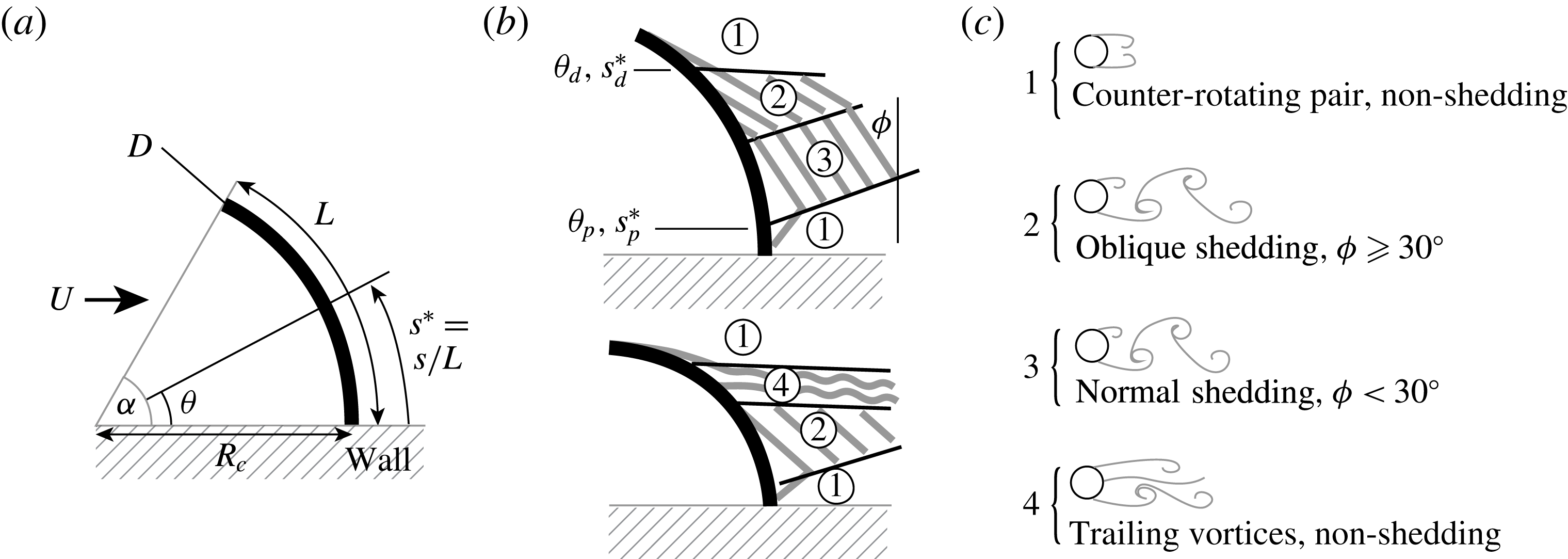
Coordinate system and flow regimes for a straight inclined cylinder in the ‘concave’ orientation (free end pointed upstream) at low and high angles of inclination
 $\unicode[STIX]{x1D703}$
. Flow is from left to right, and shed vortices are shown in grey. Four flow regimes are identified based on the vortex shedding condition (Ramberg Reference Ramberg1983).

It is also well understood that the end conditions of the cylinder introduce three-dimensional effects that influence wake formation. For straight cylinders normal to the flow, vortex filaments bend towards the cylinder endpoints for most finite end conditions (wall-bounded, free or contaminated free surfaces). Vortex shedding is suppressed in the immediate vicinity of the end conditions, and away from the ends the vortex filaments can be oriented oblique to the cylinder (Slaouti & Gerrard Reference Slaouti and Gerrard1981). Slaouti & Gerrard (Reference Slaouti and Gerrard1981) proposed that oblique shedding indicates that the three-dimensional effects of one end condition dominate over the effects of the other one. For cantilevered cylinders, the spanwise pressure gradient on the leeward side drives a flow that transports spanwise vorticity away from the free end, leading to oblique shedding or suppressed shedding (Park & Lee Reference Park and Lee2000; Afghan, Moulinec & Laurence Reference Afghan, Moulinec and Laurence2006). The shedding angle indicates the presence of a spanwise base pressure gradient and streamwise vorticity in the near wake of the cylinder; the base pressure gradient induces a spanwise flow in the near wake of oblique shedding but is absent in the case of normal shedding (Williamson Reference Williamson1989; Hammache & Gharib Reference Hammache and Gharib1991).
For inclined finite cylinders, the end constraints can cause departures from the independence principle. Ramberg (Reference Ramberg1983) visualized flows past an inclined cylinder of finite length
 $L$
with one wall-mounted end and one free end for
 $160\leqslant Re_{D}\leqslant 1000$
. When the free end of the cylinder pointed downstream (for comparison with the flow over curved cylinders, we will call this the ‘convex’ orientation), the vortex shedding was parallel to the cylinder except near the ends. When the free end of the cylinder pointed upstream (we will call this the ‘concave’ orientation), the different wake structures that were observed are summarized in figure 1(c). Far from the free end, the vortex filaments are shed at an angle
 $\unicode[STIX]{x1D719}$
(see figure 1
b) that is approximately equal to the yaw angle
 $\unicode[STIX]{x1D703}$
. This regime (regime 3) is denoted as ‘normal shedding’ because the vortex filaments are normal to the incident velocity. Close to the free end, however, a steady symmetric or asymmetric pair of counter-rotating vortices separates from the body, similar to what happens in the wake of pitched slender bodies of revolution (Hunt Reference Hunt1982; Zilliac, Degani & Tobak Reference Zilliac, Degani and Tobak1991). This is the ‘non-shedding’ regime (regime 1). Sometimes an intermediate region of ‘oblique shedding’ (regime 2) spans the region between regimes 1 and 3, where vortex filaments are inclined at a large angle to the body. Oblique shedding generally occurs at lower yaw angles and at a lower frequency than normal shedding. At higher yaw angles, the oblique shedding regime (regime 2) is replaced by a region of separated but non-shedding vortices that lift away from the body and align with the free stream, appearing as sinuous trails in the wake. This is the ‘trailing vortices’ regime (regime 4).
For a rigid inclined cylinder, the transition between regimes 2 and 4 occurs at sufficiently high
 $\unicode[STIX]{x1D703}$
, which is a function of Reynolds number
 $Re_{D}$
and tip geometry, with vortex shedding (regime 2) dominating at higher Reynolds numbers. For a flat-ended cylinder, the transition occurs for
 $\unicode[STIX]{x1D703}=35{-}45^{\circ }$
for
 $Re_{D}\leqslant 300$
(Ramberg Reference Ramberg1983). The aspect ratio
 $L/D$
also determines spanwise wake formation, and so the free end influences the distal location separating non-shedding regime 1 from shedding regimes 2 and 3, and the relevant parameter is
 $s_{d}^{\ast }=s_{d}/L$
(the dimensionless axial distance from the cylinder root, see figure 1). For straight cylinders, the distance from the free end
 $1-s_{d}^{\ast }$
has been shown to be self-similar across cylinders of different aspect ratios at the same incidence angle
 $\unicode[STIX]{x1D703}$
(Montividas, Reisenthel & Nagib Reference Montividas, Reisenthel and Nagib1989). The shedding wake boundary is also delineated by the parameter
 $s_{p}^{\ast }=s_{p}/L$
, where
 $s_{p}$
is the spanwise location at which vortex shedding occurs proximal to the cylinder root.
Here, we are interested in the corresponding wake formation regimes of a rigid curved cylinder, which experiences three-dimensional effects introduced by local variation in yaw and by finite end conditions. The independence principle would suggest that the Strouhal number and shedding frequency would vary locally, but prior studies of a convex-oriented curved cylinders (
 $L/D\approx 20$
,
 $Re_{D}\leqslant 500$
) showed vortex shedding at a constant angle and frequency, and at higher
 $Re_{D}=3900$
(Miliou et al.
Reference Miliou, De Vecchi, Sherwin and Graham2007) the vortex lines were slightly curved but not parallel to the body (Gallardo, Andersson & Pettersen Reference Gallardo, Andersson and Pettersen2014). The spanwise flow induced by the end constraints yields significant differences in the wake structure between the convex and concave orientations, as found for straight cylinders. Vortex shedding was suppressed in the wake of a concave curved cylinder (
 $Re_{D}\leqslant 500$
) or distorted in the wake of a U-shaped cable (
 $Re_{D}\leqslant 2450$
) (Ahmed Reference Ahmed2001; Miliou et al.
Reference Miliou, De Vecchi, Sherwin and Graham2007). The non-shedding wake was characterized by separated counter-rotating vortices similar to wake regime 1 for inclined straight cylinders. Tuft and flow visualizations showed that near-wake flow was diverted from higher to lower local yaw (Surry Reference Surry1965; Ahmed Reference Ahmed2001). Miliou et al. (Reference Miliou, De Vecchi, Sherwin and Graham2007) found a stagnation pressure gradient that drove an axial flow (up to 20 % of the free-stream velocity), and suggested that the vortex shedding was suppressed because less spanwise vorticity was generated due to the axial flow. In contrast, the axial flow on a convex cylinder directs flow from low to high yaw, augmenting spanwise vorticity in high-yaw regions (Miliou et al.
Reference Miliou, De Vecchi, Sherwin and Graham2007).
To examine the flow over curved cylinders in more detail, we use flow visualization to examine the wakes of rigid cylinders of varying (i) curvature, (ii) aspect ratio and (iii) Reynolds number. Convex and concave orientations were considered, but the concave case is intrinsically more interesting and it is therefore given more emphasis below. We are interested in identifying the various flow regimes that appear in the wake, what their distinctive features are in terms of spatial extent, Strouhal number and vortex structure, and how these regimes vary with Reynolds number. We anticipate that modestly curved cylinders will behave similarly to straight cylinders, while cylinders of higher curvature will have regions of suppressed vortex shedding. As found for straight inclined cylinders, we expect that changing the aspect ratio of the curved cylinders will affect the region over which the free end has a significant effect. Finally, the Reynolds number is expected to counter the finite end effects, where inertial forces tend to drive vortex shedding.
2 Experiments
Experiments were conducted in a closed-loop, free-surface water channel with a test section that is 0.3 m deep, 0.46 m wide and 2.4 m long. The flow in the test section was conditioned upstream with a honeycomb flow straightener and two mesh screens of increasing fineness; the average turbulence intensity at the velocities in this study was measured to be between 1.5 and 2.8 %. Each curved cylinder was immersed such that the cylinder root was at the free surface and the free end was closer to the bottom of the channel. The turbulent boundary layer thickness was estimated to be
 ${\sim}$
5 cm; with an immersion depth of 6–19 cm, the free end of the cylinder was sufficiently far from the boundary layer. A free-surface condition was used at the cylinder root; the free surface was smooth and free of surface waves. Further discussion of the influence of the free surface can be found in appendix A. For all of the data presented below, we will invert the images in accordance with the conventional orientation for inclined bodies such that the free end is at the top of the image.
The cylinder has an arclength
 $L$
and diameter
 $D$
, and in varying the arc angle
 $\unicode[STIX]{x1D6FC}$
the radius of curvature
 $R_{c}$
varies (figure 2). The dimensionless axial distance
 $s^{\ast }$
begins at the cylinder root and extends to the free end. The spanwise position can be described by the angle swept out by
 $s^{\ast }$
(with respect to the horizontal), which represents the local inclination angle from a normally oriented cylinder, and is thus denoted as
 $\unicode[STIX]{x1D703}$
. Three cylinders of two different diameters
 $D_{0}=3.18~\text{mm}$
and
 $D_{1}=6.35~\text{mm}$
and aspect ratios were tested over a range of Reynolds numbers, as given in table 1. To maintain a smooth free-surface condition, the maximum velocity was constrained, which restricted the range of Reynolds numbers explored for the smaller-diameter (
 $D_{0}$
) cylinder.
Coordinate system and flow regimes observed for curved cylinders in the concave orientation (free end pointed upstream) at low and high angles of swept arc
 $\unicode[STIX]{x1D6FC}$
. Flow is from left to right and shed vortices are shown in grey. Four flow regimes are identified based on the vortex shedding condition.
The cylinders were bent from zinc–tin or lead–tin solder alloys to a template of the desired curvature and aspect ratio. There were some imperfections in the bending process and in the mounting of the cylinder shaft to the water channel, resulting in small deviations from the desired curvature; the actual average arc angles are listed in table 1. Flatness tolerance was approximately 1 mm, corresponding to a maximum curvature error of 1 %. The agreement between our visualizations and prior computational results (Miliou et al.
Reference Miliou, De Vecchi, Sherwin and Graham2007) for the highest-curvature case indicates that any local inconsistencies introduced by the bending process are of secondary effect. For convenience, we will reference the nominal arc angle
 $\unicode[STIX]{x1D6FC}$
in discussing the results. We did not observe flow-induced vibrations; the ratio of the fluid forces to the elastic forces,
 $\unicode[STIX]{x1D6F1}=\unicode[STIX]{x1D70C}U^{2}L^{4}/ED^{4}$
, is small, where
 $E$
is the Young’s modulus (
 ${\sim}10~\text{GPa}$
for metals).
Experimental parameters for flow in a water channel. Uncertainty in
 $Re_{D}$
reflects resolution uncertainty in the channel speed control.

The wakes were visualized using electrolytic precipitation (Smits & Lim Reference Smits and Lim2000). A 10 mA current was applied between the cylinder anode and two downstream honeycomb screens that acted as the cathode. A schematic is shown in figure 3. A reflective white precipitate was generated at the cylinder surface that was convected with the flow. The wake was imaged both in the plane of curvature of the cylinder and also in cross-section at selected spanwise locations with either a Nikon DSLR or a Redlake MotionXtra HG-LE camera; data were converted to 8-bit monochrome images where applicable. The wake was illuminated with an argon-ion continuous-wave laser sheet (514 nm) generated by a cylindrical lens. When imaging the wake in the plane of curvature, the laser was first defocused with a spherical lens to illuminate a volume. At least 15 s of wake visualization were acquired in each case; this duration was sufficient to capture tens of vortex shedding cycles when shedding was observed.
Experimental configuration with the curved cylinder mounted at the free surface. A current is applied between the cylinder (anode) and downstream honeycomb screens (cathode) to generate a white precipitate that follows the flow and is illuminated by a defocused laser sheet.

3 Image analysis
Eigenpictures for each flow visualization were computed with a low-dimensional image decomposition (Sirovich & Kirby Reference Sirovich and Kirby1987) of the associated image sequence. A sample image and the first eigenpicture of the image sequence is shown in figure 4(a,b). While the sample image contains many three-dimensional features, the eigenpictures appear to capture well the dominant shedding modes in the wake. An automated algorithm utilizing image processing tools in Matlab processed the eigenpictures to determine the shedding angle of the vortex filaments. The eigenpictures were converted to binary images, and the narrow objects in the binary images correspond to vortex filaments along the span with some discrepancies near the cylinder ends where the filaments interact; the orientations of the filament centrelines were identified with Matlab image processing (figure 4 c,d). The filament orientations were aggregated over either the first 20 eigenpictures or the least number of eigenpictures that cumulatively account for 50 % of the pixel intensity ‘energy’, whichever number was smaller. While determining the shedding angle manually would probably have resulted in higher precision in the shedding angle, an automated approach can quickly analyse a large collection of images.
(a) Sample snapshot from an image sequence. (b) One eigenpicture for the image sequence, with the leeward edge of the cylinder also shown. (c,d) The image-processed eigenpicture, with the vortex filament centrelines identified in red (c), and the local shedding angle of these filaments shown in blue (d). In this figure, as in all other visualizations (unless otherwise noted), flow is from left to right.

The shedding frequency was examined by conducting temporal Fourier transforms of the pixel intensity at fixed locations downstream of the cylinder. The spectra help to identify shedding frequencies that may change along the span of a cylinder, as could be expected with bimodal shedding. The spectra were averaged over pixel locations at positions (4–20)
 $D$
downstream in 0.5
 $D$
increments in the streamwise direction to yield a smooth spectrum, and then normalized by the maximum magnitude.
4 Wake characteristics
Example instantaneous visualizations of the wake of a curved cylinder in the convex or concave orientations are shown in figure 5. Wake visualization movies corresponding to this figure are available online at https://doi.org/10.1017/jfm.2017.884. as supplementary movies 1 and 2. The convex orientation displays vortex shedding along most of its span, whereas in the concave orientation strong spanwise flow on the leeward side results in counter-rotating vortex cores that are stationary close to the body along most of the span, followed by separated trailing vortices. For the concave orientation, the flow meets the free surface (at the bottom of the image) and is redirected to follow the free stream, similar to the flow observed by Surry (Reference Surry1965) and Ahmed (Reference Ahmed2001) near the centreline of their U-shaped cables. The discrepancies in wake behaviour between the two orientations are similar to those previously found by Surry (Reference Surry1965), Ahmed (Reference Ahmed2001) and Miliou et al. (Reference Miliou, De Vecchi, Sherwin and Graham2007). We begin with the convex orientation.
Wake visualizations for a cylinder of
 $\unicode[STIX]{x1D6FC}=75^{\circ }$
and
 $L/D=30$
at
 $Re_{D}=468$
. Flow is from left to right. (a) Convex orientation; (b) concave orientation.

5 Convex cylinders
Across the range of Reynolds numbers and aspect ratios explored in this study, the convex-oriented cylinder always exhibits vortex shedding along most of the span, extending from the proximal location of vortex shedding
 $s_{p}^{\ast }$
all the way to the free end (that is,
 $s_{d}^{\ast }=1$
). The markedly different wake behaviour from the concave orientation, as shown in figure 5, arises from the spanwise pressure gradient, which was demonstrated with both inclined and curved cylinders in prior studies (Hammache & Gharib Reference Hammache and Gharib1991; Miliou et al.
Reference Miliou, De Vecchi, Sherwin and Graham2007). In the convex orientation, the vortex filaments are inclined at a constant angle, while in the concave orientation they are slanted in the opposite (negative) direction, indicating that the spanwise pressure gradient also changes sign, so that in the convex case it runs from the cylinder root to the free end.
Strouhal number
 $St$
and average shedding angle
 $\unicode[STIX]{x1D719}$
for a convex cylinder with
 $D=D_{1}$
,
 $L/D=30$
as a function of Reynolds number
 $Re_{D}=UD_{1}/\unicode[STIX]{x1D708}$
. Here
 $\unicode[STIX]{x1D719}$
is a spanwise average, although it is approximately constant along the span, as seen in figure 5. Roshko’s (Reference Roshko1954) empirical relation for a cylinder for
 $Re_{D}>300$
is shown as a dashed (– –) line. The uncertainty shown is a pooled standard deviation of independent visualizations.

The spanwise pressure gradient drives spanwise vorticity from the cylinder root to the free end. In the cylinder root region the yaw angles are small, so by the independence principle this region would generate relatively high spanwise vorticity compared to streamwise vorticity. However, the upwash lowers the spanwise to streamwise vorticity ratio, resulting in oblique shedding.
The mean shedding angle and mean Strouhal number for the convex cylinder with
 $D=D_{1}$
,
 $L/D=30$
are shown in figure 6 (the results may be compared with those for the same cylinder in the concave orientation shown in figure 14). A shedding frequency for each spanwise pixel location in the image was calculated by weighting the peaks in the spectra; these were then averaged over the spanwise extent of shedding to calculate a spanwise Strouhal number. Spanwise Strouhal numbers from repeated tests were pooled to obtain a mean Strouhal number. The mean shedding angle was similarly obtained by pooling a spanwise average shedding angle. For convex cylinders at the same
 $Re_{D}$
, the vortex shedding was more oblique for higher arc angles
 $\unicode[STIX]{x1D6FC}$
, suggesting that the ratio of the spanwise to streamwise vorticity decreased and that a larger upwash occurred. Correspondingly, the Strouhal number for larger arc angles was smaller. As the Reynolds number increases, the overall spanwise vorticity production increases, leading to a decrease in shedding angle and increase in Strouhal number (
 $St$
). For the higher values of
 $Re_{D}$
, as the wake transitions to turbulence, the shedding characteristics approach those of a straight cylinder even at large arc angles. Owing to the modest aspect ratio of the cylinder and the finite end conditions, the Strouhal number of the straight cylinder is less than that given by Roshko’s empirical
 $St$
–
 $Re_{D}$
relation for a high-aspect-ratio cylinder with wall-bounded end conditions, which is also shown in figure 6 as a reference. Over the Reynolds-number range explored in our experiments (
 $Re_{D}\lesssim 900$
), the shedding angle
 $\unicode[STIX]{x1D719}$
was constant along the span, although we recognize that at higher Reynolds numbers the filaments may be curved (see Gallardo et al. (Reference Gallardo, Andersson and Pettersen2014) at
 $Re_{D}=3900$
).
6 Concave cylinders
For concave cylinders, the wakes generally resemble those found by Ramberg (Reference Ramberg1983) for inclined cylinders. The characteristics of the four spanwise wake regimes identified in figure 2 are shown in figure 7 for two different concave cylinders. Wake cross-sections are illustrated in appendix B. The oblique shedding regime (regime 2) and the normal shedding regime (regime 3) may occur separately or in tandem; the two regimes coexist in the image shown in figure 7(a). While the shedding regimes appear identical to those identified for an inclined cylinder (figure 1), for inclined cylinders the shedding regimes are defined by the relationship between the shedding angle and cylinder yaw angle, while for a curved cylinder the yaw angle is not fixed so the regimes are defined by the orientation of the vortex filaments with respect to the free stream. Hence ‘normal’ shedding is when the vortex filaments are oriented nearly normal to the free stream, and oblique shedding occurs at a shallower angle to the free stream.
Two non-shedding regimes can also be present in flow past concave cylinders. Regime 1 is always present adjacent to the free end, where the wake separates as two counter-rotating, stationary vortices. Regime 4, where the separated vortices lift off the body and become aligned with the free stream, is similar to the trailing vortex regime found for inclined cylinders at large yaw. In figure 5(b), when vortex shedding is suppressed, only regimes 1 and 4 are observed.
Visualizations of the flow past a concave cylinder for
 $L/D=60$
: (a)
 $\unicode[STIX]{x1D6FC}=30^{\circ }$
,
 $Re_{D}=234$
; (b)
 $\unicode[STIX]{x1D6FC}=75^{\circ }$
,
 $Re_{D}=309$
.

6.1 Effects of curvature
Curvature was found to have a profound effect on the vortex shedding in the wake. Figure 7 shows two curvatures experiencing different contributions from each wake regime. For a cylinder of low curvature (
 $\unicode[STIX]{x1D6FC}\leqslant 45^{\circ }$
) and high aspect ratio, the wake is dominated by oblique and normal shedding, similar to the effect of small yaw (
 $\unicode[STIX]{x1D703}\leqslant 25^{\circ }$
) on an inclined straight cylinder of similar aspect ratio (Ramberg Reference Ramberg1983). As the curvature increases, non-shedding (regimes 1 and 4) and oblique shedding (regime 3) regions increase in spanwise extent. A cylinder at large yaw (
 $\unicode[STIX]{x1D703}\geqslant 40^{\circ }$
) also demonstrated large non-shedding regions, but in that case regime 3 was replaced by regime 4 and normal shedding was recovered far from the free end. Broadly, the effects of large and small curvature on the wake of a curved cylinder have parallels to the effects of high and low yaw angles for a straight cylinder.
Locally, however, the wake of a curved cylinder does not necessarily resemble that of an equivalently inclined cylinder. For a curved cylinder, the local inclination angle gradually decreases from the free end to the cylinder root. Hence regions proximal to the cylinder root may be expected to produce larger regions of near-normal shedding. From the results shown in figure 7(b), we observe that this is not the case; near the cylinder root the shedding occurs at a large angle to the body even though locally the cylinder inclination is small. First, this observation suggests that a locally based version of the independence principle does not apply to curved cylinders. Miliou et al. (Reference Miliou, De Vecchi, Sherwin and Graham2007) reached a similar conclusion for convex curved cylinders. Second, oblique shedding at small local inclinations suggests that the downwash from the free end is larger than that for an inclined cylinder, since the streamwise vorticity must be relatively large with respect to the spanwise vorticity in the wake to generate oblique vortex filaments. The shedding angle reflects the direction of the vorticity vector at separation, and oblique shedding indicates a finite spanwise velocity compared to normal shedding, where the axial velocity is small (Hammache & Gharib Reference Hammache and Gharib1991). A schematic representation of oblique shedding is shown in figure 8, which shows that when there is finite downwash (
 $|u_{z}|>0$
), the resultant vorticity vector has a non-zero streamwise component (
 $|\unicode[STIX]{x1D714}_{x}|>0$
) which tilts the vorticity vector away from the line of separation on the cylinder.
Schematic representation of oblique shedding for a cylinder with incident velocity
 $U$
with axial downwash
 $u_{z}$
. When
 $u_{z}$
is finite, the resultant vorticity
 $\unicode[STIX]{x1D714}$
has both streamwise and spanwise components (
 $\unicode[STIX]{x1D714}_{x}$
and
 $\unicode[STIX]{x1D714}_{z}$
, respectively), causing vortices to roll up at an angle to the cylinder.

Spanwise location of the inception of vortex shedding for a cylinder of
 $L/D=60$
and
 $D=D_{0}$
expressed as (a) arclength
 $s_{d}^{\ast }$
and (b) local inclination angle
 $\unicode[STIX]{x1D703}_{d}$
.

For the
 $L/D=60$
cylinder, figure 9(a) presents the distal location of the inception of vortex shedding, expressed as
 $s_{d}^{\ast }$
(see figures 1 and 2) for the angles of curvature
 $\unicode[STIX]{x1D6FC}$
examined here. Over this Reynolds-number range, the size of the vortex shedding region does not significantly change, but increasing the curvature reduces the spanwise distance over which vortex shedding occurs. As shown in figure 9(b), the data collapse reasonably well when the inception point is instead represented by the local inclination angle
 $\unicode[STIX]{x1D703}_{d}$
, with an inception range of
 $20^{\circ }<\unicode[STIX]{x1D703}_{d}<35^{\circ }$
. This result suggests that, above a local inclination angle of
 $35^{\circ }$
, vortex shedding is not attainable for this particular aspect ratio. Above
 $35^{\circ }$
, we obtain either steady separated flow or trailing vortices, both of which were depicted in figure 7(b). A flat-tipped inclined straight cylinder shows a transition from a strictly bimodal oblique-normal regime to a mix of trailing and normal shedding vortices for inclination angles
 $25<\unicode[STIX]{x1D703}<40^{\circ }$
(Ramberg Reference Ramberg1983), which is in good agreement with our results. This limitation on
 $\unicode[STIX]{x1D703}_{d}$
varies with aspect ratio and only applies to the laminar wake regime (
 $Re_{D}\leqslant 460$
, see § 6.3). The spanwise size of the trailing vortex region is generally correlated with increasing Reynolds number but can vary in experiments by approximately
 $2D$
at a fixed Reynolds number. Prior work in the area of inclined axisymmetric bodies has noted the sensitivity of vortex formation near the body nose to flow disturbances and body asymmetries (see e.g. Lamont & Hunt Reference Lamont and Hunt1976), which are likely to cause the variation in the trailing vortices documented in this study.
In addition, cylinders with angles of curvature less than the limiting
 $\unicode[STIX]{x1D703}_{d}$
should experience vortex shedding at all Reynolds numbers relevant to vortex shedding, if the spanwise flow induced by the free end does not overwhelm free-stream inertial effects. At the lowest angle of curvature (
 $\unicode[STIX]{x1D6FC}=30^{\circ }$
), the free end appears to have an influence over
 $s^{\ast }=0.1$
to
 $0.2$
, but overall the area of vortex shedding is consistent over the range of
 $Re_{D}$
tested here and occupies most of the cylinder span (figure 9
a). We expect that the influence of the free end will grow with decreasing aspect ratio, as discussed in the next section.
6.2 Effects of aspect ratio
The aspect ratio dictates the spanwise influence of the end constraints. For inclined cylinders, the influence depends on the axial distance from the free end, and it varies inversely with
 $L/D$
(Montividas et al.
Reference Montividas, Reisenthel and Nagib1989). That is, if regime 1 is found over a certain spanwise distance for a particular cylinder, it will be half that distance for a cylinder of twice the aspect ratio, e.g. the dimensionless length
 $(L-s_{d})/D$
is constant. Similarly, the spanwise influence of the free end grows with diminishing aspect ratio for curved cylinders. Figure 10 shows the distal location of vortex shedding for an aspect ratio of
 $L/D=30$
expressed in terms of
 $s_{d}^{\ast }$
and
 $\unicode[STIX]{x1D703}_{d}$
. We see that the collapse of the data is better in terms of
 $\unicode[STIX]{x1D703}_{d}$
than
 $s_{d}^{\ast }$
. Vortex shedding at the higher curvatures (
 $\unicode[STIX]{x1D6FC}=75^{\circ },90^{\circ }$
) is suppressed entirely in this Reynolds-number range and is not shown. Our results are consistent with Miliou et al. (Reference Miliou, De Vecchi, Sherwin and Graham2007) who found no vortex shedding for
 $\unicode[STIX]{x1D6FC}=90^{\circ }$
and
 $L/D\approx 20$
at similar Reynolds numbers.
Spanwise location of the inception of vortex shedding for a concave cylinder with aspect ratio
 $L/D=30$
and
 $D=D_{0}$
, expressed as (a) arclength
 $s_{d}^{\ast }$
and (b) local inclination angle
 $\unicode[STIX]{x1D703}_{d}$
. Non-shedding experiments are not shown.

Compared to the results shown in figure 9, where
 $L/D=60$
, vortex shedding regions are constrained or non-existent for the lower aspect ratio. The upper limit for shedding location is
 $15^{\circ }\leqslant \unicode[STIX]{x1D703}_{d}\leqslant 30^{\circ }$
, slightly less than that found for
 $L/D=60$
but in the same range. The cylinders whose results are shown in figures 9 and 10 have the same diameter, so the similarity parameter for inclined cylinders would be equivalent to
 $x=(L-s_{d})$
being self-similar across aspect ratios. The similarity agrees for the lowest curvature
 $\unicode[STIX]{x1D6FC}=30^{\circ }$
, where
 $L-s_{d}\approx 0.2L$
for
 $L/D=60$
and
 $L^{\prime }-s_{d}^{\prime }\approx 0.2L^{\prime }=0.4L$
for
 $L^{\prime }/D=30$
. At higher curvatures, e.g.
 $\unicode[STIX]{x1D6FC}=60^{\circ }$
,
 $s_{d}^{\ast }$
remains almost the same, and the similarity parameter does not scale with the aspect ratio. Similarity may be more predictable at lower curvatures since the shedding dynamics is likely not to depart strongly from that of an inclined cylinder. As suggested in the previous section, the local yaw
 $\unicode[STIX]{x1D703}_{d}$
appears to be a more appropriate parameter to predict shedding regions across aspect ratios, decreasing with increasing
 $L/D$
.
Sample visualization (left), shedding angle profile (middle) and normalized frequency spectra (right) for a curved cylinder of
 $\unicode[STIX]{x1D6FC}=45^{\circ }$
for (a)
 $L/D=30$
and (b)
 $L/D=60$
. The shedding frequency is calculated as a weighted average of nearby peaks and is highlighted using a dashed line on the Strouhal spectra.
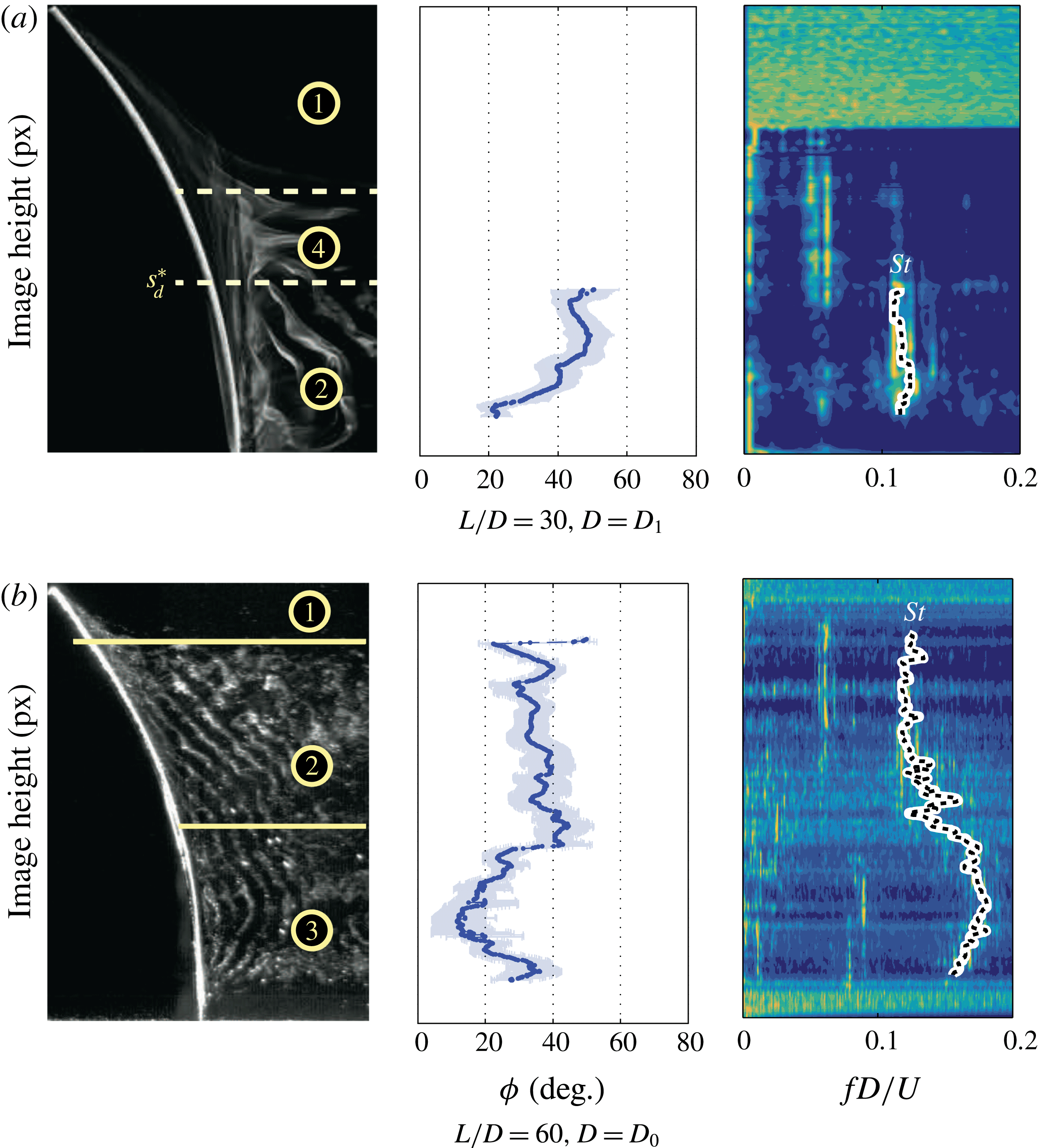
Because the aspect ratio influences the location where the non-shedding regime becomes a shedding regime, the distribution of shedding regimes will also vary with aspect ratio. For example, figure 11 compares the shedding regimes, shedding angles and wake frequencies found with
 $\unicode[STIX]{x1D6FC}=45^{\circ }$
for aspect ratios
 $L/D=30$
and
 $60$
. At the lower aspect ratio (figure 11
a), the influence of the free end restricts shedding along much of the cylinder span, and the spanwise pressure gradient forces oblique shedding (regime 2), except near the cylinder root where the vortices bend towards the cylinder. The Strouhal number in the oblique region is small,
 $St\approx 0.12$
, indicating that a significant streamwise vorticity component is induced by the pressure gradient. At the higher aspect ratio, bimodal shedding is observed with oblique and normal shedding regions because the spanwise influence of the free end diminishes with increasing aspect ratio. The oblique region (with
 $\unicode[STIX]{x1D719}\approx 40^{\circ }{-}45^{\circ }$
) exhibits a lower Strouhal number (
 $St\approx 0.12$
) similar to that seen for the lower-aspect-ratio cylinder, compared to the normal shedding region (regime 3), where
 $St\approx 0.18$
. The presence of the normal shedding region suggests that the axial flow in this region is relatively small compared to the cross-flow. The inverse correlation between shedding angle and wake frequency that holds for inclined cylinders appears to hold for curved cylinders as well (Ramberg Reference Ramberg1983).
6.3 Wake transition
Thus far, we have considered relatively low Reynolds numbers where the wake is laminar. Cylinders oriented normal to the flow and exhibiting normal shedding (with large aspect ratio and/or careful manipulation of the end conditions, as previously noted in the Introduction) will enter a transitional regime at
 $Re_{D}\approx 180$
where the wake becomes three-dimensional on small length scales, e.g.
 $O(D)$
(Williamson Reference Williamson1988; Noack & Eckelmann Reference Noack and Eckelmann1994). The transition is evident in the wake structure and the wake spectra. As transition begins, fine-scale structures appear on the primary vortices and the Strouhal number decreases. As
 $Re_{D}$
increases further, the fine-scale structures become less ordered, large-scale vortex dislocations become more common, the Strouhal number increases and the wake is considered turbulent.
Flow visualizations spanning the transitional regime for a concave cylinder of aspect ratio
 $L/D=30$
and diameter
 $D=D_{1}$
and varying
 $\unicode[STIX]{x1D6FC}$
: (a) laminar; (b) transitional; (c) turbulent. Curvature increases from left to right.

Local inclination angle
 $\unicode[STIX]{x1D703}_{d}$
of distal shedding (inception of regimes 1 or 2) for a concave cylinder
 $L/D=30$
and
 $D=D_{1}$
.

We observe a similar transition from laminar to three-dimensional wakes for curved cylinders where the critical
 $Re_{D}$
for transition depends on curvature. In figure 12, we show visualizations for a concave cylinder of
 $L/D=30$
and
 $\unicode[STIX]{x1D6FC}=30^{\circ }$
–
 $75^{\circ }$
of laminar, transitional and turbulent wakes found in the range
 $230<Re_{D}<916$
. In the laminar wake regime, the vortex filaments are generally smooth along their length and distinct (a). At locations of high
 $\unicode[STIX]{x1D703}$
, we encounter either steady vortex pairs (regime 1) or trailing vortices (regime 4). With a small increase in
 $Re_{D}$
(b), the flow transitions, with distorted primary vortices and streamwise vortex loops stretched between successively shed vortices for
 $\unicode[STIX]{x1D6FC}=30^{\circ }$
and
 $45^{\circ }$
, characteristic of the transitional instabilities observed for cylinders. The loops are not as regular nor do they persist downstream as would be found in normal shedding of a straight cylinder (Williamson Reference Williamson1996b
). The onset of transition is accompanied by an increase in the distal vortex shedding location
 $\unicode[STIX]{x1D703}_{d}$
, which can be seen in the visualizations and also in figure 13, which shows the variation of
 $\unicode[STIX]{x1D703}_{d}$
with increasing
 $Re_{D}$
. With another increase in
 $Re_{D}$
, the wakes are turbulent; there are no trailing vortices and the shed vortex filaments straighten and are encircled by fine three-dimensional structures that are generated at the surface of the cylinder as they separate from the body (figure 12
c). The distal yaw
 $\unicode[STIX]{x1D703}_{d}$
increases again to a value that persists for greater
 $Re_{D}$
(figure 13).
For higher angles of curvature
 $\unicode[STIX]{x1D6FC}=60^{\circ }$
or
 $75^{\circ }$
, intermediate instabilities were not observed in the transition to turbulence. The distal shedding location
 $\unicode[STIX]{x1D703}_{d}$
increased abruptly to a post-transition value (figure 13) also without an intermediate step. In straight cylinders, these instabilities are found over a narrow range of
 $\unicode[STIX]{x0394}Re_{D}\approx 60$
; our increments are
 $\unicode[STIX]{x0394}Re_{D}\approx 70$
and these transitional instabilities may have been entirely bypassed. Since the instabilities were observed over
 $\unicode[STIX]{x0394}Re_{D}\approx 140$
at the lower curvatures, however, another mechanism may be responsible for bypassing transition. For straight cylinders, the spanwise periodicity of modes A and B is attributed to characteristic length scales of the streamwise vorticity (Williamson Reference Williamson1996a
). Curved cylinders have spanwise-varying streamwise vorticity and may cause an inherent mismatch in the preferred wavelength of the instabilities, particularly at higher curvatures where the difference between the streamwise vorticity production at the higher and low yaw angles is more disparate, and preclude the instabilities entirely.
From figure 13, we can see that
 $\unicode[STIX]{x1D703}_{d}$
does not exceed
 $15^{\circ }$
–
 $25^{\circ }$
when the wake is laminar over a range of curvatures, consistent with
 $\unicode[STIX]{x1D703}_{d}$
found for other cylinders in this study (figures 9
b and 10
b). We can also see that the Reynolds number of transition increases with increasing curvature. In this study, the cylinder at
 $\unicode[STIX]{x1D6FC}=90^{\circ }$
did not transition, but we can expect that transition will be triggered at higher
 $Re_{D}$
than that studied here or in Miliou et al. (Reference Miliou, De Vecchi, Sherwin and Graham2007). Simply by increasing the curvature of a cylinder, transition can be delayed to a Reynolds number many times that expected for a straight cylinder. After transition,
 $\unicode[STIX]{x1D703}_{d}$
jumps sharply over a narrow range of
 $Re_{D}$
and asymptotes to a distal shedding location that corresponds to roughly 70 %–80 % of its spanwise length.
The jump in
 $\unicode[STIX]{x1D703}_{d}$
stems from three-dimensional perturbations in the wake. In the laminar wake regime, the vortex pair formed at the free end consistently drive flow towards the free end. Wake transition disrupts the spanwise flow, disrupting the production of streamwise vorticity and enhancing spanwise vorticity, increasing the region over which vortex shedding is found. Likewise, as spanwise vorticity dominates, the Strouhal number should recover. Figure 14 shows that a larger Strouhal number and smaller shedding angle are associated with smaller streamwise vorticity, as expected. Some of the trends in
 $\unicode[STIX]{x1D703}_{d}$
are mirrored in
 $St$
; this is particularly evident for
 $\unicode[STIX]{x1D6FC}=\{30^{\circ },45^{\circ }\}$
, where the shedding frequencies for
 $Re_{D}<470$
are markedly below
 $St_{0}$
, where
 $St_{0}$
is the Strouhal number for a straight cylinder with the same boundary conditions. Over the range
 $480\leqslant Re_{D}\leqslant 620$
, the Strouhal number recovers close to
 $St_{0}$
, and
 $\unicode[STIX]{x1D703}$
also increases. A similar trend in
 $St$
occurs for
 $\unicode[STIX]{x1D6FC}=60^{\circ }$
as well as over
 $540\leqslant Re_{D}\leqslant 620$
, though less apparent because the asymptotic
 $St$
is relatively small (
 $St\approx 0.7St_{0}$
).
Strouhal number and average shedding angle
 $\unicode[STIX]{x1D719}$
for concave cylinders and a straight cylinder of
 $L/D=30$
. Shedding angle is a spanwise average, and, as seen in figure 12, the shedding angle is approximately constant along the span for the concave cylinder. Roshko’s (Reference Roshko1954) empirical relation for a cylinder for
 $Re_{D}>300$
is shown as a dashed (– –) line.

In turn, the shedding frequency correlates with the shedding angle
 $\unicode[STIX]{x1D719}$
, as shown in figure 14. Across the full range of
 $Re_{D}$
and
 $\unicode[STIX]{x1D6FC}$
, shedding is preferentially oblique, and for oblique shedding angles the Strouhal number is significantly lower than
 $St_{0}$
. Increases in the Strouhal number, correlated with the wake transition, are found in tandem with decreases in the shedding angle with respect to the vertical axis. For
 $\unicode[STIX]{x1D6FC}=\{30^{\circ },45^{\circ }\}$
, an increase in
 $St$
across the wake transition corresponds to a
 $\unicode[STIX]{x0394}\unicode[STIX]{x1D719}=-20^{\circ }$
transition to vortex filaments that are oriented nearly normal to the free stream. Wake transition for a straight cylinder is also associated with a transition from oblique to normal shedding as the axial flow becomes very small (Hammache & Gharib Reference Hammache and Gharib1991).
7 Conclusions
We have explored the effects that axial flow induced by body curvature and finite end effects can have on vortex shedding past a rigid curved cylinder in concave and convex orientations. We have also investigated a range of Reynolds numbers and aspect ratios that yield a range of wake behaviours that have not been characterized by prior curved cylinder studies. The flow over a curved cylinder shares many of the characteristics of the flow over an inclined cylinder with a free end, such as the contrasting wake regimes observed for cylinders whose free ends are pointed against or with the flow. The wake similarity primarily arises from shared cylinder end conditions, which induce a pressure gradient along the cylinder. The spanwise pressure gradient is sensitive to the end conditions (e.g. endplates, nose geometries), which can result in changes in shedding (Ramberg Reference Ramberg1983; Hammache & Gharib Reference Hammache and Gharib1991). When the cylinder free end points against the flow (concave), the base pressure gradient induces a flow towards the fixed end, and the opposite occurs for the cylinder pointing with the flow (convex). In the former case, this results in downwash that reduces spanwise vorticity near the free end; and in the latter case, spanwise vorticity near the free end is increased through upwash.
The curved cylinder is set apart from an inclined cylinder in that its wake does not adhere to the independence principle. Features of the wake response such as Strouhal number, shedding angle and the inception of vortex shedding are less predictable for a curved cylinder than for a straight cylinder. For a straight cylinder, these quantities can be self-similar because the local incident flow is uniform along the span of the cylinder, and generally, away from the free end, the independence principle applies and any spanwise section of cylinder is considered to be equivalent to any other. In contrast, the vorticity production along any section of a curved cylinder, even away from the free ends, cannot be considered independent of the end conditions, as the transport and production of vorticity varies in the spanwise direction due to the pressure gradient.
For convex cylinders, the pressure gradient results in oblique shedding along most of the cylinder span. In contrast, for concave cylinders, the free end induces a secondary axial flow that reduces the length of the cylinder over which shedding occurs, and the magnitude of this axial flow appears to scale with the angle of curvature of the cylinder. The magnitude of the spanwise flow is indicated by preferential oblique shedding and by a decrease in the Strouhal number compared to normal shedding regions. In the laminar regime, the spanwise flow sets the upper limit on the spanwise location where shedding can occur. Depending on the angle of curvature, this shedding region can occupy a relatively small fraction of the span. The local inclination angle
 $\unicode[STIX]{x1D703}_{d}$
where vortex shedding is found is consistent between cylinders of different curvature and identical aspect ratio. Lowering the aspect ratio increases the spanwise influence of the axial flow, which decreases the local inclination angle
 $\unicode[STIX]{x1D703}_{d}$
; at sufficiently low aspect ratio, vortex shedding can be entirely suppressed along the span for a large range of Reynolds number. The similarity of the onset shedding angle
 $\unicode[STIX]{x1D703}_{d}$
among cylinders of different curvatures suggests that the magnitudes of the spanwise flows are locally self-similar.
Increasing the spanwise flow and streamwise vorticity through an increase in curvature or decrease in aspect ratio can also delay wake transition to turbulence. As the wake transitions to three-dimensional shedding, however, the extent of vortex shedding expands. The transition can be closely tied to changes in the wake frequency and in the shedding angle, corresponding to a reduction in the streamwise vorticity and spanwise flow. We can expect that the properties of vortex shedding will again be modified at significantly higher
 $Re_{D}$
as the shear layer transitions. Based on prior studies with symmetrically bent curved cylinders (Surry Reference Surry1965; Ahmed Reference Ahmed2001), we propose that our observations of the effects of curvature, aspect ratio and Reynolds number will also apply for symmetric cylinders concave to the flow. We note that these trends are restricted to the Reynolds numbers investigated here, where the boundary layer is laminar, and not necessarily to higher Reynolds number, where the shear layers are unstable or turbulent. For practical purposes, there is the strong implication that vortex shedding-related phenomena (e.g. flow-induced vibrations, fluctuating forces) can be minimized at modest Reynolds number with an appropriate choice of cylinder curvature and geometry.
Average spanwise distance from the free surface where vortex shedding was found (
 $s_{p}^{\ast }$
) for concave cylinders, with an example image showing
 $s_{p}^{\ast }$
marked with a yellow circle (lower centre). Here, as in all other figures, coloured bands correspond to variations found across experiments.

Supplementary movies
Supplementary movies are available at https://doi.org/10.1017/jfm.2017.884.
Appendix A. Free-surface boundary condition
Boundary conditions modify wake behaviour, as visualized by Slaouti & Gerrard (Reference Slaouti and Gerrard1981). Preliminary visualizations were conducted with a no-slip plane at the cylinder root. Because of the boundary layer, separation occurred farther from this end condition, and as such the transition between non-shedding and shedding regimes would occur at lower
 $Re$
and lower curvature. To increase the occurrence of vortex shedding, we chose to implement a free-surface boundary condition over a no-slip condition. The free surface was contaminated with ambient particles.
The effect of the contaminated free-surface boundary condition was quantified by determining the proximal boundary of vortex shedding (regimes 2 or 3) along the cylinder span, expressed as
 $s_{p}^{\ast }=s_{p}/L$
, where
 $s_{p}$
is the spanwise location at which vortex shedding occurs proximal to the cylinder root (see figures 1 and 2). In figure 15, we compare
 $s_{p}^{\ast }$
for all cylinders and Reynolds numbers studied. We see that the free surface inhibits vortex shedding for a distance up to
 $s_{p}\approx 6D_{0}$
for cylinders with diameter
 $D_{0}$
and differing aspect ratio (figure 15
b,c) and
 $s_{p}\approx 4D_{1}$
for cylinders of diameter
 $D_{1}$
(figure 15
a). So for a given aspect ratio
 $L/D$
, the dimensionless spanwise extent of the free-surface influence is smaller for a larger-diameter cylinder. For non-shedding cylinders exhibiting only regimes 3 or 4, the precipitate used in the flow visualization was found in the wake very close to the cylinder root and the free surface, as seen in figure 5(b). The spanwise flow from the free end towards the cylinder root appears to dominate any opposing flow in the vicinity of the cylinder root, drawing flow close to the surface before convecting downstream.
Appendix B. Wake cross-sections
The wakes in cross-section were visualized for the
 $L/D=30$
cylinder with the larger diameter (
 $D_{1}=6.35~\text{mm}$
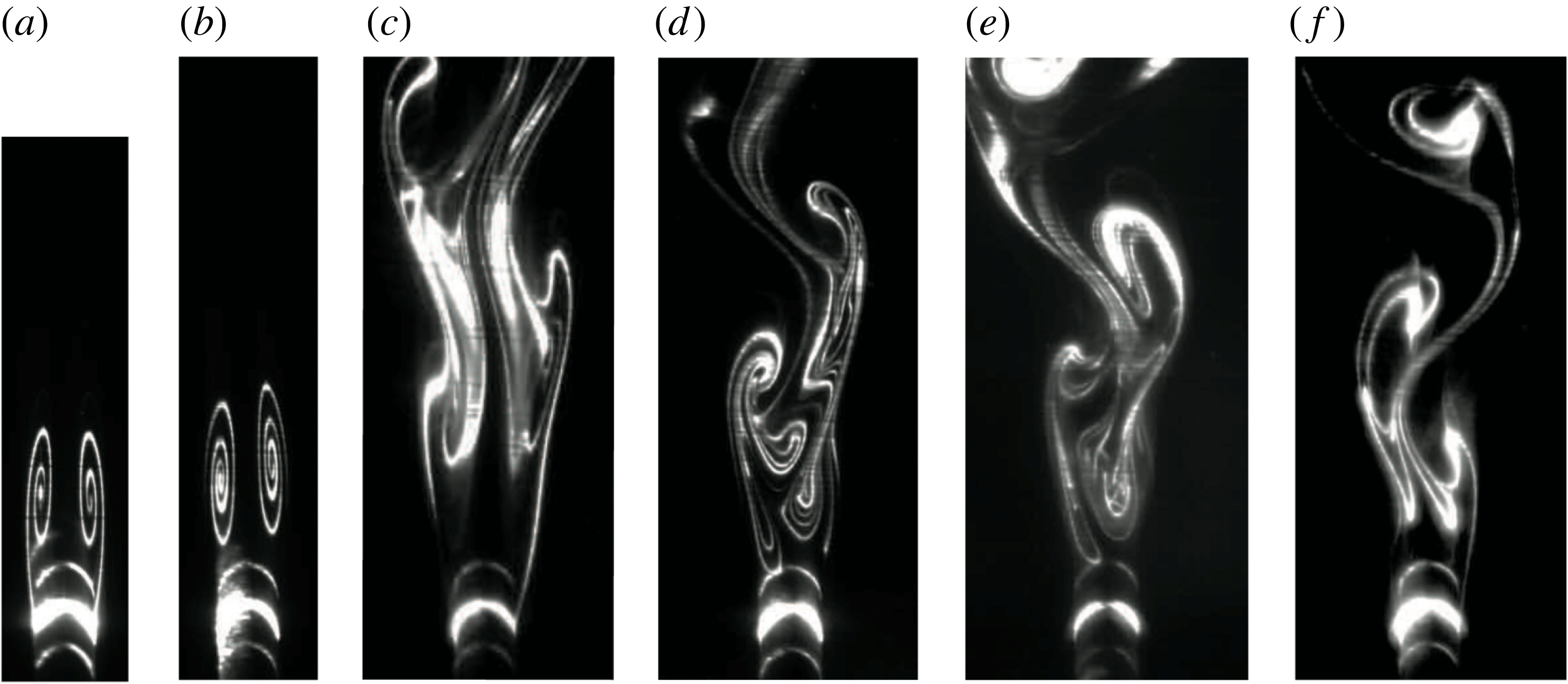
), which afforded better visualization. A diversity of possible wakes were observed, as shown in figure 16. Wake state (f) is a von Kármán vortex street that would be observed for wake regimes 2 and 3. The other wake states are schematically similar to the ones described for slender bodies of revolution (Lowson & Ponton Reference Lowson and Ponton1992). Wake state (a) is found for regime 1 and is steady; wake state (b) is also found for regime 1 and can be steady or quasi-steady. The asymmetry in (b) may result from small asymmetries or disturbances originating at the surface of the body (Moskovitz, Hall & DeJarnette Reference Moskovitz, Hall and DeJarnette1989; Degani & Schiff Reference Degani and Schiff1991). Wake states (c)–(e) are non-shedding wakes that would be observed for regimes 1 and 4 and resemble von Kármán streets but are non-shedding. Contrary to Hoang & Telionis (Reference Hoang and Telionis1991) and consistent with Zeiger, Vlachos & Telionis (Reference Zeiger, Vlachos and Telionis2001), these non-shedding wakes are unsteady and the vortex centres do not shed but instead meander at a frequency lower than the vortex shedding frequency.
Sample of possible wake states observed for the concave cylinder with
 $L/D=30$
and
 $D=D_{1}$
. All images are at approximately the same scale. Flow is from bottom to top, where the leeward face of the cylinder is strongly illuminated. (a) Symmetric counter-rotating pair. (b) Asymmetric counter-rotating pair. (c–e) Wakes with stationary (non-shedding) vortices. (f) Vortex street.