Nomenclature
- ST-SMC
-
Super-twisting sliding mode Control
- BTVFC
-
Bipartite time-varying formation control
- FT-ESO
-
Fixed-time extended state observer
- FTSO
-
Finite-time state observer
- NTSM
-
Non-singular terminal sliding mode
- NDI
-
Nonlinear dynamic inversion
- SMC
-
Sliding mode control
1.0 Introduction
Recent advancements in quadrotor technology have propelled quadrotors to the forefront of aerial systems due to their unique vertical takeoff and landing capabilities, precise hovering and exceptional manoeuvrability. These characteristics have enabled diverse applications ranging from military reconnaissance to precision agriculture. When deployed in formation, quadrotor systems demonstrate enhanced operational capabilities through improved mission efficiency, expanded coverage and robust fault tolerance [Reference Fan, Li, Zhang and Fu1, Reference Guo, Chen, Shi, Han and Lungu2]. However, complex wind field environments present significant challenges, including time-varying aerodynamic disturbances, strongly coupled nonlinear dynamics and underactuated system properties – all of which impose stringent requirements on the performance of formation control [Reference Cui, Xu, Chen and Yu3, Reference Zhang, Yan and Zhang4].
Building on these operational challenges, formation control strategies have evolved from traditional time-invariant approaches to sophisticated time-varying methods [Reference Kang, Luo, Xin, Cheng, Yang and Zhou5–Reference Jia, Chen, Wang, Wu and Xie7], making them adaptable to the changing requirements of tasks and scenarios. Recent research has further extended these frameworks to bipartite time-varying formation control (BTVFC), which is applicable to scenarios where the multi-agent system is divided into two antagonistic subgroups (e.g. target tracking and cooperative confrontation) [Reference Wang, Cao, Niu and Song8]. Different from traditional consensus-based formation control, BTVFC requires agents in the same subgroup to achieve state consensus and those in different subgroups to maintain a predefined anti-consensus relationship [Reference Zhao, Cui and Hua9–Reference Liu, Liu, Ma, Yang, Zhang, Yao, Zhang, Zhang and Xue11]. Moreover, in practical engineering applications, the formation shape often needs to be adjusted in real time according to task requirements, leading to the BTVFC problem for multiple quadrotors. The BTVFC problem not only needs to satisfy the bipartite constraint but also requires precise tracking of the time-varying formation trajectory, which brings great challenges to the control strategy design.
To address these challenges, significant advances have been made in multiple quadrotor formation control from fundamental robust and adaptive control approaches [Reference Derrouaoui, Bouzid, Belmouhoub and Guiatni12] to advanced sliding mode control (SMC) techniques. The SMC has evolved from chattering-prone conventional implementations to sophisticated variants: terminal SMC (TSMC) [Reference Gao, Liu and Liu13–Reference Derrouaoui, Bouzid, Doula, Boufroua, Belmouhoub, Guiatni and Hamissi15] for finite-time convergence, non-singular TSMC [Reference Cruz-Ortiz, Chairez and Poznyak16, Reference Wang, Ma, Gao, Zhou and Hua17] to resolve singularities and high-order SMC [Reference Levant18] for chattering suppression. Super-twisting SMC (ST-SMC) [Reference Yang, Ding and Ding19–Reference Zhang, Wang, Fan and Chen21] stands out for quadrotor applications, balancing performance and robustness. Notably, Ref. [Reference Qin, Zhao, Huang and Li22] extended this framework with a variable-gain ST-SMC, achieving predefined-time stability for quadrotor systems and rapid trajectory convergence under dynamic conditions. Nevertheless, existing ST-SMC-based formation control methods rarely consider the bipartite constraint and time-varying formation requirements simultaneously, and their anti-disturbance performance needs to be further improved when facing complex wind disturbances.
The extended state observer (ESO) is an effective tool to handle external disturbances and unmodeled dynamics, which has been integrated with SMC to enhance the anti-disturbance performance [Reference Ma, Wang and Han23–Reference Zhang, Zhao, Zhang, Niu, Zong and Xu25]. However, the convergence time of the traditional ESO depends on the initial state error [Reference Chen, Long and Li26]. For the BTVFC problem of multiple quadrotors, the fixed-time convergence of the observer is crucial to ensure the real-time performance and robustness of the control system, especially when the system is subject to large initial disturbances or parameter uncertainties. Therefore, the fixed-time extended state observer (FT-ESO) has been developed to estimate the wind-induced disturbance.
To address the aforementioned problems, a hierarchical ST-SMC integrated with FT-ESO is proposed to solve the BTVFC problem for multiple quadrotors under wind disturbances. The main contributions are summarised as follows:
-
• A novel competitive interaction modeling framework using explicit negative weight formulation is introduced, enabling effective BTVFC compatible with distributed tasks
-
• An advanced hierarchical control synthesis combining ST-SMC with fast non-singular TSMC to create a specialised solution for quadrotors’ BTVFC with enhanced performance characteristics
-
• A distributed FT-ESO developed to quantify aerodynamic disturbances, specifically forces and moments caused by wind fields
This paper is structured as follows. Section 2 introduces the theoretical groundwork, including signed graph theory, the quadrotor’s dynamic model, wind field model and essential definitions and lemmas. Section 3 details the systematic design of formation and attitude control laws, employing a hierarchical super-twisting sliding mode strategy to handle the BTVFC problem. Numerical simulations in Section 4 demonstrate the superior performance and key advantages of the newly developed control approach. Section 5 concludes with a summary and gives a future research direction.
2.0 Preliminaries
2.1 Notations
Let
 $\mathbb{R}^{n\times n}$
denote the space of
 $n\times n$
real-valued matrices, and
 $\mathbb{R}^{n}$
denote the space of n-dimensional real column vectors. The symbol
 $1_{N}$
denotes an N-element column vector where all entries equal unity. For any square matrix,
 $\lambda _{\min }$
and
 $\lambda _{\max }$
correspond to its smallest and largest eigenvalues, respectively. The operators
 $\max \{\cdot \}$
and
 $\min \{\cdot \}$
yield the supremum and infimum values of a set. The Kronecker product between matrices is denoted by
 $\otimes$
.
 $||\cdot ||_{p}$
indicates the p-norm, while
 $||\cdot ||$
specifically represents the Euclidean norm. Given
 $\eta =[\eta _{1},\cdots\;\!,\eta _{n}]^{T}\in \mathbb{R}^{N}$
and scalars
 $\rho ,\kappa \in \mathbb{R}$
, then define
 $| \eta | ^{\rho }=[| \eta _{1}| ^{\rho },\ldots ,| \eta _{n}| ^{\rho }]^{T},\tanh (\eta )=[\!\tanh (\eta _{1}/\kappa ),\cdots\;\!,\tanh (\eta _{n}/\kappa )]^{T}$
,
 $\left\lceil \eta \right\rceil ^{\rho }=\left[\left| \eta _{1}\right| ^{\rho }\tanh \left(\eta _{1}/\kappa \right),\cdots \right.\left.\left| \eta _{n}\right| ^{\rho }\tanh \left(\eta _{n}/\kappa \right)\right]^{T}.$
2.2 Signed graph theory
A directed signed graph
 $\mathcal{G}=\{\mathcal{V},\mathcal{E},\mathcal{A}\}$
models the communication links between networked quadrotors, where:
 $\mathcal{V}=\{v_{1},v_{2},\cdots\;\!,v_{n}\}$
represents the set of quadrotor nodes, and
 $\mathcal{E}\subseteq \mathcal{V}\times \mathcal{V}$
defines the links between quadrotors. Define the signed adjacency matrix
 $\mathcal{A}=[a_{ij}]\in R^{N\times N}$
, where
 $a_{ij}\in \{-1,0,+1\} \;:\; a_{ij}=1$
indicates a cooperative relationship;
 $a_{ij}=-1$
indicates a competitive relationship;
 $a_{ij}=0$
means no direct communication; diagonal elements satisfy
 $a_{ii}=0$
. For a signed digraph, its Laplacian matrix
 $\mathcal{L}=[l_{ij}]\in R^{N\times N}$
is defined by:
 \begin{align*} l_{ij} = \left\{ \begin{matrix} \begin{matrix} - a_{ij} &\quad i \ne j \end{matrix} \\[3pt] \begin{matrix} \sum\nolimits_{j \in N_i} \left| a_{ij} \right| &\quad i = j, \end{matrix} \end{matrix} \right. \end{align*}
where
 $\mathcal{N}_{i}$
denotes the neighbour set of the i-th quadrotor. Besides, define the pining matrix
 $\mathcal{B}=diag\{b_{1},\cdots\;\!,b_{N}\}$
with elements:
 $b_{i}\gt 0$
for the communication between i-th quadrotor and virtual leader; otherwise,
 $b_{i}=0$
.
Definition 1.
The structural balance property of a signed graph
 $\mathcal{G}=\{\mathcal{V},\mathcal{E},\mathcal{A}\}$
requires that
-
• The set
 $\mathcal{V}$
is divided into two mutually exclusive subsets.
$(\mathcal{V}_{1},\mathcal{V}_{2})$
-
• All intra-subset edges are non-negative
$(\begin{matrix} a_{ij} \gt 0 & \forall i,j \in \mathcal{V}_k \end{matrix} ,\, k = 1,2)$
-
• All inter-subset edges are non-positive
$(a_{ij} \lt 0 \quad \forall i \in \mathcal{V}_1,\; j \in \mathcal{V}_2)$


Assumption 1. A globally reachable node exists in the directed communication graph.
Lemma 1. [Reference Lu, Li, Ho, Cao, Lu, Li, Ho and Cao27] Under Assumption1, the matrix
 $\mathcal{H}=\sigma (\mathcal{L}+\mathcal{B})$
with
 $\sigma =diag\{\sigma _{1},\cdots\;\!,\sigma _{N}\}, \zeta =diag\left\{\zeta _{1},\cdots\;\!,\zeta _{N}\right\},\zeta _{i}=\frac{e_{i}}{f_{i}},e=\left[e_{1},\cdots\;\!,e_{N}\right]^{T}=\mathcal{H}^{-1}1_{N},f=\left[f_{1},\cdots\;\!,f_{N}\right]^{T}=\mathcal{H}^{-T}1_{N}$
guarantees that
 $\mathcal{U}=\zeta \mathcal{H}+\mathcal{H}^{T}\zeta$
is positive definite.
2.3 Quadrotor's dynamic model
The complete 6- degrees of freedom (DoF) model for the
 $i$
-th quadrotor under wind disturbances is formulated as:
 \begin{align} \begin{cases} \ddot{x}_{i}=m^{-1}\left[T_{1i}\left(\cos \phi _{i}\sin \theta _{i}\cos \psi _{i}+\sin \phi _{i}\sin \psi _{i}\right)+f_{wxi}\right]\\[4pt] \ddot{y}_{i}=m^{-1}\left[T_{1i}\left(\cos \phi _{i}\sin \theta _{i}\sin \psi _{i}-\sin \phi _{i}\cos \psi _{i}\right)+f_{wyi}\right]\\[4pt] \ddot{z}_{i}=m^{-1}\left[T_{1i}\cos \phi _{i}\cos \theta _{i}-mg+f_{wzi}\right]\\[4pt] \ddot{\phi }_{i}={J}_{x}^{-1}\left[\mathrm{T}_{2i}+\left(J_{y}-J_{z}\right)\dot{\theta }_{i}\dot{\psi }_{i}+M_{w\phi i}\right]\\[4pt] \ddot{\theta }_{i}={J}_{y}^{-1}\left[T_{3i}+\left(J_{z}-J_{x}\right)\dot{\phi }_{i}\dot{\psi }_{i}+M_{w\theta i}\right]\\[4pt] \ddot{\psi }_{i}={J}_{z}^{-1}\left[T_{4i}+\left(J_{x}-J_{y}\right)\dot{\phi }_{i}\dot{\theta }_{i}+M_{w\psi i}\right], \end{cases}\end{align}
where
 $f_{wi}=[f_{wxi},f_{wyi},f_{wzi}]^{\mathrm{T}}$
and
 $M_{wi}=[M_{w\phi i},M_{w\theta i},M_{w\psi i}]^{\mathrm{T}}$
denote the wind-induced disturbance force and moment vectors, respectively. And the meanings of other parameters can be found in Ref. [Reference Guo, Chen, Shi, Han and Lungu2].
By defining virtual control inputs
 $T_{pi}=[T_{xi},T_{yi},T_{zi}]^{\mathrm{T}}$
, the translational dynamics can be given by
 \begin{align} \begin{array}{l} \ddot{x}_{i}=T_{xi}+d_{xi}\\[3pt] \ddot{y}_{i}=T_{yi}+d_{yi}\\[3pt]\ddot{z}_{i}=T_{zi}+d_{zi}, \end{array} \end{align}
where
 \begin{align} \begin{array}{l} T_{xi}=m^{-1}\left[T_{1i}\left(\cos \phi _{i}\sin \theta _{i}\cos \psi _{i}+\sin \phi _{i}\sin \psi _{i}\right)\right]\\[3pt] T_{yi}=m^{-1}\left[T_{1i}\left(\cos \phi _{i}\sin \theta _{i}\sin \psi _{i}-\sin \phi _{i}\cos \psi _{i}\right)\right]\\[3pt] T_{zi}=m^{-1}T_{1i}\cos \phi _{i}\cos \theta _{i}-g \end{array} \end{align}
and
 \begin{equation}d_{xi}=f_{wxi}/m,d_{yi}=f_{wyi}/m,d_{zi}=f_{wzi}/m.\end{equation}
The rotational dynamic is alternatively formulated as:
 \begin{align} \begin{array}{l} \ddot{\phi }_{i}=\frac{T_{2i}}{J_{x}}+f_{\phi i}+d_{\phi i}\\[5pt] \ddot{\theta }_{i}=\frac{T_{3i}}{J_{y}}+f_{\theta i}+d_{\theta i}\\[5pt] \ddot{\psi }_{i}=\frac{T_{4i}}{J_{z}}+f_{\psi i}+d_{\psi i}, \end{array} \end{align}
where
 \begin{align} \begin{array}{l} f_{\phi i}=\left(J_{y}-J_{z}\right)\dot{\theta }_{i}\dot{\psi }_{i}/J_{x},d_{\phi i}=M_{w\phi }/J_{x},\\[4pt] f_{\theta i}=\left(J_{z}-J_{x}\right)\dot{\phi }_{i}\dot{\psi }_{i}/J_{y},d_{\theta i}=M_{w\theta i}/J_{y},\\[4pt] f_{\psi i}=\left(J_{x}-J_{y}\right)\dot{\phi }_{i}\dot{\theta }_{i}/J_{z},d_{\psi i}=M_{w\psi i}/J_{z}. \end{array} \end{align}
Virtual leader’s dynamic mode is
 \begin{align} \begin{array}{l} \dot{p}_{0}=v_{0}\\[3pt] \dot{v}_{0}=a_{p0}, \end{array} \end{align}
where
 ${p_0} = {\left[ {\begin{array}{*{20}{c}} {} {} {}{{x_0}}&\quad {{y_0}}&\quad {{z_0}} {}\end{array}} \right]^T},{v_0} = {\left[ {\begin{array}{*{20}{c}} {} {} {}{{{\dot x}_0}}&\quad {{{\dot y}_0}}&\quad {{{\dot z}_0}} {}\end{array}} \right]^T},{a_{p0}} = {\left[ {\begin{array}{*{20}{c}} {} {} {}{{a_{x0}}}&\quad {{a_{y0}}}&\quad {{a_{z0}}} {}\end{array}} \right]^T}$
And
 $a_{p0}$
is bounded, that is
 $||a_{\omega 0}||\leq \overline{a}_{\omega }(\omega =x,y,z)$
.
 $\overline{a}_{\omega }$
is a positive constant.
Assumption 2. Wind-induced disturbances affecting all DoF satisfy the bounded rate condition:
 \begin{equation}\left| \frac{d}{dt}d_{\omega i}\left(t\right)\right| \leq \overline{d}_{\omega },\forall \omega \in \left\{x,y,z,\phi ,\theta ,\psi \right\}\end{equation}
where
 $\overline{d}_{\omega }\gt 0$
denotes a known upper bound on the magnitude of each disturbance component.
Definition 2. The multiple quadrotors are said to achieve BTVFC in finite time, if
 \begin{align*} \left\{ \begin{matrix} \lim\nolimits_{t \to T_p} \left\| p_i - o_i - p_0 \right\| = 0,\; \forall i \in {V_1}, \\[3pt] \lim\nolimits_{t \to T_p} \left\| p_i - o_i + p_0 \right\| = 0,\; \forall i \in V_2 \end{matrix} \right. \end{align*}
 \begin{align*} \left\{ \begin{matrix} \lim\nolimits_{t \to T_v} \left\| v_i - \dot{o}_i - v_0 \right\| = 0,\; \forall i \in {V_1}, \\[3pt] \lim\nolimits_{t \to T_v} \left\| v_i - \dot{o}_i + v_0 \right\| = 0,\; \forall i \in {V_2}.\end{matrix} \right. \end{align*}
holds. Where
 $p_{i}=[x_{i},y_{i},z_{i}]^{T},v_{i}=[\dot{v}_{i},\dot{y}_{i},\dot{z}_{i}]^{T}$
. And
 $o_{i}=[o_{xi},o_{yi},o_{zi}]^{T},\dot{o}_{i}=[\dot{o}_{xi},\dot{o}_{yi},\dot{o}_{zi}]^{T}$
indicate the information offset.
 $T_{p}$
and
 $T_{v}$
are positive definite constants.
2.4 Wind field model
In this article, the effects of basic wind, gusts and gradient wind are considered. Following Ref. [Reference Li, Qi and Zhang28], the corresponding wind field models are described as follows:
Basic wind’s model:
 \begin{equation}V_{wc}=k_{wc}\end{equation}
where
 $k_{wc}$
is a constant.
The variation function of the gust is given by
 \begin{align} V_{ws} =\begin{cases}\frac{V_{ws\_\max}}{2} \left\{ 1 - \cos \left[ 2\pi \left( \frac{t - T_1}{T_s} \right) \right] \right\}, T_1 \lt t \lt T_1 + T_s \\[3pt] 0\quad \textrm{else}, \end{cases} \end{align}
where
 $V_{w\_ \max }$
is the peak velocity;
 $T_{1}$
is the gust initiation;
 $T_{s}$
is the gust duration.
The variation function of the gradient is given by
 \begin{align} V_{wg} = \begin{cases}V_{wg-max}\,\frac{t - T_{w1}}{T_{w2} - T_{w1}}, \quad T_{w1} \le t \le T_{w2} \\[3pt] V_{wg-max},\quad T_{w2} \lt t \le T_{w2} + T_{w3} \\[3pt] 0 , \quad \textrm{else} \end{cases}\end{align}
where
 $\mathrm{V}_{wg-max}$
denotes the maximum achievable wind speed,
 $T_{w1}$
denotes the time instant corresponding to the onset of wind acceleration,
 $T_{w2}$
denotes the time instant marking the end of the wind acceleration phase and
 $T_{w3}$
denotes the duration over which peak wind conditions persist.
The aerodynamic disturbances induced by this wind field are quantified through force and moment formulations:
 \begin{align} {f_{wi}} &= {1 \over 2}{C_{fi}}{A_s}\rho \Delta V_{wi}^2,i = x,y,z \\[-10pt] \nonumber\end{align}
 \begin{align} {M_{wi}} &= {1 \over 2}{C_{Mi}}l{A_s}\rho \Delta V_{wi}^2,i = x,y,z \\[8pt] \nonumber \end{align}
where
 $C_{fi}$
and
 $C_{Mi}$
are the aerodynamic derivative constants,
 $A_{s}$
is the windward area,
 $l$
is the length of rack,
 $\rho$
represents the density of air and
 $\Delta V_{wi}$
the relative velocity between the quadrotor and wind field.
2.5 Definitions and lemmas
Consider the general nonlinear dynamical model:
 \begin{equation}\dot{x}=f\left(t,x\left(t\right)\right),x\left(0\right)=x_{0},f\left(0,x\left(0\right)\right)=0,x\in \mathbb{R}^{n},\end{equation}
where
 $f\in C(\mathbb{R},\mathbb{R}^{n})$
.
Lemma 2. [Reference Liu, Li, Lu, Zuo and Li29] Given system (14), there exists a function
 $\exists \,V(\boldsymbol{x})\in C^{1}$
with
 $V(\boldsymbol{x})\gt 0$
such that
 \begin{equation}\dot{V}\left(x\right)+cV^{\alpha }\left(x\right)\leq 0,\end{equation}
where
 $c\gt 0$
and
 $\alpha \in (0,1)$
. Then the system is finite-time stable, and the upper bound of the settling time is given by
 \begin{equation}T=\frac{1}{c\left(1-\alpha \right)}V^{1-\alpha }\left(x_{0}\right).\end{equation}
Lemma 3. [Reference Wang, Zhu, Qin, Deng and Sun30] The following third-order nonlinear system exhibits fixed-time stability:
 \begin{align} \dot{\chi}_1 &= \chi_2 - \gamma_1 \left| \chi_1 \right|^{(\alpha + 1)/2} {sign}(\chi_1)- \eta_1 \left| \chi_1 \right|^{(\beta + 1)/2} {sign}(\chi_1)\nonumber \\[4pt]\dot{\chi}_2 &= \chi_3 - \gamma_2 \left| \chi_1 \right|^{(\alpha + 1)/2} {sign}(\chi_1) - \eta_2 \left| \chi_1 \right|^{(\beta + 1)/2} {sign}(\chi_1)\\[4pt]\dot{\chi}_3 &= - h - \gamma_3 \left| \chi_1 \right|^{\alpha} {sign}(\chi_1)- \eta_3 \left| \chi_1 \right|^{\beta} {sign}(\chi_1),\nonumber \end{align}
where
 $h$
is a continuously differentiable bounded function, and parameters satisfy
 $\gamma _{i},\eta _{i}\gt 0$
(
 $i=1,2,3$
) and
 $0\lt \alpha \lt 1,\beta \gt 1$
.
3.0 Main results
The proposed framework addresses multiple quadrotors’ BTVFC under wind disturbances with a hierarchical dual-loop architecture. As shown in Figure 1, the position subsystem leverages a distributed FTSO for desired state acquisition and an FT-ESO for disturbance estimation, feeding into an ST-SMC to generate virtual control inputs that define thrust and attitude references. The attitude subsystem integrates an FT-ESO for disturbance torque estimation with ST-SMC to stabilise the attitude. This integrated strategy guarantees the finite-time convergence of the position and attitude subsystems, enabling coordinated formation and aerodynamic disturbance compensation.
The BTVFC scheme for multiple quadrotors.

Figure 1 Long description
The diagram illustrates the BTVFC scheme for multiple quadrotors, highlighting the formation structure and state information of the virtual leader. It shows a communication network represented by a directed signed graph. The diagram includes fixed-time extended state observers and finite-time virtual control laws for the position subsystem, as well as finite-time state observers and control laws for the attitude subsystem. The control law of the position subsystem and the solver of the desired attitude angles are depicted, along with the desired yaw angle and finite-time control laws of the attitude subsystem. The diagram also shows the interaction between these components and the influence of wind disturbances on the quadrotors.
3.1 Position subsystem control design and stability analysis
The position control architecture for multiple quadrotors is developed by integrating three advanced control techniques: a distributed FTSO for estimating desired formation states, an FT-ESO for disturbance compensation, and an ST-SMC strategy for robust tracking. This integrated approach ensures BTVFC performance in the presence of wind disturbances.
Define
 $\mathcal{X}_{x1,i}=x_{i}$
and
 $\mathcal{X}_{x2,i}=\dot{x}_{i}$
. Then, according to Equation (2), the
 $X$
-channel subsystem can be rewritten as:
 \begin{align} \begin{array}{l} \dot{\mathcal{X}}_{x1,i}=\mathcal{X}_{x2,i}\\[4pt] \dot{\mathcal{X}}_{x2,i}=T_{xi}+d_{xi}. \end{array} \end{align}
To mitigate wind disturbances in Equation (18), an FT-ESO framework is developed. This framework formulates the aerodynamic disturbance
 $d_{xi}$
as an augmented system state, with
 $\mathcal{X}_{x3,i}\triangleq d_{xi}$
incorporated into the state-space model. This augmented formulation enables full disturbance estimation and compensation. The original dynamics is thus extended to
 \begin{align} \begin{array}{l} \dot{\mathcal{X}}_{x1,i}=\mathcal{X}_{x2,i}\\[4pt] \dot{\mathcal{X}}_{x2,i}=T_{xi}+\mathcal{X}_{x3,i}\\[4pt] \dot{\mathcal{X}}_{x3,i}=h_{xi}, \end{array} \end{align}
where
 $h_{xi}=\dot{d}_{xi}.$
For the extended subsystem (19), an FT-ESO is constructed as:
 \begin{align} \dot{\Pi}_{x1,i} &= \Pi_{x2,i}- \gamma_{x1} \left| \Pi_{x1,i} - X_{x1,i} \right|^{(1 + \alpha_{xd})/2}{sign}(\Pi_{x1,i} - X_{x1,i}) \nonumber\\[2pt]&\quad-\eta_{x1} \left| \Pi_{x1,i} - X_{x1,i} \right|^{(1 + \beta_{xd})/2}{sign}(\Pi_{x1,i} - X_{x1,i})\nonumber\\[2pt]\dot{\Pi}_{x2,i} &= T_{xi} + \Pi_{x3,i}- \gamma_{x2} \left| \Pi_{x1,i} - X_{x1,i} \right|^{(1 + \alpha_{xd})/2} {sign}(\Pi_{x1,i} - X_{x1,i}) \\[2pt]&\quad- \eta_{x2} \left| \Pi_{x1,i} - X_{x1,i} \right|^{(1 + \beta_{xd})/2}{sign}(\Pi_{x1,i} - X_{x1,i})\nonumber\\[2pt]\dot{\Pi}_{x3,i} &=- \gamma_{x3} \left| \Pi_{x1,i} - X_{x1,i} \right|^{\alpha_{xd}}{sign}(\Pi_{x1,i} - X_{x1,i}) \nonumber\\[2pt]&\quad -\eta_{x3} \left| \Pi_{x1,i} - X_{x1,i} \right|^{\beta_{xd}}{sign}(\Pi_{x1,i} - X_{x1,i})\nonumber\end{align}
where
 $0\lt \alpha _{xd}\lt 1,\beta _{xd}\gt 1,\gamma _{x1},\gamma _{x2},\gamma _{x3},\eta _{x1},\eta _{x2},\eta _{x3}\gt 0$
.
Theorem 1.
Consider the subsystem (19) and the FT-ESO observer defined in Equation (20). Under Assumption2, the wind-induced disturbance force is estimated by the observer state
 $\Pi _{x3,i}$
, where the estimation error converges to zero in fixed time.
Proof. Define estimation errors as
 \begin{align} {\Xi _{x1,i}} &= {\Pi _{x1,i}} - {X_{x1,i}} \nonumber \\[2pt] {\Xi _{x2,i}} &= {\Pi _{x2,i}} - {X_{x2,i}} \\[2pt] {\Xi _{x3,i}} &= {\Pi _{x3,i}} - {X_{x3,i}}.\nonumber \end{align}
Then, the error dynamics derived from Equations (19) and (20) yield
 \begin{align} {{\dot \Xi }_{x1,i}} &= {\Xi _{x2,i}} - {\gamma _{x1}}|{\Xi _{x1,i}}{|^{(1 + {\alpha _{xd}})/2}}{\rm{sgn}}({\Xi _{x1,i}}) - {\eta _{x1}}|{\Xi _{x1,i}}{|^{(1 + \beta xd)/2}}{\rm{sgn}}({\Xi _{x1,i}}) \nonumber\\[2pt] {{\dot \Xi }_{x2,i}} &= {\Xi _{x3,i}} - {\gamma _{x2}}|{\Xi _{x1,i}}{|^{(1 + {\alpha _{xd}})/2}}{\rm{sgn}}({\Xi _{x1,i}}) - {\eta _{x2}}|{\Xi _{x1,i}}{|^{(1 + {\beta _{xd}})/2}}{\rm{sgn}}({\Xi _{x1,i}}) \\[2pt] {\Xi _{x3,i}} &= - {h_{xi}} - {\gamma _{x3}}|{\Xi _{x1,i}}{|^{{\alpha _{xd}}}}{\rm{sgn}}({\Xi _{x1,i}}) - {\eta _{x3}}|{\Xi _{x1,i}}{|^{{\beta _{xd}}}}{\rm{sgn}}({\Xi _{x1,i}})\nonumber \end{align}
According to Lemma3, the error system (22) exhibits fixed-time stability. Consequently, the wind disturbance term
 $d_{xi}$
can be precisely reconstructed by
 ${\Pi _{x3,i}}$
within a fixed time interval, completing the proof.
Let
 $\hat{\mathcal{X}}_{x1,i},\hat{\mathcal{X}}_{x2,i}$
be the estimates for desired states, which satisfy
 \begin{equation} \begin{aligned} \dot{\hat{\mathcal{X}}}_{x1,i} &= \hat{\mathcal{X}}_{x2,i}- \beta_{x1} \left\lceil \mathcal{Z}_{x1,i} \right\rceil^{\alpha_{x1}} \\[2pt]\dot{\hat{\mathcal{X}}}_{x2,i} &=- \beta_{x2} \left\lceil \mathcal{Z}_{x2,i} \right\rceil^{\alpha_{x2}} - \beta_{x3} \left\lceil \mathcal{Z}_{x2,i} \right\rceil+ \ddot{o}_{xi},\end{aligned} \end{equation}
where
 ${\beta} _{x1},\beta _{x2},\beta _{x3}\gt 0,0\lt \alpha _{x1}=g_{x1}/h_{x1}\lt 1,0\lt \alpha _{x2}=g_{x2}/h_{x2}\lt 1,g_{x1},h_{x1},g_{x2},h_{x2}$
are both positive odd numbers and
 \begin{align*} \mathcal{Z}_{x1,i} = \sum\limits_{j \in \mathcal{N}_i} | a_{ij} |(\hat{\mathcal{X}}_{x1,i} - o_{xi}- {sign}(a_{ij}) ( \hat{\mathcal{X}}_{x1,j} - o_{xj} ))+ b_i (\hat{\mathcal{X}}_{x1,i} - o_{xi} - \sigma_i x_0)\\[2pt]\mathcal{Z}_{x2,i} =\sum\limits_{j \in \mathcal{N}_i} | a_{ij} |(\hat{\mathcal{X}}_{x2,i} - \dot{o}_{xi}- {sign}(a_{ij}) ( \hat{\mathcal{X}}_{x2,j} - \dot{o}_{xj} ))+ b_i ( \hat{\mathcal{X}}_{x2,i} - \dot{o}_{xi} - \sigma_i \dot{x}_0). \end{align*}
Define
 $\mathrm{\aleph }_{x1,i}=\hat{\mathcal{X}}_{x1,i}-o_{xi}-\sigma _{i}x_{0},\mathrm{\aleph }_{x2,i}=\hat{\mathcal{X}}_{x2,i}-\dot{o}_{xi}-\sigma _{i}\dot{x}_{0}$
. Then, one has:
 \begin{align} \begin{matrix} \dot{\aleph}_{x1,i} = \hat{\mathcal{X}}_{x2,i} - \beta_{x1} \left\lceil \mathcal{Z}_{x1,i} \right\rceil^{\alpha_{x1}} - \dot{o}_{xi} - \sigma_i \dot{x}_0 \\[2pt]\dot{\aleph}_{x2,i} = - \beta_{x2} \left\lceil \mathcal{Z}_{x2,i} \right\rceil^{\alpha_{x2}} - \beta_{x3} \left\lceil \mathcal{Z}_{x2,i} \right\rceil- \sigma_i a_{x0}. \end{matrix}\end{align}
Moreover, a compact formulation can be derived as
 \begin{equation} \begin{aligned} \dot{\aleph}_{x1} &=\hat{\mathcal{X}}_{x2}- \beta_{x1} \left\lceil \mathcal{L} + \mathcal{B}) \aleph_{x1} \right\rceil^{\alpha_{x1}}- \dot{o}_x- \sigma \left( \mathbf{1}_N \otimes \dot{x}_0 \right) \\[4pt]\dot{\aleph}_{x2} &= - \beta_{x2} \left\lceil (\mathcal{L} + \mathcal{B}) \aleph_{x2} \right\rceil^{\alpha_{x2}}- \beta_{x3} \left\lceil (\mathcal{L} + \mathcal{B}) \aleph_{x2} \right\rceil - \sigma \left( \mathbf{1}_N \otimes a_{x0} \right), \end{aligned}\end{equation}
where
 \begin{align*} \begin{matrix}\hat{\mathcal{X}}_{x2} =[\begin{matrix}\hat{\mathcal{X}}_{x2,1} & \cdots & \hat{\mathcal{X}}_{x2,N}\end{matrix}]^T,\quad\dot{o}_x =[\begin{matrix} \dot{o}_{x1} & \cdots & \dot{o}_{xN}\end{matrix}]^T, \\\aleph_{x1} =[\begin{matrix}\aleph_{x1,1} & \cdots & \aleph_{x1,N}\end{matrix}]^T,\quad \aleph_{x2} =[\begin{matrix}\aleph_{x2,1} & \cdots & \aleph_{x2,N}\end{matrix}]^T. \end{matrix}\end{align*}
Theorem 2. Under Assumption1 and Lemma1, if
 $\beta _{x3}\gt \overline{a}_{x}$
, the observer errors
 $\mathrm{\aleph }_{x1}$
and
 $\mathrm{\aleph }_{x2}$
will achieve exact asymptotic convergence within finite time, which means that
 $ \hat{\mathcal{X}}_{x1,i} \rightarrow o_{xi} + \sigma_i x_0, \quad \hat{\mathcal{X}}_{x2,i} \rightarrow \dot{o}_{xi} + \sigma_i \dot{x}_0 $
.
Proof. Let
 $\overline{\mathrm{\aleph }}_{x1}=(\sigma (\mathcal{L}+\mathcal{B}))\mathrm{\aleph }_{x1},\overline{\mathrm{\aleph }}_{x2}=(\sigma (\mathcal{L}+\mathcal{B}))\mathrm{\aleph }_{x2}$
, then one has
 \begin{align} \begin{array}{l} \dot{\overline{\mathrm{\aleph }}}_{x1}=\left(\sigma (\mathcal{L}+\mathcal{B})\right)\left[\hat{X}_{x2}-\dot{o}_{x}-\sigma \left(1_{N}\otimes \dot{x}_{0}\right)\right]-\beta _{x1}\mathcal{H}\left\lceil \overline{\mathrm{\aleph }}_{x1}\right\rceil ^{{\alpha _{x1}}}\\ \dot{\overline{\mathrm{\aleph }}}_{x2}=-{\beta} _{x2}\mathcal{H}\left\lceil \overline{\mathrm{\aleph }}_{x2}\right\rceil ^{{\alpha _{x2}}}-\beta _{x3}\mathcal{H}\left\lceil \overline{\mathrm{\aleph }}_{x2}\right\rceil -\mathcal{H}\left(1_{N}\otimes a_{x0}\right). \end{array} \end{align}
Pick the Lyapunov function
 \begin{equation}V_{1i}={\sum }_{i=1}^{N}\zeta _{i}{\overline{\mathrm{\aleph }}}_{x2,i}^{2},\end{equation}
where
 $\zeta _{i}$
is given in Lemma1. The derivative of
 $V_{1i}$
is
 \begin{equation}\dot{V}_{1i}=2{\overline{\mathrm{\aleph }}}_{x2}^{T}\zeta \dot{\overline{\mathrm{\aleph }}}_{x2}=2{\overline{\mathrm{\aleph }}}_{x2}^{T}\zeta \left(-\beta _{x2}\mathcal{H}\left\lceil \overline{\mathrm{\aleph }}_{x2}\right\rceil ^{{\alpha _{x2}}}-\beta _{x3}\mathcal{H}\left\lceil \overline{\mathrm{\aleph }}_{x2}\right\rceil -\mathcal{H}\left(1_{N}\otimes a_{x0}\right)\right).\end{equation}
According to Lemma1 and Theorem2, Equation (28) can be simplified to
 \begin{align} \begin{array}{ll} \dot{V}_{1i} & \leq -\left(\beta _{x3}-\overline{a}_{x}\right)\lambda _{\min }\left(\mathcal{U}\right)\left({\sum }_{i=1}^{n}\left| \overline{\mathrm{\aleph }}_{x2,i}\right| \right)-\beta _{x2}\lambda _{\min }\left(\mathcal{U}\right)\left({\sum }_{i=1}^{n}\left| \overline{\mathrm{\aleph }}_{x2,i}\right| ^{1+{\alpha _{x2}}}\right)\\[5pt] & \leq -\beta _{x2}\lambda _{\min }\left(\mathcal{U}\right)\left({\sum }_{i=1}^{n}\left| \overline{\mathrm{\aleph }}_{x2,i}\right| ^{1+{\alpha _{x2}}}\right)\leq -\beta _{x2}\lambda _{\min }\left(\mathcal{U}\right)\left(V_{1i}/\zeta _{\max }\right)^{\frac{1+\alpha _{x2}}{2}}. \end{array} \end{align}
Then Equation (29) can be rewritten as
 \begin{equation}\dot{V}_{1i}\leq -\varepsilon _{x2}\left(V_{1i}\right)^{{\varsigma _{x2}}},\end{equation}
where
 \begin{equation*} 0\lt \varsigma _{2}=\left(1+\alpha _{x2}\right)/2\lt 1,\varepsilon _{x2}=\beta _{x2}\lambda _{\min }\left(\mathcal{U}\right)\left(\zeta _{\max }\right)^{-{\varsigma _{x2}}}. \end{equation*}
Therefore, based on Lemma2,
 $\overline{\mathrm{\aleph }}_{x2}$
will converge to 0 within finite time.
Next, the first fraction in Equation (26) can be simplified to
 \begin{equation}\dot{\overline{\mathrm{\aleph }}}_{x1}=-\beta _{x1}\mathcal{H}\left\lceil \overline{\mathrm{\aleph }}_{x1}\right\rceil ^{{\alpha _{x1}}}.\end{equation}
For the system (31), pick the following Lyapunov function
 \begin{equation}V_{2i}={\sum }_{i=1}^{N}\zeta _{i}{\overline{\mathrm{\aleph }}}_{x1,i}^{2},\end{equation}
where
 $\zeta _{i}$
is given in Lemma1. Next, differentiating
 $V_{2i}$
yields that
 \begin{equation}\dot{V}_{2i}=2{\overline{\mathrm{\aleph }}}_{x1}^{T}\zeta \dot{\overline{\mathrm{\aleph }}}_{x1}=-2\beta _{x1}{\overline{\mathrm{\aleph }}}_{x1}^{T}\zeta \mathcal{H}\left\lceil \overline{\mathrm{\aleph }}_{x1}\right\rceil ^{{\alpha _{x1}}}.\end{equation}
According to Lemma1 and Theorem1, Equation (33) can be simplified to
 \begin{align} \begin{array}{ll} \dot{V}_{2i} & \leq -\beta _{x1}\lambda _{\min }\left(\mathcal{U}\right)\left({\sum }_{i=1}^{n}\left| \overline{\mathrm{\aleph }}_{x1,i}\right| ^{1+{\alpha _{x1}}}\right)\\[4pt] & \leq -\beta _{x1}\lambda _{\min }\left(\mathcal{U}\right)\left({\sum }_{i=1}^{n}\left(\overline{\mathrm{\aleph }}_{x1,i}\right)^{2}\right)^{\frac{1+\alpha _{x1}}{2}}\leq -\beta _{x1}\lambda _{\min }\left(\mathcal{U}\right)\left(V_{2i}/\zeta _{\max }\right)^{\frac{1+\alpha _{x1}}{2}}. \end{array} \end{align}
Then Equation (34) can be rewritten as
 \begin{equation}\dot{V}_{2i}\leq -\varepsilon _{x1}\left(V_{2i}\right)^{{\varsigma _{x1}}},\end{equation}
Where
 \begin{equation*} 0\lt \varsigma _{x1}=\frac{1+\alpha _{x1}}{2}\lt 1,\varepsilon _{x1}=\beta _{x1}\lambda _{\min }\left(\mathcal{U}\right)\left(\zeta _{\max }\right)^{-{\varsigma _{x1}}}. \end{equation*}
Therefore, based on Lemma2,
 $\overline{\mathrm{\aleph }}_{x1}$
will converge to 0 within finite time. The proof is accomplished.
Let
 $\tilde{\mathcal{X}}_{x1,i}=\mathcal{X}_{x1,i}-\hat {\mathcal X}_{x1,i},\tilde{\mathcal{X}}_{x2,i}=\mathcal{X}_{x2,i}-\hat {\mathcal X}_{x2,i}$
. Based on Equation (18) and Equation (23),
 $\tilde{\mathcal{X}}_{x1,i}$
and
 $\tilde{\mathcal{X}}_{x2,i}$
meet
 \begin{align} \begin{array}{l} \dot{\tilde{\mathcal{X}}}_{x1,i}=\dot{\mathcal{X}}_{x1,i}-\dot{\hat {\mathcal X}}_{x1,i}=\tilde{\mathcal{X}}_{x2,i}+\beta _{x1}\left\lceil \mathcal{Z}_{x1,i}\right\rceil ^{{\alpha _{x1}}}\\[4pt] \dot{\tilde{\mathcal{X}}}_{x2,i}=\dot{\mathcal{X}}_{x2,i}-\dot{\hat {\mathcal X}}_{x2,i}=T_{xi}+d_{xi}-\dot{\hat {\mathcal X}}_{x2,i}. \end{array} \end{align}
The global fast non-singular terminal sliding mode (NTSM) surface is designed as follows
 \begin{equation}S_{xi}=\tilde{\mathcal{X}}_{x2,i}+\mathcal{K}_{x1}\tilde{\mathcal{X}}_{x1,i}+\mathcal{K}_{x2}\tanh (\tilde{\mathcal{X}}_{x1,i}),\end{equation}
where
 $\mathcal{K}_{x1},\mathcal{K}_{x2}\gt 0$
. The derivative of Equation (37) is
 \begin{equation}\dot{S}_{xi}=\dot{\tilde{\mathcal{X}}}_{x2,i}+\mathcal{K}_{x1,i}\dot{\tilde{\mathcal{X}}}_{x1,i}+\mathcal{K}_{x2,i}(1-\tan \mathrm{h}^{2}(\tilde{\mathcal{X}}_{x1,i}))\dot{\tilde{\mathcal{X}}}_{x1,i}.\end{equation}
The reaching law is designed as follows:
 \begin{align} \begin{array}{l} \dot{S}_{xi}=-\mathrm{\hslash }_{x}\left| S_{xi}\right| ^{{\alpha _{s}}}\tanh \left(\frac{S_{xi}}{\mu _{x}}\right)-\mathcal{K}_{sx}S_{xi}+\upsilon _{xi}\\[4pt] \dot{\upsilon }_{xi}=-\lambda _{x}\tanh \left(\frac{S_{xi}}{\mu _{x}}\right), \end{array} \end{align}
where
 $0\lt \alpha _{s}\lt 1,\mathrm{\hslash }_{x},\mathcal{K}_{sx},\lambda _{x},\mu _{x}\gt 0.$
According to Equations (36)–(39), the control law is designed as
 \begin{equation} \begin{aligned} T_{xi} &= - \hbar_x \left| S_{xi} \right|^{\alpha_s} \tanh\!\left(\frac{S_{xi}}{\mu_x}\right) - \mathcal{K}_{sx} S_{xi} + \upsilon_{xi} \\[4pt] &\quad - \mathcal{K}_{x1} \dot{\tilde{\mathcal{X}}}_{x1,i} - \mathcal{K}_{x2} \left(1 - tanh^2(\tilde{X}_{x1,i})\right) \dot{\tilde{\mathcal{X}}}_{x1,i} + \dot{\tilde{\mathcal{X}}}_{x2,i} - \Pi_{x3,i}. \end{aligned} \end{equation}
Theorem 3.
For the X-channel position tracking subsystem (36), based on the FTSO (23), the controller is given br (40). By applying the controller, multiple quadrotors’ BTVFC problem in the X direction can be solved, which implies that
 $\mathcal{X}_{x1,i}\rightarrow o_{xi}+\sigma _{i}x_{0},\mathcal{X}_{x2,i}\rightarrow \dot{o}_{xi}+\sigma _{i}\dot{x}_{0}$
within finite time.
Proof. Pick the Lyapunov function
 \begin{equation}V_{3i}=\frac{1}{2}{S}_{xi}^{2}.\end{equation}
Then, the derivative of
 $V_{3i}$
is
 \begin{align} \begin{array}{l} \dot{V}_{3i}=S_{xi}\dot{S}_{xi}=S_{xi}\left[-\mathrm{\hslash }_{x}\left| S_{xi}\right| ^{{\alpha _{s}}}\tanh \left(\frac{S_{xi}}{\mu _{x}}\right)-\mathcal{K}_{sx}S_{xi}+v_{xi}+\Xi _{x3,i}\right]\\[8pt] =-\mathrm{\hslash }_{x}S_{xi}\left| S_{xi}\right| ^{{\alpha _{s}}}\tanh \left(\frac{S_{xi}}{\mu _{x}}\right)-\mathcal{K}_{sx}{S}_{xi}^{2}+S_{xi}v_{xi}. \end{array} \end{align}
Since
 $tanh(x)$
and
 $x$
have the same symbols, then Equation (42) can be further simplified to
 \begin{align} \begin{array}{l} \dot{V}_{3i}=-\mathrm{\hslash }_{x}S_{xi}\left| S_{xi}\right| ^{{\alpha _{s}}}\tanh \left(\frac{S_{xi}}{\mu _{x}}\right)-\mathcal{K}_{sx}{S}_{xi}^{2}+S_{xi}v_{xi}\\[8pt] \leq -\mathrm{\hslash }_{x}\left| S_{xi}\right| ^{{\alpha _{s}}+1}=-\varepsilon _{sx}\left(V_{3i}\right)^{{\varsigma _{s}}}, \end{array} \end{align}
where
 $0\lt \varsigma _{s}=(\alpha _{s}+1)/2\lt 1,\varepsilon _{sx}=\mathrm{\hslash }_{x}2^{{\varsigma _{s}}}$
. Following the stability results established in Lemma2, the trajectories of
 $\tilde{\mathcal{X}}_{x1,i}$
and
 $\tilde{\mathcal{X}}_{x2,i}$
exhibit finite-time convergence to the sliding manifold
 $S_{xi}=0$
.
Let
 $\overline{\mathcal{X}}_{x1,i}=\mathcal{X}_{x1,i}-o_{xi}-\sigma _{i}x_{0},$
one has
 \begin{equation}\dot{\overline{\mathcal{X}}}_{x1,i}=\dot{\mathcal{X}}_{x1,i}-\dot{o}_{xi}-\sigma _{i}\dot{x}_{0}=\mathcal{X}_{x2,i}-\dot{o}_{xi}-\sigma _{i}\dot{x}_{0}=\overline{\mathcal{X}}_{x2,i}.\end{equation}
According to
 $S_{xi}=\tilde{\mathcal{X}}_{x2,i}+K_{x1}\tilde{}_{x1,i}+K_{x2}\tanh (\tilde{\mathcal{X}}_{x1,i})=0$
and Theorem2, one has
 \begin{equation}\overline{\mathcal{X}}_{x2,i}+\mathcal{K}_{x1}\overline{\mathcal{X}}_{x1,i}+\mathcal{K}_{x2}\tanh \left(\overline{\mathcal{X}}_{x1,i}\right)=0.\end{equation}
Combining Equation (44) and Equation (45) yields that
 \begin{equation}\dot{\overline{\mathcal{X}}}_{x1,i}=-K_{x1}\overline{\mathcal{X}}_{x1,i}-\mathcal{K}_{x2}\tanh \left(\overline{\mathcal{X}}_{x1,i}\right).\end{equation}
Pick the Lyapunov function
 \begin{equation}V_{4i}=\frac{1}{2}{\overline{\mathcal{X}}}_{x1,i}^{2}.\end{equation}
Differentiating
 $V_{4i}$
yields
 \begin{equation} \begin{aligned} \dot{V}_{4i}&= \overline{\mathcal{X}}_{x1,i}\left(-\mathcal{K}_{x1}\overline{\mathcal{X}}_{x1,i}-\mathcal{K}_{x2}\tanh \left(\overline{\mathcal{X}}_{x1,i}\right)\right)\\[4pt] &\quad \leq -\mathcal{K}_{x2}\left| \overline{\mathcal{X}}_{x1,i}\right| =-\mathcal{K}_{x2}\left({\overline{\mathcal{X}}}_{x1,i}^{2}\right)^{1/2}=-\sqrt{2}\mathcal{K}_{x2}\left(V_{4i}\right)^{1/2}. \end{aligned} \end{equation}
According to Lemma2, we can prove that the state variables
 $\overline{\mathcal{X}}_{x1,i}$
and
 $\overline{\mathcal{X}}_{x2,i}$
will converge to 0 within finite time. This completes the proof.
Define
 $\mathcal{X}_{y1,i}=y_{i},\mathcal{X}_{y2,i}=\dot{y}_{i},\mathcal{X}_{z1,i}=z_{i}$
and
 $\mathcal{X}_{z2,i}=\dot{z}_{i}$
. Then, we have
 \begin{align} \begin{array}{l} \dot{\mathcal{X}}_{y1,i}=\mathcal{X}_{y2,i}\\[3pt] \dot{\mathcal{X}}_{y2,i}=T_{yi}+d_{yi},\\[3pt] \dot{\mathcal{X}}_{z1,i}=\mathcal{X}_{z2,i}\\[3pt] \dot{\mathcal{X}}_{z2,i}=T_{zi}+d_{zi}. \end{array} \end{align}
To handle the wind disturbance, the system (49) will be extended as
 \begin{align} \begin{array}{l} \dot{\mathcal{X}}_{y1,i}=\mathcal{X}_{y2,i}\\[3pt] \dot{\mathcal{X}}_{y2,i}=T_{yi}+\mathcal{X}_{y3,i}\\[3pt] \dot{\mathcal{X}}_{y3,i}=h_{yi}, \\[-10pt] \end{array} \end{align}
 \begin{align} \begin{array}{l} \dot{\mathcal{X}}_{z1,i}=\mathcal{X}_{z2,i}\\[3pt] \dot{\mathcal{X}}_{z2,i}=T_{zi}+\mathcal{X}_{z3,i}\\[3pt] \dot{\mathcal{X}}_{z3,i}=h_{zi}, \end{array} \end{align}
where
 $\mathcal{X}_{y3,i}=d_{yi},\mathcal{X}_{z3,i}=d_{zi},h_{yi}=\dot{d}_{yi},h_{zi}=\dot{d}_{zi}.$
The FT-ESOs are designed as
 \begin{equation} {}\begin{aligned} {} {}{{\dot \Pi }_{y1,i}} &= {\Pi _{y2,i}} - {\gamma _{y1}}{\left| {{\Pi _{y1,i}} - {{\mathcal X}_{y1,i}}} \right|^{\left( {1 + {\alpha _{yd}}} \right)/2}}sign\left( {{\Pi _{y1,i}} - {{\mathcal X}_{y1,i}}} \right)\\[3pt] {} {}&\quad -{\eta _{y1}}{\left| {{\Pi _{y1,i}} - {{\mathcal X}_{y1,i}}} \right|^{\left( {1 + {\beta _{yd}}} \right)/2}}sign\left( {{\Pi _{y1,i}} - {{\mathcal X}_{y1,i}}} \right),\\[3pt] {} {}{{\dot \Pi }_{y2,i}} &= {T_{yi}} + {\Pi _{y3,i}} - {\gamma _{y2}}{\left| {{\Pi _{y1,i}} - {{\mathcal X}_{y1,i}}} \right|^{\left( {1 + {\alpha _{yd}}} \right)/2}}sign\left( {{\Pi _{y1,i}} - {{\mathcal X}_{y1,i}}} \right)\\[3pt] {} {}&\quad -{\eta _{y2}}{\left| {{\Pi _{y1,i}} - {{\mathcal X}_{y1,i}}} \right|^{\left( {1 + {\beta_{yd}}} \right)/2}}sign\left( {{\Pi _{y1,i}} - {{\mathcal X}_{y1,i}}} \right),\\[3pt] {} {}{{\dot \Pi }_{y3,i}} &= - {\gamma _{y3}}{\left| {{\Pi _{y1,i}} - {{\mathcal X}_{y1,i}}} \right|^{{\alpha _{yd}}}}sign\left( {{\Pi _{y1,i}} - {{\mathcal X}_{y1,i}}} \right)\\[3pt] {}&\quad -{\eta _{y3}}{\left| {{\Pi _{y1,i}} - {{\mathcal X}_{y1,i}}} \right|^{{\beta _{yd}}}}sign\left( {{\Pi _{y1,i}} - {{\mathcal X}_{y1,i}}} \right), {}\end{aligned}\end{equation}
 \begin{equation} {}\begin{aligned} {} {}{{\dot \Pi }_{z1,i}} &= {\Pi _{z2,i}} - {\gamma _{z1}}{\left| {{\Pi _{z1,i}} - {{\mathcal X}_{z1,i}}} \right|^{\left( {1 + {\alpha _{zd}}} \right)/2}}sign\left( {{\Pi _{z1,i}} - {{\mathcal X}_{z1,i}}} \right)\\[3pt] {} {}&\quad -{\eta _{z1}}{\left| {{\Pi _{z1,i}} - {{\mathcal X}_{z1,i}}} \right|^{\left( {1 + {\beta _{zd}}} \right)/2}}sign\left( {{\Pi _{z1,i}} - {{\mathcal X}_{z1,i}}} \right),\\[3pt] {} {}{{\dot \Pi }_{z2,i}} &= {T_{zi}} + {\Pi _{z3,i}} - {\gamma _{y2}}{\left| {{\Pi _{z1,i}} - {{\mathcal X}_{z1,i}}} \right|^{\left( {1 + {\alpha _{zd}}} \right)/2}}sign\left( {{\Pi _{z1,i}} - {{\mathcal X}_{z1,i}}} \right)\\[3pt] {} {}&\quad -{\eta_{y2}}{\left| {{\Pi _{z1,i}} - {{\mathcal X}_{z1,i}}} \right|^{\left( {1 + {\beta _{zd}}} \right)/2}}sign\left( {{\Pi _{z1,i}} - {{\mathcal X}_{z1,i}}} \right),\\[3pt] {} {}{{\dot \Pi }_{z3,i}} &= - {\gamma _{z3}}{\left| {{\Pi _{z1,i}} - {{\mathcal X}_{z1,i}}} \right|^{{\alpha _{zd}}}}sign\left( {{\Pi _{z1,i}} - {{\mathcal X}_{z1,i}}} \right)\\[3pt] {} {}&\quad - {\eta _{z3}}{\left| {{\Pi _{z1,i}} - {{\mathcal X}_{z1,i}}} \right|^{{\beta _{zd}}}}sign\left( {{\Pi _{z1,i}} - {{\mathcal X}_{z1,i}}} \right), {}\end{aligned}\end{equation}
where
 $0\lt \alpha _{\omega d}\lt 1,\beta _{\omega d}\gt 1,\gamma _{\omega 1},\gamma _{\omega 2},\gamma _{\omega 3},\eta _{\omega 1},\eta _{\omega 2},\eta _{\omega 3}\gt 0(\omega =y,z)$
and the observation errors are defined as
 $\Xi_{\omega 1,i} = \Pi_{\omega 1,i} - \mathcal{X}_{\omega 1,i}, \Xi_{\omega 2,i} = \Pi_{\omega 2,i} - \mathcal{X}_{\omega 2,i}, \Xi_{\omega 3,i} = \Pi_{\omega 3,i} - \mathcal{X}_{\omega 3,i}, (\omega = y, z)$
Let
 $\hat {\mathcal X}_{y1,i},\hat {\mathcal X}_{y2,i},\hat {\mathcal X}_{z1,i},\hat {\mathcal X}_{z2,i}$
be the estimates of desired states in the Y and Z directions, which satisfy the following structure
 \begin{align} \begin{array}{l} \dot{\hat {\mathcal X}}_{y1,i}=\hat {\mathcal X}_{y2,i}-\beta _{y1}\left\lceil \mathcal{Z}_{y1,i}\right\rceil ^{{\alpha _{y1}}},\\[3pt] \dot{\hat {\mathcal X}}_{y2,i}=-\beta _{y2}\left\lceil \mathcal{Z}_{y2,i}\right\rceil ^{{\alpha _{y2}}}-\beta _{y3}\left\lceil \mathcal{Z}_{y2,i}\right\rceil +\ddot{o}_{yi}, \\[-5pt] \end{array} \end{align}
 \begin{align} \begin{array}{l} \dot{\hat {\mathcal X}}_{z1,i}=\hat {\mathcal X}_{z2,i}-\beta _{z1}\left\lceil \mathcal{Z}_{z1,i}\right\rceil ^{{\alpha _{z1}}},\\[3pt] \dot{\hat {\mathcal X}}_{z2,i}=-\beta _{z2}\left\lceil \mathcal{Z}_{z2,i}\right\rceil ^{{\alpha _{z2}}}-\beta _{z3}\left\lceil \mathcal{Z}_{z2,i}\right\rceil +\ddot{o}_{zi}, \\[12pt] \end{array} \end{align}
where
 $\beta _{\omega 1},\beta _{\omega 2},\beta _{\omega 3}\gt 0,0\lt \alpha _{\omega 1}=g_{\omega 1}/h_{\omega 1}\lt 1,0\lt \alpha _{\omega 2}=g_{\omega 2}/h_{\omega 2}\lt 1,g_{\omega 1},h_{\omega 1},g_{\omega 2},h_{\omega 2}$
are positive odd numbers and
 \begin{equation*} \begin{array}{l} \mathcal{Z}_{y1,i}=\sum _{j\in \mathcal{N}_{i}}| a_{ij}| (\hat {\mathcal X}_{y1,i}-o_{yi}-sign(a_{ij})(\hat {\mathcal X}_{y1,j}-o_{yj}))+b_{i}(\hat {\mathcal X}_{y1,i}-o_{yi}-\sigma _{i}z_{0}),\\[3pt] \mathcal{Z}_{y2,i}=\sum _{j\in \mathcal{N}_{i}}| a_{ij}| (\hat {\mathcal X}_{y2,i}-\dot{o}_{yi}-sign(a_{ij})(\hat {\mathcal X}_{y2,j}-\dot{o}_{yj}))+b_{i}(\hat {\mathcal X}_{y2,i}-\dot{o}_{yi}-\sigma _{i}\dot{z}_{0}). \\[-5pt] \end{array} \end{equation*}
 \begin{equation*} \begin{array}{l} \mathcal{Z}_{z1,i}=\sum _{j\in \mathcal{N}_{i}}| a_{ij}| (\hat {\mathcal X}_{z1,i}-o_{zi}-sign(a_{ij})(\hat {\mathcal X}_{z1,j}-o_{zj}))+b_{i}(\hat {\mathcal X}_{z1,i}-o_{zi}-\sigma _{i}z_{0}),\\[3pt] \mathcal{Z}_{z2,i}=\sum _{j\in \mathcal{N}_{i}}| a_{ij}| (\hat {\mathcal X}_{z2,i}-\dot{o}_{zi}-sign(a_{ij})(\hat {\mathcal X}_{z2,j}-\dot{o}_{zj}))+b_{i}(\hat {\mathcal X}_{z2,i}-\dot{o}_{zi}-\sigma _{i}\dot{z}_{0}). \end{array} \end{equation*}
Let
 $\tilde{\mathcal{X}}_{y1,i}=\mathcal{X}_{y1,i}-\hat {\mathcal X}_{y1,i},\tilde{\mathcal{X}}_{y2,i}=\mathcal{X}_{y2,i}-\hat {\mathcal X}_{y2,i},\tilde{\mathcal{X}}_{z1,i}=\mathcal{X}_{z1,i}-\hat {\mathcal X}_{z1,i},\tilde{\mathcal{X}}_{z2,i}=\mathcal{X}_{z2,i}-\hat{X}_{z2,i}$
. Based on Equation (49), Equation (54) and Equation (55),
 $\tilde{\mathcal{X}}_{y1,i},\tilde{\mathcal{X}}_{y2,i},\tilde{\mathcal{X}}_{z1,i}$
and
 $\tilde{\mathcal{X}}_{z2,i}$
meet
 \begin{align} \begin{array}{l} \dot{\tilde{\mathcal{X}}}_{y1,i}=\tilde{\mathcal{X}}_{y2,i}+\beta _{y1}\left\lceil \mathcal{Z}_{y1,i}\right\rceil ^{{\alpha _{y1}}}\\[3pt] \dot{\tilde{\mathcal{X}}}_{y2,i}=T_{yi}+d_{yi}-\dot{\hat {\mathcal X}}_{y2,i}, \\[-5pt] \end{array} \end{align}
 \begin{align} \begin{array}{l} \dot{\tilde{\mathcal{X}}}_{z1,i}=\tilde{\mathcal{X}}_{z2,i}+\beta _{z1}\left\lceil \mathcal{Z}_{z1,i}\right\rceil ^{{\alpha _{z1}}}\\[3pt] \dot{\tilde{\mathcal{X}}}_{z2,i}=T_{zi}+d_{zi}-\dot{\hat {\mathcal X}}_{z2,i}. \\[12pt] \end{array} \end{align}
The global fast NTSM surface is designed as follows
 \begin{align} S_{yi}=\tilde{\mathcal{X}}_{y2,i}+\mathcal{K}_{y1}\tilde{\mathcal{X}}_{y1,i}+\mathcal{K}_{y2}\tanh \left(\tilde{\mathcal{X}}_{y1,i}\right), \\[-12pt] \nonumber \end{align}
 \begin{align} S_{zi}=\tilde{\mathcal{X}}_{z2,i}+\mathcal{K}_{z1}\tilde{\mathcal{X}}_{z1,i}+\mathcal{K}_{z2}\tanh \left(\tilde{\mathcal{X}}_{z1,i}\right), \\[8pt] \nonumber\end{align}
where
 $\mathcal{K}_{\omega 1},\mathcal{K}_{\omega 2}\gt 0(\omega =y,z).$
The reaching laws in Y and Z direction are designed as follows
 \begin{align} \begin{array}{l} \dot{S}_{yi}=-\mathrm{\hslash }_{y}\left| S_{yi}\right| ^{{\alpha _{s}}}\tanh \left(\frac{S_{yi}}{\mu _{y}}\right)-\mathcal{K}_{sy}S_{yi}+\upsilon _{yi}\\[3pt] \dot{\upsilon }_{yi}=-\lambda _{y}\tanh \left(\frac{S_{yi}}{\mu _{y}}\right), \end{array} \end{align}
 \begin{align} \begin{array}{l} \dot{S}_{zi}=-\mathrm{\hslash }_{z}\left| S_{zi}\right| ^{{\alpha _{s}}}\tanh \left(\frac{S_{zi}}{\mu _{z}}\right)-\mathcal{K}_{sz}S_{zi}+\upsilon _{zi}\\[4pt] \dot{\upsilon }_{zi}=-\lambda _{z}\tanh \left(\frac{S_{zi}}{\mu _{z}}\right), \end{array} \end{align}
where
 $0\lt \alpha _{s}\lt 1,\mathrm{\hslash }_{\omega },\mathcal{K}_{s\omega },\lambda _{\omega },\mu _{\omega }(\omega =y,z)\gt 0$
.
According to Equations (50)–(61), virtual control commands are determined as
 \begin{equation} \begin{aligned} T_{yi} &= - \hslash_y \left| S_{yi} \right|^{\alpha_s} \tanh\!\left(\frac{S_{yi}}{\mu_y}\right) - \mathcal{K}_{sy} S_{yi} + \upsilon_{yi} - \mathcal{K}_{y1} \dot{\hat{\mathcal{X}}}_{y1,i} \\[2pt]&\quad - \mathcal{K}_{y2} (1 - \tanh^2(\tilde{\mathcal{X}}_{y1,i})) \dot{\hat{\mathcal{X}}}_{y1,i} + \dot{\hat{\mathcal{X}}}_{y2,i} - \Pi_{y3,i} \end{aligned}\end{equation}
 \begin{equation} \begin{aligned} T_{zi} &= - \hslash_z \left| S_{zi} \right|^{\alpha_s} \tanh\!\left(\frac{S_{zi}}{\mu_z}\right) - \mathcal{K}_{sz} S_{zi}+ \upsilon_{zi}- \mathcal{K}_{z1} \dot{\tilde{\mathcal{X}}}_{z1,i} \nonumber \\[2pt]& \quad- \mathcal{K}_{z2} (1 - \tanh^2(\tilde{\mathcal{X}}_{z1,i}))\dot{\tilde{\mathcal{X}}}_{z1,i} + \dot{\hat{\mathcal{X}}}_{z2,i}- \Pi_{z3,i} \end{aligned}\end{equation}
To the end, the actual control law
 $T_{1i}$
of the position subsystem is
 \begin{equation}T_{1i}=m\sqrt{{T}_{xi}^{2}+{T}_{yi}^{2}+\left(T_{zi}+g\right)^{2}}.\end{equation}
Theorem 4. For the subsystem given by Equation (49), the virtual control laws specified in Equations (62) and (63), when implemented with the FT-ESOs described in Equations (52) and (53), guarantee finite-time stability. This control architecture enables multiple quadrotors to achieve BTVFC along both the lateral (Y-axis) and vertical (Z-axis) directions within a finite time interval, while simultaneously ensuring accurate estimation and compensation of wind-induced disturbances via the FT-ESO framework.
Proof. The proof is same as that of Theorem 1–3, employing Lyapunov-based finite-time stability analysis. The full derivation is omitted for brevity.
3.2 Attitude subsystem control design and stability analysis
The control architecture of attitude subsystem is developed to achieve finite-time convergence to desired orientation trajectories
 $({\phi }_{i}^{d},{\theta }_{i}^{d},{\psi }_{i}^{d})$
. According to the specified yaw angle
 ${\psi }_{i}^{d}$
and virtual position control inputs derived from Equations (40), (62) and (63), the desired attitude can be calculated as:
 \begin{align} \begin{array}{l} {\theta }_{i}^{d}=\arctan \left(\frac{T_{xi}\cos {\psi }_{i}^{d}+T_{yi}\sin {\psi }_{i}^{d}}{T_{zi}+g}\right)\\[6pt] {\phi }_{i}^{d}=\arcsin \left(\frac{\left(T_{xi}\sin {\psi }_{i}^{d}-T_{yi}\cos {\psi }_{i}^{d}\right)\cos {\theta }_{i}^{d}}{T_{zi}+g}\right). \end{array} \end{align}
Let
 $\mathcal{X}_{\phi 1,i}=\phi _{i},\mathcal{X}_{\phi 2,i}=\dot{\phi }_{i},\mathcal{X}_{\theta 1,i}=\theta _{i},\mathcal{X}_{\theta 2,i}=\dot{\theta }_{i},\mathcal{X}_{\psi 1,i}=\psi _{i},\mathcal{X}_{\psi 2,i}=\dot{\psi }_{i}$
. Then, we have
 \begin{equation} \begin{aligned} \overset{.}{X}_{\phi 1,i} &=X_{\phi 2,i} \\[2pt] \overset{.}{X}_{\phi 2,i} &=\frac{T_{2i}}{I_{x}}+f_{\phi i}+d_{\phi i}, \\[2pt] \overset{.}{X}_{\theta 1,i} &=X_{\theta 2,i} \\[2pt] \overset{.}{X}_{\theta 2,i} &=\frac{T_{3i}}{I_{y}}+f_{\theta i}+d_{\theta i}, \\[2pt] \overset{.}{X}_{\psi 1,i} &= X_{\psi 2,i} \\[2pt] X_{\psi 2,i} &=\frac{T_{4i}}{I_{z}}+f_{\psi i}+d_{\psi i}. \end{aligned}\end{equation}
The attitude subsystem’s FT-ESOs are structured as
 \begin{equation} \begin{aligned} \dot{\Pi}_{\phi 1,i} &= \Pi_{\phi 2,i} - \gamma_{\phi 1} \left| \Pi_{\phi 1,i} - X_{\phi 1,i} \right|^{(\alpha_{\phi}+1)/2} {sign}(\Pi_{\phi 1,i} - X_{\phi 1,i}) \\[2pt]&\quad - \eta_{\phi 1}\left| \Pi_{\phi 1,i} - X_{\phi 1,i} \right|^{(\beta_{\phi}+1)/2} {sign}(\Pi_{\phi 1,i} - X_{\phi 1,i}) \\[2pt] \dot{\Pi}_{\phi 2,i} &=\frac{T_{2i}}{I_x} + f_{\phi i} + \Pi_{\phi 3,i} - \gamma_{\phi 2}\left| \Pi_{\phi 1,i} - X_{\phi 1,i} \right|^{(\alpha_{\phi}+1)/2} {sign}(\Pi_{\phi 1,i} - X_{\phi 1,i}) \\[2pt] &\quad- \eta_{\phi 2}\left| \Pi_{\phi 1,i} - X_{\phi 1,i} \right|^{(\beta_{\phi}+1)/2} {sign}(\Pi_{\phi 1,i} - X_{\phi 1,i}) \\[2pt]\dot{\Pi}_{\phi 3,i} &=- \gamma_{\phi 3}\left| \Pi_{\phi 1,i} - X_{\phi 1,i} \right|^{\alpha_{\phi}} {sign}(\Pi_{\phi 1,i} - X_{\phi 1,i}) \\[2pt]&\quad- \eta_{\phi 3}\left| \Pi_{\phi 1,i} - X_{\phi 1,i} \right|^{\beta_{\phi}} {sign}(\Pi_{\phi 1,i} - X_{\phi 1,i}), \end{aligned} \end{equation}
 \begin{equation} \begin{aligned} \dot{\Pi}_{\theta 1,i} &= \Pi_{\theta 2,i} - \gamma_{\theta 1}\left| \Pi_{\theta 1,i} - X_{\theta 1,i} \right|^{(\alpha_{\theta}+1)/2} {sign}(\Pi_{\theta 1,i} - X_{\theta 1,i}) \\[2pt]&\quad - \eta_{\theta 1} \left| \Pi_{\theta 1,i} - X_{\theta 1,i} \right|^{(\beta_{\theta}+1)/2} {sign}(\Pi_{\theta 1,i} - X_{\theta 1,i}), \\[2pt]\dot{\Pi}_{\theta 2,i} &=\frac{T_{3i}}{I_y} + f_{\theta i} + \Pi_{\theta 3,i} - \gamma_{\theta 2}\left| \Pi_{\theta 1,i} - X_{\theta 1,i} \right|^{(\alpha_{\theta}+1)/2} {sign}(\Pi_{\theta 1,i} - X_{\theta 1,i}) \\[2pt]&\quad- \eta_{\theta 2}\left| \Pi_{\theta 1,i} - X_{\theta 1,i} \right|^{(\beta_{\theta}+1)/2} {sign}(\Pi_{\theta 1,i} - X_{\theta 1,i}), \\[2pt]\dot{\Pi}_{\theta 3,i} &=- \gamma_{\theta 3}\left| \Pi_{\theta 1,i} - X_{\theta 1,i} \right|^{\alpha_{\theta}} {sign}(\Pi_{\theta 1,i} - X_{\theta 1,i}) \\[2pt]&\quad- \eta_{\theta 3}\left| \Pi_{\theta 1,i} - X_{\theta 1,i} \right|^{\beta_{\theta}} {sign}(\Pi_{\theta 1,i} - X_{\theta 1,i}), \end{aligned} \end{equation}
 \begin{equation} \begin{aligned} \dot{\Pi}_{\psi 1,i} &= \Pi_{\psi 2,i} - \gamma_{\psi 1} \left| \Pi_{\psi 1,i} - X_{\psi 1,i} \right|^{(\alpha_{\psi}+1)/2} {sign}(\Pi_{\psi 1,i} - X_{\psi 1,i}) \\[2pt]&\quad - \eta_{\psi 1} \left| \Pi_{\psi 1,i} - X_{\psi 1,i} \right|^{(\beta_{\psi}+1)/2} {sign}(\Pi_{\psi 1,i} - X_{\psi 1,i}) \\[2pt]\dot{\Pi}_{\psi 2,i} &= \frac{T_{4i}}{I_z} + f_{\psi i} + \Pi_{\psi 3,i} - \gamma_{\psi 2} \left| \Pi_{\psi 1,i} - X_{\psi 1,i} \right|^{(\alpha_{\psi}+1)/2} {sign}(\Pi_{\psi 1,i} - X_{\psi 1,i}) \\[2pt]&\quad - \eta_{\psi 2} \left| \Pi_{\psi 1,i} - X_{\psi 1,i} \right|^{(\beta_{\psi}+1)/2} {sign}(\Pi_{\psi 1,i} - X_{\psi 1,i}), \\[2pt]\dot{\Pi}_{\psi 3,i} &= - \gamma_{\psi 3} \left| \Pi_{\psi 1,i} - X_{\psi 1,i} \right|^{\alpha_{\psi}} {sign}(\Pi_{\psi 1,i} - X_{\psi 1,i}) \\[2pt]&\quad - \eta_{\psi 3} \left| \Pi_{\psi 1,i} - X_{\psi 1,i} \right|^{\beta_{\psi}} {sign}(\Pi_{\psi 1,i} - X_{\psi 1,i}), \end{aligned} \end{equation}
where
 $\gamma _{\omega 1},\gamma _{\omega 2},\gamma _{\omega 3},\eta _{\omega 1},\eta _{\omega 2},\eta _{\omega 3}\gt 0,0\lt \alpha _{\omega }\lt 1,\beta _{\omega }\gt 1,(\omega =\phi ,\theta ,\psi )$
are all parameters to be designed and the estimation errors can be defined as
 $ \Xi_{\omega 1,i} = \Pi_{\omega 1,i} - \mathcal{X}_{\omega 1,i}, \Xi_{\omega 2,i} = \Pi_{\omega 2,i} - \mathcal{X}_{\omega 2,i}, \Xi_{\omega 3,i} = \Pi_{\omega 3,i} - \mathcal{X}_{\omega 3,i}, (\omega = \phi, \theta, \psi) $
The tracking errors are defined as
 \begin{align} \begin{array}{l} \overline{\mathcal{X}}_{\phi 1,i}=\mathcal{X}_{\phi 1,i}-{\phi }_{i}^{d},\overline{\mathcal{X}}_{\theta 1,i}=\mathcal{X}_{\theta 1,i}-{\theta }_{i}^{d},\overline{\mathcal{X}}_{\psi 1,i}=\mathcal{X}_{\psi 1,i}-{\psi }_{i}^{d},\\[3pt] \overline{\mathcal{X}}_{\phi 2,i}=\mathcal{X}_{\phi 2,i}-{\dot{\phi }}_{i}^{d},\overline{\mathcal{X}}_{\theta 2,i}=\mathcal{X}_{\theta 2,i}-{\dot{\theta }}_{i}^{d},\overline{\mathcal{X}}_{\psi 2,i}=\mathcal{X}_{\psi 2,i}-{\dot{\psi }}_{i}^{d}. \end{array} \end{align}
The global fast NTSM manifolds are constructed by
 \begin{align} S_{\phi i}=\overline{\mathcal{X}}_{\phi 2,i}+\mathcal{K}_{\phi 1}\overline{\mathcal{X}}_{\phi 1,\mathrm{i}}+\mathcal{K}_{\phi 2}\tanh \left(\overline{\mathcal{X}}_{\phi 1,i}\right), \\[-10pt] \nonumber \end{align}
 \begin{align} S_{\theta i}=\overline{\mathcal{X}}_{\theta 2,i}+\mathcal{K}_{\theta 1}\overline{\mathcal{X}}_{\theta 1,i}+\mathcal{K}_{\theta 2}\tanh \left(\overline{\mathcal{X}}_{\theta 1,i}\right),\\[-10pt] \nonumber \end{align}
 \begin{align} S_{\psi i}=\overline{\mathcal{X}}_{\psi 2,i}+\mathcal{K}_{\psi 1}\overline{\mathcal{X}}_{\psi 1,i}+\mathcal{K}_{\psi 2}\tanh \left(\overline{\mathcal{K}}_{\psi 1,i}\right), \\[8pt] \nonumber\end{align}
where
 $\mathcal{K}_{\omega 1},\mathcal{K}_{\omega 2}(\omega =\phi ,\theta ,\psi )\gt 0$
. Then, the reaching laws are designed as follows:
 \begin{align} \begin{array}{l} \dot{S}_{\phi i}=-\mathrm{\hslash }_{\phi }\left| S_{\phi i}\right| ^{\tau }\tanh \left(\frac{S_{\phi i}}{\mu _{\phi }}\right)-\mathcal{K}_{s\phi }S_{\phi i}+\upsilon _{\phi i}\\[3pt] \dot{\upsilon }_{\phi i}\left(t\right)=-\lambda _{\phi }\tanh \left(\frac{S_{\phi i}}{\mu _{\phi }}\right), \end{array} \end{align}
 \begin{align} \begin{array}{l} \dot{S}_{\theta i}=-\mathrm{\hslash }_{\theta }\left| S_{\theta i}\right| ^{\tau }\tanh \left(\frac{S_{\theta }}{\mu _{\theta }}\right)-\mathcal{K}_{s\theta }S_{\theta i}+\upsilon _{\theta i}\\[3pt] \dot{\upsilon }_{\theta i}=-\lambda _{\theta }\tanh \left(\frac{S_{\theta i}}{\mu _{\theta }}\right)\!, \\[-15pt] \end{array} \end{align}
 \begin{align} \begin{array}{l} \dot{S}_{\psi i}=-\mathrm{\hslash }_{\psi }\left| S_{\psi i}\right| ^{\tau }\tanh \left(\frac{S_{\psi i}}{\mu _{\psi }}\right)-\mathcal{K}_{s\psi }S_{\psi i}+\upsilon _{\psi i}\\[3pt] \dot{\upsilon }_{\psi i}=-\lambda _{\psi }\tanh \left(\frac{S_{\psi i}}{\mu _{\psi }}\right)\!, \\[8pt] \end{array} \end{align}
where
 $0\lt \tau \lt 1,\mathrm{\hslash }_{\omega },\mathcal{K}_{s\omega },\lambda _{\omega },\mu _{\omega }(\omega =\phi ,\theta ,\psi )\gt 0$
. The control laws of the attitude subsystem can be calculated as
 \begin{align} T_{2i} = J_x \begin{pmatrix} - \hslash_{\phi} \left| S_{\phi i} \right|^{\tau} \tanh\!\left(\frac{S_{\phi i}}{\mu_{\phi}}\right) - \mathcal{K}_{s\phi} S_{\phi i} + \upsilon_{\phi i} - \mathcal{K}_{\phi 1} \overline{\mathcal{X}}_{\phi 2,i}\\[6pt]- \Pi_{\phi 3,i} - \mathcal{K}_{\phi 2} \left(1 - \tanh^2(\overline{\mathcal{X}}_{\phi 1,i})\right) \overline{\mathcal{X}}_{\phi 2,i}- f_{\phi i}+ \ddot{\phi}_i^{d}\end{pmatrix}\end{align}
 \begin{align} T_{3i} = J_y \begin{pmatrix} - \hslash_{\theta} \left| S_{\theta i} \right|^{\tau} \tanh\!\left(\frac{S_{\theta i}}{\mu_{\theta}}\right) - \mathcal{K}_{s\theta} S_{\theta i} + \upsilon_{\theta i} - \mathcal{K}_{\theta 1} \overline{\mathcal{X}}_{\theta 2,i} \\[8pt] - \Pi_{\theta 3,i} - \mathcal{K}_{\theta 2} \left(1 - \tanh^2(\overline{\mathcal{X}}_{\theta 1,i})\right) \overline{\mathcal{X}}_{\theta 2,i} - f_{\theta i} + \ddot{\theta}_i^{d} \end{pmatrix} \end{align}
 \begin{align}T_{4i}=J_{z}\begin{pmatrix} -{\hslash }_{\psi }\left| S_{\psi i}\right| ^{\tau }\tanh \left(\frac{S_{\psi i}}{\mu _{\psi }}\right)-\mathcal{K}_{s\psi }S_{\psi i}+\upsilon _{\psi i}-\mathcal{K}_{\psi 1}\overline{\mathcal{X}}_{\psi 2,i}\\[8pt] -{\Pi _{\psi 3,i}-\mathcal{K}_{\psi 2}\left(1-\tan \mathrm{h}^{2}\left(\overline{\mathcal{X}}_{\psi 1,i}\right)\right)\overline{\mathcal{X}}_{\psi 2,i}-f_{\psi i}+{\ddot{\psi }}_{i}^{d}} \end{pmatrix}. \\[-10pt] \nonumber \end{align}
Theorem 5.
For the attitude control system described by Equation (5) under wind disturbances, the proposed control architecture – which integrates the FT-ESOs in Equations (67)–(69) with the nonlinear control laws in Equations (77)–(79) – ensures finite-time convergence of the attitude tracking errors
 $\overline{\mathcal{X}}_{\phi 1,i},\overline{\mathcal{X}}_{\theta 1,i},\overline{\mathcal{X}}_{\psi 1,i}$
and the fixed-time convergence of disturbance estimation errors
 $\Xi _{\phi 3,i},\Xi _{\theta 3,i},\Xi _{\psi 3,i}$
.
Proof. Adopting the proof techniques outlined in Theorem1 and 3, the detailed derivation is intentionally omitted for brevity.
4.0 Simulation
To validate the effectiveness and superiority of the designed control architecture, simulations with distinct communication structures, external wind disturbances and formation configurations are conducted in MATLAB 2022b. Six follower quadrotors and one virtual leader are adopted in the simulations. And followers are divided into two subsets
 $\mathcal{V}_{1}=\{1,2,3\}$
and
 $\mathcal{V}_{2}=\{4,5,6\}$
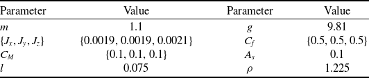
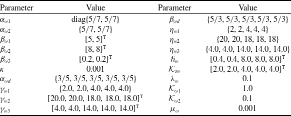
. The uniform dynamic parameters of a single quadrotor are listed in Table 1. Parameters of FTSO, FT-ESO and nonlinear control law are kept identical in all simulations, as shown in Table 2.
The inherent attribute parameters of a quadrotor.

Table 1 Long description
The table presents the inherent attribute parameters of a quadrotor. It consists of two columns labeled Parameter and Value, and eight rows. The parameters include mass, moments of inertia, force coefficients, moment coefficients, area, arm length, and air density. The values for these parameters are provided in the table. For example, the mass is 1.1 kilograms, the moments of inertia are 0.0019, 0.0019, and 0.0021 kilogram meters squared, and the force coefficients are 0.5, 0.5, and 0.5. The moment coefficients are 0.1, 0.1, and 0.1, the area is 0.1 square meters, the arm length is 0.075 meters, and the air density is 1.225 kilograms per cubic meter.
Parameters of FTSO, FT-ESO and ST-SMC law (
 $\omega =\{x,y,\phi ,\theta ,\psi \}$
).

Table 2 Long description
A table with two columns and twenty rows comparing parameters of FTSO, FT-ESO, and ST-SMC law for quadrotor control. The table lists parameters such as alpha, beta, eta, h, kappa, K, alpha d, lambda, gamma, K omega, and mu with their corresponding values. The values include matrices, vectors, and scalars. Row 1: alpha omega 1, diag 5/7, 5/7. Row 2: alpha omega 2, 5/7, 5/7. Row 3: beta omega 1, 5, 5 T. Row 4: beta omega 2, 8, 8 T. Row 5: beta omega 3, 0.2, 0.2 T. Row 6: kappa, 0.001. Row 7: alpha omega d, 3/5, 3/5, 3/5, 3/5, 3/5. Row 8: beta omega d, 5/3, 5/3, 5/3, 5/3, 5/3. Row 9: eta omega 1, 2, 2, 4, 4, 4. Row 10: eta omega 2, 20, 20, 18, 18, 18. Row 11: eta omega 3, 4.0, 4.0, 14.0, 14.0, 14.0. Row 12: h omega, 0.4, 0.4, 8.0, 8.0, 8.0 T. Row 13: K s omega, 2.0, 2.0, 4.0, 4.0, 4.0 T. Row 14: lambda omega, 0.1. Row 15: gamma omega 1, 2.0, 2.0, 4.0, 4.0, 4.0. Row 16: gamma omega 2, 20.0, 20.0, 18.0, 18.0, 18.0 T. Row 17: gamma omega 3, 4.0, 4.0, 14.0, 14.0, 14.0 T. Row 18: K omega 1, 1.0. Row 19: K omega 2, 0.1. Row 20: mu omega, 0.001.
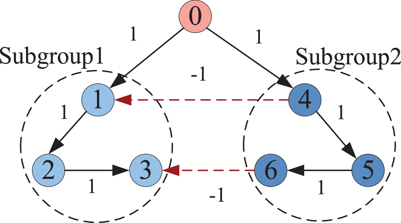
Example 1 (rotating radial formation). This example adopts a dynamic rotating radial formation. The formation takes the virtual leader as the centre, and the three followers are distributed radially on concentric circles with different radii. The communication topology is shown in Figure 2. And the adjacency (
 $\mathcal{A}$
), Laplacian (
 $\mathcal{L}$
) and pinning (
 $\mathcal{B}$
) matrices are as follows:
Communication topology of quadrotors in Example 1.

Figure 2 Long description
The diagram depicts the communication topology of quadrotors in formation, with nodes labeled 0 through 6. Node 0 is at the top, connected to nodes 1 and 4 with directed edges labeled 1. Nodes 1, 2, and 3 form Subgroup 1, with directed edges labeled 1 connecting them in a loop. Nodes 4, 5, and 6 form Subgroup 2, also connected in a loop with directed edges labeled 1. Dashed red lines with arrows connect nodes 1 to 4 and node 3 to 6, labeled -1, indicating inter-subgroup communication links.
 \begin{align*} A&=\left(\begin{array}{cccccc} 0 &\quad 0 &\quad\quad 0 &\quad -1 &\quad 0 &\quad 0\\ 1 &\quad 0 &\quad 0 &\quad 0 &\quad 0 &\quad 0\\ 0 &\quad 1 &\quad 0 &\quad 0 &\quad 0 &\quad -1\\ 0 &\quad 0 &\quad 0 &\quad 0 &\quad 0 &\quad 0\\ 0 &\quad 0 &\quad 0 &\quad 1 &\quad 0 &\quad 0\\ 0 &\quad 0 &\quad 0 &\quad 0 &\quad 1 &\quad 0 \end{array}\right),L=\left(\begin{array}{cccccc} 2 &\quad 0 &\quad 0 &\quad 1 &\quad 0 &\quad 0\\ -1 &\quad 1 &\quad 0 &\quad 0 &\quad 0 &\quad 0\\ 0 &\quad -1 &\quad 2 &\quad 0 &\quad 0 &\quad 1\\ 0 &\quad 0 &\quad 0 &\quad 1 &\quad 0 &\quad 0\\ 0 &\quad 0 &\quad 0 &\quad -1 &\quad 1 &\quad 0\\ 0 &\quad 0 &\quad 0 &\quad 0 &\quad -1 &\quad 1 \end{array}\right),\\[3pt] \nonumber B&=diag\left(1,0,0,1,0,0\right). \end{align*}
The movement path of the virtual leader is
 \begin{equation*} p_{0}=\left[\begin{array}{lll} 6\sin \left(0.05t\right) & 6\cos \left(0.05t\right) & 1 \end{array}\right]^{T}. \end{equation*}
Formation offsets are set
 \begin{equation*} \begin{cases} o_{1}=[\begin{array}{lll} 1.0\cos (0.1\pi +0.05t) & 1.0\sin (0.1\pi +0.05t) & 0 \end{array}]^{T}\\[3pt] o_{2}=[\begin{array}{lll} 2.0\cos (0.1\pi +0.05t) & 2.0\sin (0.1\pi +0.05t) & 0 \end{array}]^{T}\\[3pt] o_{3}=[\begin{array}{lll} 3.0\cos (0.1\pi +0.05t) & 3.0\sin (0.1\pi +0.05t) & 0 \end{array}]^{T}. \end{cases} \end{equation*}
Besides,
 $o_{4}=o_{1},o_{5}=o_{2},o_{6}=o_{3}$
. The initial states are chosen arbitrarily. The external wind disturbance in Experiment 1 is composed of basic wind, gust wind and gradient wind, and the specific setting is as follows: basic wind exists all the time, with a magnitude of
 $k_{wc}=[\!-6,-8,0]^{T}$
m/s
 $^{2}$
; from t = 15 s to t = 25 s, a gust wind is superimposed, with a maximum wind speed of 10 m/s and a direction vector of
 $\mathbf{d}_{\text{gust},\mathrm{dir}}=[0.1,0.9,0]^{T}$
; from t = 50 s, a gradient wind is superimposed, with a maximum wind speed of 10 m/s and the same direction vector as the gust wind, the rise time of the gradient wind is 5 s, and the holding time is 10 s.
The simulation results are shown in Figure 3. Firstly, Figure 3(a) and (b) depicts the estimated desired states in the formation configuration, while Figure 3(c) and (d) presents the corresponding state estimation errors, verifying the accurate estimation performance of the designed FTSOs. Secondly, the tracking performance of both the position and attitude subsystems under wind field disturbances is illustrated in Figure 3(e)–(g), demonstrating robust control characteristics of the adopted method. Additionally, the formation flight patterns are visualised in Figure 3(h), where the XOY plane trajectories clearly present two distinct subgroups: one maintaining formation with the virtual leader’s reference state, and the other forming a mirror configuration relative to the leader. Furthermore, the control inputs are presented in Figure 3(i). Finally, the wind disturbance compensation analysis in Figure 3(j)–(n) provides critical insights, demonstrating the effective estimation and compensation of wind-induced disturbances by the FT-ESOs for both position and attitude systems.
Simulation results in Example 1. (a) Estimated desired position (X- and Y-). (b) Estimated desired velocity (X- and Y-). (c) Position estimation errors (X- and Y-). (d) Velocity estimation errors (X- and Y-). (e) Position tracking errors (X- and Y-). (f) Velocity tracking errors (X- and Y-). (g) Attitude tracking errors. (h) Trajectories in the XOY plane. (i) Control inputs. (j) Disturbance estimations for the position subsystem (X-). (k) Disturbance estimations for the position subsystem (Y-). (l) Disturbance estimations for the position subsystem (Roll-). (m) Disturbance estimations for the position subsystem (Pitch-). (n) Disturbance estimations for the position subsystem (Yaw-).

Figure 3 Long description
The image contains multiple graphs depicting simulation results in Example 1. These graphs include estimated desired position in the X and Y directions, estimated desired velocity in the X and Y directions, position estimation errors in the X and Y directions, velocity estimation errors in the X and Y directions, position tracking errors in the X and Y directions, velocity tracking errors in the X and Y directions, attitude tracking errors, trajectories in the XOY plane, control inputs, and disturbance estimations for the position subsystem in the X, Y, Roll, Pitch, and Yaw directions. Each graph provides detailed insights into the performance and behavior of quadrotor systems under various conditions. All values are approximated.
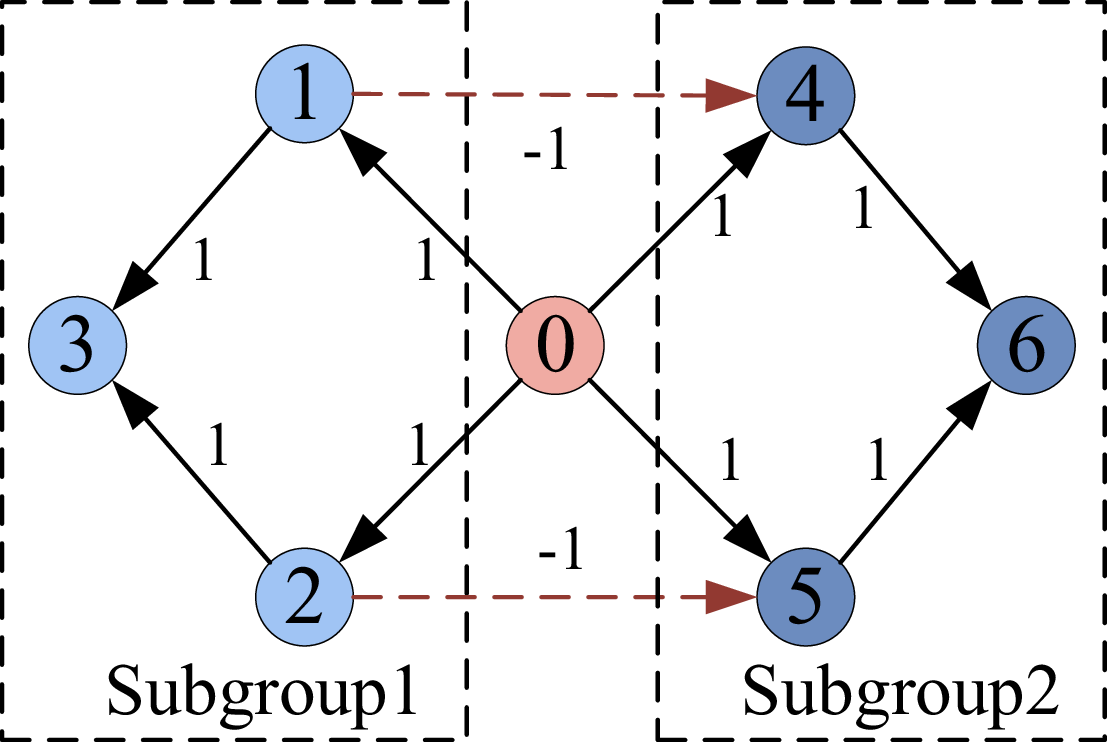
Example 2 (triangular formation). To validate the generality and robustness of the proposed method, simulation experiments are conducted under distinct communication topologies, formation configurations and disturbance conditions. A static equilateral triangular formation is employed, where three followers are symmetrically distributed around the virtual leader, forming a standard equilateral triangle with the leader at its centre. The communication topology among quadrotors is illustrated in Figure 4, with the adjacency (
 $\mathcal{A}$
), Laplacian (
 $\mathcal{L}$
) and pinning (
 $\mathcal{B}$
) matrices given as follows:
 \begin{align*} A&=\left(\begin{array}{cccccc} 0 &\quad 0 &\quad 0 &\quad 0 &\quad 0 &\quad 0\\ 0 &\quad 0 &\quad 0 &\quad 0 &\quad 0 &\quad 0\\ 1 &\quad 1 &\quad 0 &\quad 0 &\quad 0 &\quad 0\\ -1 &\quad 0 &\quad 0 &\quad 0 &\quad 0 &\quad 0\\ 0 &\quad -1 &\quad 0 &\quad 1 &\quad 0 &\quad 0\\ 0 &\quad 0 &\quad 0 &\quad 1 &\quad 1 &\quad 0 \end{array}\right),L=\left(\begin{array}{cccccc} 1 &\quad 0 &\quad 0 &\quad 0 &\quad 0 &\quad 0\\ 0 &\quad 1 &\quad 0 &\quad 0 &\quad 0 &\quad 0\\ -1 &\quad -1 &\quad 2 &\quad 0 &\quad 0 &\quad 0\\ 1 &\quad 0 &\quad 0 &\quad 2 &\quad 0 &\quad 0\\ 0 &\quad 1 &\quad 0 &\quad 0 &\quad 2 &\quad 0\\ 0 &\quad 0 &\quad 0 &\quad -1 &\quad -1 &\quad 2 \end{array}\right),\\[3pt] B&=diag\left(1,1,0,1,1,0\right). \end{align*}
The movement path of the virtual leader is
 \begin{equation*} p_{0}=\left[3\cos \left(0.1t\right)3\sin \left(0.1t\right)1\right]^{T}. \end{equation*}
Formation offsets are as follows:
 \begin{align*} \begin{cases} o_{1}=\left[\begin{array}{lll} 2.0\cos \left(0.1t+\pi /2\right) & 2.0\sin \left(0.1t+\pi /2\right) & 0 \end{array}\right]^{T}\\[3pt] o_{2}=\left[\begin{array}{lll} 2.0\cos \left(0.1t+\pi /2+2\pi /3\right) & 2.0\sin \left(0.1t+\pi /2+2\pi /3\right) & 0 \end{array}\right]^{T}\\[3pt] o_{3}=\left[\begin{array}{lll} 2.0\cos \left(0.1t+\pi /2+4\pi /3\right) & 2.0\sin \left(0.1t+\pi /2+4\pi /3\right) & 0 \end{array}\right]^{T}. \end{cases} \end{align*}
Besides,
 $o_{4}=o_{1},o_{5}=o_{2},o_{6}=o_{3}$
. The initial states are chosen arbitrarily. The parameters of external wind disturbance in Experiment 2 are as follows: Starting from t = 10 s, quadrotors are affected by a basic wind with a magnitude of
 $k_{wc}=[\!-6,-8,0]^{T}$
m/s
 $^{2}$
; at t = 10 s, a gradient wind is superimposed, with a maximum wind speed of 8 m/s and a direction vector of
 $\mathbf{d}_{\text{grad},\mathrm{dir}}=[0.2,0.8,0.0]^{T}$
, the rise time of the gradient wind is 3 s and the holding time is 7 s; at t = 30 s, a gust wind is superimposed, with a maximum wind speed of 10 m/s and the same direction vector as the gradient wind and the duration of the gust wind is 15 s.
Simulation results are presented in Figure 5. Figure 5(a) and (b) presents the estimated desired states of quadrotors within the formation configuration, while Figure 5(c) and (d) displays the associated state estimation errors, validating the precise estimation performance of the designed FTSOs. Tracking performance of the position and attitude subsystems under wind disturbances is shown in Figure 5(e)–(g), manifesting the robust control properties of the proposed scheme. Formation flight patterns are visualised in Figure 5(h), where two symmetric triangular configurations are clearly exhibited. Control input profiles are presented in Figure 5(i). Wind disturbance compensation analysis in Figure 5(j)–(n) offers key insights, verifying the effective estimation and rejection of wind-induced disturbances via FT-ESOs for both position and attitude loops.
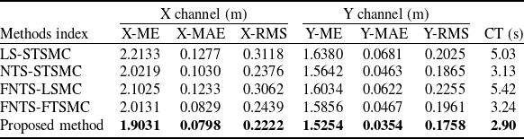
Performance comparison of tracking errors with different methods.

Table 3 Long description
A table comparing tracking errors of different methods in X and Y channels. The table has six columns: X-ME, X-MAE, X-RMS, Y-ME, Y-MAE, Y-RMS, and CT (s), and five rows representing different methods: LS-STSMC, NTS-STSMC, FNTS-LSMC, FNTS-FTSMC, and Proposed method. Each row lists the tracking errors and computation time for the respective method. The Proposed method shows the lowest tracking errors and computation time, indicating superior performance.
Communication topology among quadrotors in Example 2.

Figure 4 Long description
The diagram illustrates the communication topology among quadrotors in Example 2. It is divided into two subgroups, labeled Subgroup 1 and Subgroup 2. Each subgroup contains four nodes labeled with numbers: Subgroup 1 has nodes 1, 2, 3, and 0, while Subgroup 2 has nodes 4, 5, 6, and 0. Nodes are connected by directional arrows indicating the flow of communication. Within Subgroup 1, node 1 connects to nodes 3 and 2, node 3 connects to node 2, and node 0 connects to nodes 1, 2, and 3. In Subgroup 2, node 4 connects to nodes 0 and 6, node 6 connects to node 5, and node 0 connects to nodes 4, 5, and 6. The nodes in Subgroup 1 and Subgroup 2 are connected by dashed arrows labeled with -1, indicating a weaker or different type of connection. The diagram highlights the complex interactions and communication paths among the quadrotors, emphasizing the importance of robust communication topology in formation control.
Simulation results in Example 2. (a) Estimated desired position (X- and Y-). (b) Estimated desired velocity (X- and Y-). (c) Position estimation errors (X- and Y-). (d) Velocity estimation errors (X- and Y-). (e) Position tracking errors (X- and Y-). (f) Velocity tracking errors (X- and Y-). (g) Attitude tracking errors. (h) Trajectories in the XOY plane. (i) Control inputs. (j) Disturbance estimations for the position subsystem (X-). (k) Disturbance estimations for the position subsystem (Y-). (l) Disturbance estimations for the position subsystem (Roll-). (m) Disturbance estimations for the position subsystem (Pitch-). (n) Disturbance estimations for the position subsystem (Yaw-).

Figure 5 Long description
The image contains multiple graphs depicting simulation results in Example 2. The first set of graphs (a) shows the estimated desired position in the X and Y directions over time. The second set (b) illustrates the estimated desired velocity in the X and Y directions over time. The third set (c) presents the position estimation errors in the X and Y directions over time. The fourth set (d) displays the velocity estimation errors in the X and Y directions over time. The fifth set (e) shows the position tracking errors in the X and Y directions over time. The sixth set (f) illustrates the velocity tracking errors in the X and Y directions over time. The seventh set (g) presents the attitude tracking errors over time. The eighth graph (h) depicts the trajectories in the XOY plane. The ninth set (i) shows the control inputs over time. The tenth set (j) illustrates the disturbance estimations for the position subsystem in the X direction over time. The eleventh set (k) presents the disturbance estimations for the position subsystem in the Y direction over time. The twelfth set (l) displays the disturbance estimations for the position subsystem in the roll direction over time. The thirteenth set (m) shows the disturbance estimations for the position subsystem in the pitch direction over time. The fourteenth set (n) illustrates the disturbance estimations for the position subsystem in the yaw direction over time. All values are approximated.
To validate the superior performance of the proposed method, we consider Example 1 as a benchmark case and conduct comparative simulations using different sliding mode control methods, which are realised by modifying the sliding surface and adjusting the reaching law. Specifically, the employed control strategies include: ST-SMC with a linear sliding surface (LS-STSMC), ST-SMC with a nonsingular terminal sliding surface (NTS-STSMC), linear SMC integrated with a fast non-singular terminal sliding surface (FNTS-LSMC), finite-time SMC based on a fast non-singular terminal sliding surface (FNTS-FTSMC) and the proposed method. The comparison of performance metrics includes maximum error (ME), mean absolute error (MAE), root mean square error (RMSE) and convergence time (CT). Comparative results are illustrated in Figure 6 and Table 3. In contrast to the aforementioned control strategies, the proposed approach delivers enhanced formation precision, swifter convergence rate, more favourable overall control performance and greater robustness to external disturbances.
Performance comparison of tracking errors under different methods. (a) X-channel. (b) Y-channel.

Figure 6 Long description
The line graph compares tracking errors under different methods for X and Y channels. The X-channel graph (a) shows tracking errors with three data lines labeled ME, MAE, and RMS. The ME line starts at 2.2133 and decreases to 1.9031. The MAE line starts at 0.3118 and fluctuates slightly, ending at 0.2222. The RMS line starts at 0.1277 and decreases to 0.0798. The Y-channel graph (b) also shows tracking errors with three data lines labeled ME, MAE, and RMS. The ME line starts at 1.6380 and slightly decreases to 1.5254. The MAE line starts at 0.2025 and fluctuates slightly, ending at 0.1758. The RMS line starts at 0.0681 and decreases to 0.0354. All values are approximated.
5.0 Conclusion
This study addresses the BTVFC problem for multiple quadrotors in wind-disturbed environments, proposing a finite-time cooperative control method within a hierarchical framework. First, a comprehensive 6-DoF dynamic model is established, explicitly integrating wind disturbance effects. An FT-ESO is then given to satisfy accurate real-time estimation of wind-induced disturbances. The position control loop combines an FTSO for precise formation state estimation with an ST-SMC scheme, ensuring robust position tracking. Correspondingly, the attitude control subsystem uses nonlinear decoupling to convert position commands into valid attitude references, then applies the ST-SMC scheme to guarantee finite-time attitude stabilisation. Lyapunov stability analysis proves the closed-loop system achieves finite-time convergence. Numerical simulations under full 6-DoF scenarios verify the proposed framework’s effectiveness and superiority. Future research will further improve the proposed control framework by conducting physical experiments and handling complex transient winds.
Competing interests
The institutions of all the authors are the College of Intelligence Science and Technology, National University of Defense Technology, Changsha, Hunan Province, China. We declare that we do not have any commercial or associative interest that represents a conflict of interest in connection with the work submitted.

 ω={x,y,ϕ,θ,ψ}