I. INTRODUCTION
Graphene is a two-dimensional one atom thick crystalline form of carbon which is the most abundant and widely studied material for use in the electronics industry. Reference Sadeghi, Sangtarash and Lambert1 One promising route is to take advantage of reduced lattice thermal conductivity in low dimensional materials which can be obtained by nanostructuring it to create nanoribbons. Reference Sadeghi, Sangtarash and Lambert1–Reference Nika and Balandin5 This decrease could be further engineered in porous nanoribbons, since phonon thermal conductivity is reduced in nanoporous semiconductors. Reference Mingo and Broido6 The parameter used to evaluate the thermoelectric performance of a material is dimensionless figure of merit ZT which is expressed as ZT = S 2 GT/k, where S is the Seebeck coefficient, G is electrical conductivity, T is temperature, and k is thermal conductivity. Here k is the summation of electron thermal conductivity (k e) and lattice or phonon thermal conductivity (k ph). The quantity S 2 G is called the power factor (PF) which is the ability of a device to handle voltage and current. Thus a large ZT requires high S, high G, and low thermal conductivity. However these factors are correlated and thus it requires a delicate optimization to yield higher ZT values. Reference Qi, Wang, Zhang, Yang and Wang7
Researchers have theoretically investigated many different methods of modulating the geometry of 1D nanostructures including: rough surface, Reference Liu and Chen8,Reference Sandhu, Seong and Sinha9 heterostructures, Reference Zhang, Yu, Wang and Li10 helical nanoconfiguration, Reference Varshney, Roy, Dudis, Lee and Farmer11 and double bend NWs. Reference Zhou and Yang12 Several theoretical works have been carried out to investigate the performance of graphene and graphene nanoribbons (GNRs) as thermoelectric materials. Yang et al. Reference Yang, Chen, Agosta, Xie, Zhong and Rubio13 have theoretically proposed a hybrid structure of graphene-hexagonal boron nitride nanoribbons whose ZT is enhanced by 1.5–3 times due to the presence of interface scattering. Very recently, Hossain et al. Reference Hossain, Al-Dirini, Hossain and Skafidas14 have introduced rectangular nanopores in the nanoribbon and tuned the pore to its optimal dimension which results in superior ZT which is six times higher than pristine GNRs. Their device of length 8.2 nm was shown to possess maximum ZT of 0.61 when the number of atoms in the side channels was reduced to 4. Also nanopore arrays along with the use of heavy adatoms have been fabricated in long zigzag and chiral GNRs by various experiments done by Chang et al. Reference Chang and Nikolic15,Reference Chang, Bahramy, Nagaosa and Nikolić16 Their chiral device was found to reach ZT of around 3 which could further be optimized by optimizing pore diameter and the distance between the pores. By tuning the distance between the pores for a random pore diameter in case of zigzag GNRs, they were able to achieve ZT of around 4 at a temperature of 300 K. Haskins et al. Reference Haskins, Kinaci, Sevik, Sevincli, Cuniberti and Cagin17 showed theoretically that thermal and electrical properties of graphene can be controlled independently through defect engineering. They simulated GNR structures to study the effect of randomly distributed single and double vacancies, Stone–Wales defects and different edge roughness. Their structure of length 125 μm with roughness of 1.98 Ǻ was shown to exhibit higher ZT values of around 0.41 in magnitude. Ouyang et al. Reference Yijian and Jing18 have studied the thermoelectric properties of pristine GNRs which behave as inefficient thermoelectric material with quite low figure of merit. Quantum effects resulting in Fano resonances have been investigated in hexagonal graphene ring by Bretin et al. Reference Saiz-Bretin, Malyshev, Orellana and Adame19 They concluded that higher values of ZT can be achieved by tuning the chemical potential and the side gate voltage. Mazzamuto et al. Reference Mazzamuto, Nguyen, Apertet, Chassat, Saint-Martin and Dollfus20 have studied the mixed edged GNRs where resonant tunneling transport occurs and achieves ZT values of above unity. Also Liang et al. Reference Liang, Cruz-Silva, Girao and Meunier21 studied graphene nanowiggles GNWs employing resonant tunneling effect and found the enhanced values of ZT. Their devices were predicted to achieve a ZT of 0.79 at room temperature. On the other hand, Sevincli et al. Reference Sevincli and Cuniberti22 have predicted that by introducing edge roughness in zigzag GNRS, a ZT of 4 can be achieved. Although the above mentioned work is theoretical with no experimental validation other groups have experimentally investigated the thermopower of graphene. Reference Hossain, Al-Dirini, Hossain and Skafidas14,Reference Checkelsky and Ong23–Reference Wei, Bao, Pu, Lau and Shi25
The proposed device is an armchair graphene nanoribbon based structure. Thermal conductivity is less in case of armchair GNRs when compared with ZGNRs of same dimensions. Reference Hossain, Al-Dirini, Hossain and Skafidas14 Also they show pore dimension dependent transport parameters accounting for their selection. Graphene has been the center stage of research recently. Its synthesis techniques Reference Mazzamuto, Nguyen, Apertet, Caer, Chassat, Saint-Martin and Dollfus26–Reference Mazzamuto, Saint-Martin, Nguyen, Chassat and Dollfus28 such as electron beam lithography, Reference Han, Ozyilmaz, Zhang and Kim29 the use of nanowires as etch mask Reference Bai, Duan and Huang30 and molecular templating have greatly advanced, allowing precise fabrication of GNRs. Reference Hossain, Al-Dirini, Hossain and Skafidas14 However, drilling pores in GNRs with atomistic precision is a challenging task. Nevertheless, techniques like transmission electron microscopy Reference Wei, Qiang, Meng-Qiang and Kuhn31,Reference Tapaszto, Dobrik, Lambin and Biro32 and helium ion beam milling Reference Wei, Qiang, Meng-Qiang and Kuhn31,Reference Kalhor, Boden and Mizuta33,Reference Abbas, Liu, Liu, Zhang, Liu, Ohlberg, Wu and Zhou34 can also be used to drill pores in GNRs with precise control. This supports the realization of the device proposed in this paper.
II. MODELING AND COMPUTATIONAL METHODS
In this paper, we propose a new thermoelectric device structure based on armchair GNRs embedded with circular and triangular pores of various dimensions. Also the dependence on the length of the ribbon is observed. By varying the dimension of the pore, we can attain superior electrical conductivity, while the introduction of the pore greatly reduces the thermal conductivity. These two factors lead to enhanced thermoelectric performance.
The thermoelectric performance of a material is measured in terms of dimensionless figure of merit:
 $$ZT = {{{S^2}GT} \over {{k_{\rm{e}}} + {k_{{\rm{ph}}}}}}\quad ,$$
where S is Seebeck coefficient, G is electrical conductance, and T is temperature. The thermal conductance comprises of two parts, thermal electron conductance k e, and thermal phonon conductance k ph. The thermoelectric properties of a nanosystem for a linear response regime can be determined from the definition of the electrical and thermal currents Reference Hossain, Al-Dirini, Hossain and Skafidas14 :
 $${I_E} = {{2e} \over h}\int {{\rm{d}}ET\left( E \right)\left[ \,{{f_{\rm{L}}}(E) - {f_{\rm{R}}}\left( E \right)} \right]} \quad ,$$
 $${I_{\rm{Q}}} = {{2e} \over h}\int {{\rm{d}}ET(E)\left[ \,{{f_{\rm{L}}}\left( E \right) - {f_{\rm{R}}}\left( E \right)} \right]{\rm{\ }}\left( {E - \mu } \right)} \quad ,$$
where e is the carrier charge, T(E) is the transmission coefficient of the device, f L and f R are the distribution function of left and right reservoirs, and μL and μR being the chemical potentials. Thermoelectric transport properties can be obtained by using Taylor expansion of Eqs. (2) and (3) as Reference Zhang, Yu, Wang and Li10 :
 $$G = {\left. {{I \over {\Delta V\Delta }}} \right|_{\Delta T = 0}} = {\rm{\ }}{q^2}{L_0}\quad ,$$
 $$S = - {\left. {{{\Delta V} \over {\Delta T}}} \right|_{I = 0}} = {{{L_1}} \over {qT{L_0}}}{\rm{\ }}\quad {\rm{,}}$$
 $${k_{\rm{e}}} = {\left. {{{{I_{\rm{Q}}}} \over {\Delta T}}} \right|_{IE = 0}} = {{{{{L_2} - L_1^2} \mathord{\left/ {\vphantom {{{L_2} - L_1^2} {{L_0}}}} \right. \kern-\nulldelimiterspace} {{L_0}}}} \over T}{\rm{\ }}\quad {\rm{,}}$$
where
 $${L_n} = {2 \over h}\int {{\rm{d}}ET\left( E \right)\left( { - {{\partial f} \over {\partial E}}} \right){{\left( {E - \mu } \right)}^n}} \quad .$$
The formalism used here is from the work of Esfarjani et al. Reference Esfarjani, Zebarjadi and Kawazoe35 Here, ∂f/∂E is the derivative of the Fermi function [f = 1 + exp((E − μ)/k B T)−1]. Reference Sadeghi, Sangtarash and Lambert36 The Hamiltonian H and overlap S ov matrices calculated from extended Huckel technique Reference Kienle, Cerda and Ghosh37,Reference Landauer38 with Hoffman basis are then solved using nonequilibrium Green function (NEGF) to yield the transmission co-efficient T(E) for electrons of energy E passing from the source to the drain via the relation Reference Sadeghi, Sangtarash and Lambert1,Reference Hossain, Al-Dirini, Hossain and Skafidas14 :
 $$T\left( E \right) = {\rm{Trace}}\right[ {\Gamma _{\rm{R}}}\left( E \right){G^{\rm{R}}}\left( E \right){\Gamma _{\rm{L}}}\left( E \right){G^{{\rm{R }}}}\left( E \right)]\quad .$$
In this expression ΓL,R(E) = i(ΣL,R(E) − ΣL,R†(E)) describes the level broadening due to the coupling between left and right electrodes and the central scattering region, ΣL,R(E) are the retarded self-energies associated with this coupling and G R = (ES − H − ΣL − ΣR)−1 is the retarded Green function. The mesh points in real space calculation were defined as 1 × 1 × 100 k points, mesh cut-off at 10 Hartree and the temperature was set at 300 K.
To calculate the phonon thermal conductance we used the Landauer approach Reference Landauer38 :
 $${k_{{\rm{ph}}}} = {{{h^2}} \over {2\pi {k_{\rm{B}}}{T^2}}}\int {{\rm{d}}\omega {\omega ^2}{T_{{\rm{ph}}}}(\omega )\left( {{{\partial n} \over {\partial \omega }}} \right)} \quad .$$
The phonon transmission T ph(ω) is calculated in a similar technique to the one used for calculating the electrical conductance, by substituting H by a force constant matrix K, and substituting S ov by a diagonal matrix of atomic mass M. The term ∂n/∂ω is the derivative of the Bose–Einstein distribution for phonons. To calculate the force constant matrix for phonons, empirical Tersoff potential Tersoff_CH_2005 was used.
Both simulations are performed in the Virtual NanoLab-Atomistix Toolkit (ATK) software package. Reference Stokbro, Peterson, Smidstrup, Blom, Ipsen and Kaasbjerg39 Each structure is optimized before transport calculations with its atom coordinates relaxed so that the forces on individual atoms are minimized to be smaller than 0.01 eV/Ǻ. Here, electron–phonon interactions are neglected since we were working on independent electrons and phonons. This can be justified based on the work by Chen et al. Reference Chen, Jang, Xiao, Ishigami and Fuhrer40 where they have experimentally showed that the mean free path for electron-acoustic phonon scattering in graphene is greater than 2 µm, which is much larger than our device dimensions. Reference Zhang, Yu, Wang and Li10
III. RESULTS AND DISCUSSIONS
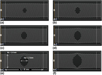
The width W r and length L r of the ribbon is kept constant at 2.4 nm (21 atoms wide) by 8 nm as shown in Fig. 1 while the pore dimensions are varied to achieve superior performance. In the later section, the effect of the change in length of the ribbon is also studied.
Geometrical optimized structure of the graphene nanoribbon with circular nanopore thermoelectric device with pore diameter (a) 0.78 nm, (b) 0.98 nm, (c) 1.23 nm, (d) 1.48 nm, (e) 1.72 nm, and (f) 1.97 nm.

A. Circular pore
The atomistic model of our proposed armchair graphene ribbon structures with circular shaped pores is shown in Fig. 1.
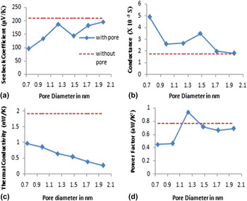
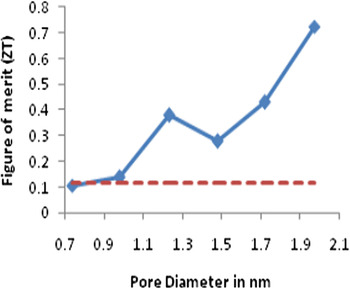
As it elucidates, each pore has its own associated edge terminations with two channels on both sides of the nanoribbon whose width is dependent on the diameter of the pore. Based on the configuration described above, there are two important dimensions that need to be optimized for enhanced thermoelectric performance; the diameter of the pore D p and the associated edge structure of the atoms. Here the various diameters of the nanopore used are 0.74, 0.98, 1.23, 1.48, 1.72, and 1.97 nm respectively which have their own edge terminations. It is hereby observed that the pore with diameter of 1.97 nm as shown in Fig. 1(f) provides the best result amongst all followed by 1.72 nm. The reason is the decrease in thermal conductivity with the increase in the pore diameter. Since the Seebeck coefficient and conductance are interrelated with one another, a decrease in one of them is compensated by the other to provide superior performance as shown in the Figs. 2(a) and 2(b). Although it has the highest ZT being observed here, the only limitation for its use is stability. Hence it can perform exceptionally well where stability is a secondary concern. While all the other structures perform well as far as stability issues are concerned. Reference PengTao, Xiang, Sai, Zhen and PanWen41–Reference Vanin, Gath, Thygesen and Jacobsen43 The structure with pore diameter of 1.72 nm as shown in Fig. 1(e) provides the best performance along with stability concerns with a little compromise in ZT as compared to pore diameter of 1.97 nm.
(a) Seebeck coefficient, (b) conductance, (c) thermal conductivity, and (d) power factor for circular nanopore GNRs plotted against the diameter of the pore. The dashed lines indicate the respective values for GNR with no pore.

The results obtained for the various structures are shown in Figs. 2 and 3. The variation in values of the parameters S, G, and k ph are plotted w.r.t dimension of the nanopore. The basic values of GNRs without nanopore are depicted by dotted line while the variable values for GNRs with pores are plotted by bold line. For S, it is always above than that of the GNR with a pore while is always lesser than that of G with a pore. However, the thermal conductivity is reduced significantly upon the introduction of the pore. These parameters in turn lead to enhancement of the overall figure of merit as shown in Fig. 3.
Figure of merit for circular nanopore GNRs plotted against the diameter of pore. The dashed lines indicate ZT for GNR with no pore.

B. Triangular pore
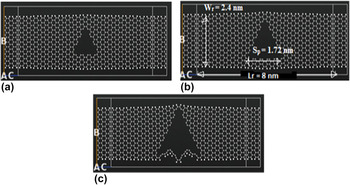
The atomistic model of our proposed armchair graphene ribbon structures with triangular shaped pores is shown in Fig. 4. The symmetrical orientation of the triangular pore embeds an equilateral triangle with each side of the triangle S p being 1.16h where h is the height of the triangle (in nm) such that the minimum number of atoms below and above the triangle corner edges should be same. Based on the symmetry of the triangle, three different sizes corresponding to sides of 1.14, 1.72, and 2.29 nm as shown in Fig. 4 are hereby being considered.
Geometrical optimized structure of the graphene nanoribbon with triangular nanopore thermoelectric device with triangular side of (a) 1.14 nm, (b) 1.72 nm, and (c) 2.29 nm.

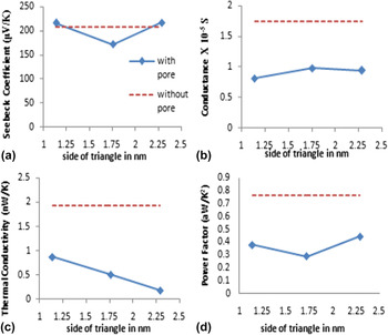
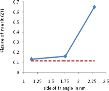
It is hereby observed that the triangular pore with side of 2.29 nm [Fig. 4(c)] provides the best result amongst all followed by 1.72 nm. As it is observed in Fig. 5(d), where the dotted straight line denotes GNR without pore, the power factor is rather decreasing with the introduction of triangular pore, therefore it is simply the decrease in thermal conductivity that leads to better performance. There is a steep increase in performance for size larger than 1.72 nm (Fig. 6) as at this point, the Seebeck coefficient and conductance show an increasing trend leading to improvement in power factor and hence ZT.
(a) Seebeck coefficient, (b) conductance, (c) thermal conductance, and (d) power factor for triangular nanopore GNRs plotted against the side of the equilateral triangular pore.

Figure of merit for triangular nanopore GNRs plotted against the side of the equilateral triangular pore.

It is observed that the conductance pattern is not similar for two geometrical patterns. The conductance decreases substantially upon the introduction of the pore of triangular shape as opposed to the circular one.
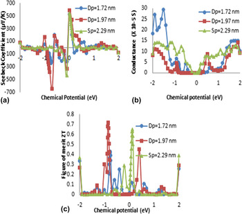
To further understand the properties of GNRs, transport coefficients are investigated. The thermoelectric (TE) transport coefficients are plotted as a function of chemical potential, for those dimensions which are resulting in achieving maximum figure of merit i.e., circular diameter of 1.97 nm and 1.72 nm respectively and equilateral side of 2.29 nm in case of triangular pore. Within the rigid band model, chemical potential indicates the doping level (carrier concentration) which is achieved by introducing donor or acceptor onto the surface of graphene nanoribbon in case of a real device. An alternative is to use a third gate electrode which in practice costs energy. To determine the TE transport coefficients, i.e., electrical conductivity and Seebeck coefficient, we first calculate the transmission function T(E) (refer to method section). The dependence of S, G, and ZT with respect to chemical potential is shown in Fig. 7. This is done by first finding the value of chemical potential which results in maximum ZT value and then extracting S and G for this chemical potential.
Chemical potential dependent behavior of (a) Seebeck coefficient, (b) conductance, and (c) thermoelectric figure of merit. All calculations are done at 300 K.

The highest Seebeck coefficient obtained is −641.5 μV/K for circular diameter of 1.97 nm followed by 542.5 μV/K in triangular pore of 2.29 nm and 530.6 μV/K in case of circular pore of 1.72 nm. The highest conductance obtained is 29.31 (×10−5 S) for circular diameter of 1.72 nm followed by 14.2 (×10−5 S) in triangular pore of 2.29 nm and 14.08 (×10−5 S) in case of circular pore of 1.97 nm. The Seebeck coefficient arrives its maximum around μ ≈ k B T which is very close to the edge of the first conduction channel where the transmission function T(E) jumps from zero to finite value. As a result, there is a sharp increase in the electrical conductance. Reference Pan, Liu, Tan, Lv, Shi, Tang and Zheng44 The consistent values of S, G, and ZT for circular pore of D p = 1.97 nm and triangular pore of S p = 2.29 nm suggest that this device structure could be used for the applications overcoming variation in the size defects.
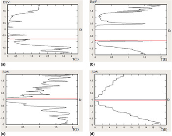
Figure 8 shows the transmission spectras Reference Kaur, Sawhney and Engles45 of these different device structures with energies of [−2.0, 2.0] eV. Since conductance depends on the overlap of the Fermi-window and the transmission spectra while Seebeck coefficient is dependent on the difference between the energy of conducting electron and chemical potential, Reference Hossain, Al-Dirini, Hossain and Skafidas14 there is a sharp compromise between the two and hence the shape of the transmission spectra needs to be optimally controlled which provides with a good compromise between Seebeck coefficient and conductance. By using the optimal pore dimensions, the shape of the transmission spectrum can be controlled to give the best performance.
Transmission spectrum for (a) circular pore of diameter 1.72 nm (b) circular pore of diameter 1.97 nm (c) triangular pore of side 2.29 nm, and (d) GNR-no pore. Here the straight bold line shows the chemical potential at which maximum ZT is achieved. It is at −0.78 eV, −0.86 eV, 0.12 eV, and −0.11 eV for (a), (b), (c), and (d) respectively.

C. Length dependence
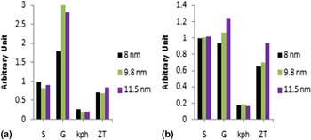
Here, we keep the size of the pore fixed for which the maximum ZT was achieved and then vary the length of the ribbon and conduct the similar analysis to evaluate performance. Three different lengths of 8, 9.8, and 11.5 nm are here considered in both the shapes. The values of S, G, k ph, and ZT for that position of μ which results in maximum ZT are then compared as shown in Fig. 9. The consistent values of S (217.5–220.9 μV/K) and k ph (0.17–0.19 nW/K) in case of triangular pore suggest an appealing application for overcoming variation in length defects.
Effect of variation in length of ribbon in (a) circular porous GNRs; (b) triangular porous GNRs. Value of Seebeck coefficient for 8 nm is normalized to 1 while for other lengths, it is normalized relative to 8 nm. G, k ph, and ZT are the actual values.

D. Temperature dependence
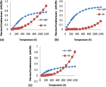
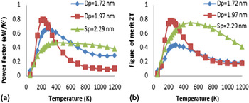
As the working of thermoelectric devices is based on the temperature, it is mandatory to observe its response to variable temperature. Since thermoelectric devices usually operate in a wide temperature range, we analyzed the effect of temperature on our devices. It is hereby observed that the phonon thermal conductivity increases with temperature as shown in Figs. 10(a)–10(c) which is in accordance with other methods used to model phonon thermal conductivity. Reference Chang and Nikolic15 Also the electrical thermal conductivity shows a similar trend. But owing to the relatively higher increase in power factor at low temperature levels of the range 0–300 K [Fig. 11(a)] and the presence of temperature in numerator of ZT, it increases with rise in temperature from 0 to 300 K (circular pores) and 0–500 K (triangular pores) and then begins to decrease for temperature till 800 K [Fig. 11(b)] although the slope is gradual in case of triangular pores. For higher temperature levels after 800 K, overall value of ZT remains almost stable. These calculations do not take into account the electron–phonon and electron–electron interactions which dominate at high temperatures.
Temperature dependent behavior of thermal conductivity due to phonons (k ph) and electrons (k e) for (a) circular pore of diameter 1.72 nm (b) circular pore of diameter 1.97 nm (c) triangular pore of side 2.29 nm.

Temperature dependent behavior of (a) power factor (b) thermoelectric figure of merit plotted for circular pore of diameter 1.72 nm, circular pore of diameter 1.97 nm and triangular pore of side 2.29 nm.

E. Comparison between circular and triangular pores
To investigate the shape dependent thermoelectric properties, we consider those cases of the pores in which the number of atoms to be deleted to fabricate the pore are almost same. Three such dimensions corresponding to:
-
(i) Pore diameter of 0.98 nm (34 atoms) compared with triangular side of 1.14 nm (36 atoms).
-
(ii) Pore diameter of 1.48 nm (70 atoms) compared with triangular side of 1.72 nm (70 atoms).
-
(iii) Pore diameter of 1.97 nm (118 atoms) compared with triangular side of 2.29 nm (114 atoms).
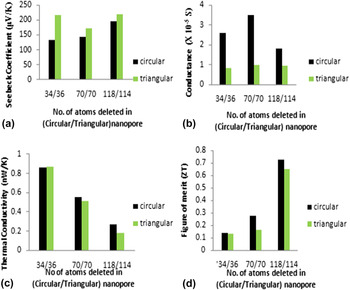
Here, the variation of the transport coefficients in various cases is observed and the values of S, G, k ph against the chemical position which results in maximum ZT are then extracted. Figure 12 shows the comparison between these parameters. Although the Seebeck coefficient and phonon thermal conductance shows little variation between circular and triangular shapes, it is the higher value of G in case of circular shaped pores which renders them better thermoelectric devices as compared to their triangular counterparts.
Comparison between circular and triangular shaped porous GNRs. (a) Seebeck coefficient, (b) conductance, (c) thermal conductance, and (d) figure of merit plotted for both shapes.

IV. CONCLUSION
In summary, we have analyzed the influence of different pore shapes and their dimensions on the thermoelectric performance of GNR-NP devices. In addition to the rectangular shape used by Hossain et al., our work extends their idea by contributing toward the effect of circular and triangular nanopores with different dimensions and further we have succeeded in achieving better figure of merit. Our analysis shows that the thermoelectric performance of the nanostructure is dependent on the shape of the pore and the associated edge terminations corresponding to the size of the pore. We can thus modify the transmission spectra by optimizing these parameters to achieve better thermoelectric performance. If stability issues are not of much concern, our device can offer figure of merit which is approximately 6 times higher than a GNR without a pore and 4 times higher even for stability applications. We have neglected the electron–phonon interaction to simplify model which might result in quantitative discrepancy from experimental values rather than any significant qualitative discrepancy since such simplifications are justifiable. Thus our study provides a route toward achieving better thermoelectric performance in GNRs by introducing nanopores and tuning their dimensions.