1. Introduction
Translation, a basic and important form of motion in robots, offers significant potential for generating novel motion patterns [Reference Song, Xian, Huo and Qi1]. In this paper, motion patterns refer to the finite motion patterns (full-cycle motion pattern) generated by robots [Reference Liu, Kong and Yu2–Reference Lin, Guo and Cheng6], including the number, type, and specific characteristics of each degree of freedom.
Till now, scholars have extensively investigated robots with various motion patterns, including serial robots [Reference Sun, Lian, Yang and Song7], parallel robots [Reference Wang, Kong and Yu8–Reference Zhang, Fang, Fang and Dai12], hybrid robots [Reference Dai and Wang13–Reference Feng, Chen, Dai and Gogu17], and others [Reference Qin, Dai and Gogu18–Reference Saglia, Tsagarakis, Dai and Caldwell26]. Dai [Reference Wang, Song and Dai27–Reference Li, Dai, Zhang and Jin30] has made significant contributions to the study of metamorphic and reconfigurable robots with screw theory, pioneering the field of reconfigurable robots and providing valuable guidance for robot design. A wealth of research has also focused on translational robots, such as single-DoF robots moving along fixed directions [Reference Gregorio31–Reference Zhang, Kang and Li34], two-DoF translational robots moving on planes [Reference Guo, Sun, Wang, Liu and Song35, Reference Yao, Gu, Haung, Wei and Dai36], and spatial three-DoF translational robots [Reference Chen, Liu, Dong, Zhang, Guo, Xiao and Chen37–Reference Kang, Lin, Feng and Li39]. Kong [Reference Kong40] has analyzed a 6R over-constrained spatial robot for circular translation and conducted kinematic analysis of the solution of a quadratic equation, giving scholars a new perspective on translations. Shen [Reference Wang, Li, Shen, You and Yang41, Reference Li, Zhu, Shen and Chablat42] has studied spatial single-loop parallel robots generating two translations and proposed a novel three-translation parallel robot. His researches enrich the variety of translational robots and provide valuable experience for topological design and kinematic analysis of parallel robots. Additionally, the existing researches have explored motion patterns involving translations on complex surfaces. For example, López-Custodio [Reference López-Custodio, Müller, Rico and Dai43–Reference López-Custodio, Müller, Kang and Dai45] proposes a synthesis for spatial single-degree-of-freedom closed-loop robots, synthesizing spatial curve motion generators with specific characteristics. By appropriately connecting this module with its mirrored module, the mechanism generates motion along a specific spatial curve, providing a theoretical foundation for studying robots that manufacture curves generated by the intersection of surfaces. Yang [Reference Yang and Li46] has studied the robots generating translations on circular surface, cylindrical surface, and conical surface. He uses finite screw theory for analytical representation and synthesizes closed-loop linkages that generate elliptical curves. Inspired by these existing works, this paper presents a general method for design and synthesis of closed-loop robots machining and manufacturing complex quadric surfaces, which can generate translations on all kinds of complex quadric surfaces.
Robots synthesized by the approach proposed in this paper have potential applications in machining and manufacturing of space curves and surfaces [Reference Selig and Paola47–Reference Stretti, Fanghella, Berselli and Bruzzone50]. Currently, equipment for machining complex surfaces often relies on large-sized tools [Reference He, Fang, Bao, Yang and Zhang51] or optimized toolpath [Reference Bulut52, Reference Wu and Tang53] to guarantee surface precision [Reference De Benedictis and Ferraresi54–Reference Spyrakos-Papastavridis and Dai56], given the inherent challenges of manufacturing processes. Nevertheless, robots presented in this paper can be applied in design and development of industrial processing equipment for complex curved parts and large components, significantly simplifying manufacturing technologies. For instance, machining helicoids is a technical challenge in the field of machining. Robots generating translations on helicoids can be employed in helicoid grinding processes to achieve high-precision results. This is due to its ability to generate steady translations on complex surfaces, as well as its capacity to transport workpieces [Reference Jiang, Huang, Zhu, Fang, Tian, Xie, Zhang, Zhao, Gu and Kong57] or materials smoothly on complex-shaped production lines.
By employing finite screw as mathematical tool in this paper [Reference Cui and Dai58], novel translational motion patterns on toruses, helicoids, and helical tubes are proposed and algebraically expressed for the first time. Consequently, this approach facilitates the type synthesis of numerous closed-loop robots, enabling them to serve as motion generators for these quadric surfaces.
The outline of the paper is as follows. After a brief review of robot synthesis and the existing works in Section 1, we briefly introduce the mathematical tool used in this paper and apply it to analyze the motion of three mainly kinematic joints (prismatic joint, rotational joint, and helical joint) in Section 2. In Section 3, a general approach for type synthesis of robots that generate translations on complex quadric surfaces is proposed. This approach is illustrated with examples of serial kinematic generators for single-DoF translations along curves and two-DoF translations on complex quadric surfaces. Applying this approach, a closed-loop robot with two standard kinematic limbs generating translation on toruses is investigated in Section 4, and we provide derived limbs and assembly conditions of robots. We introduce robots generating translations on helicoids and helical tubes briefly in Section 5, before the conclusions are drawn in Section 6.
2. Mathematical tool
In this section, we will reveal the mathematical tool applied in this paper and analyze the motion of three kinematic joints.
2.1. The representation of finite screw
In this paper, the quasi-vector form of finite screw is used as the mathematical tool for the synthesis of the robot. The continuous finite motion of the robot’s moving platform can be represented by
 $\{{\boldsymbol{S}}_{f,\mathrm{PM}}\}$
. The finite motion of the moving platform shared by the two limbs is the intersection of the finite motions of the two limbs. Let the finite motion set of the i-th limb be
 $\{{\boldsymbol{S}}_{f,i}\}$
(
 $i=1,2$
), we have
 \begin{equation} \left\{{\boldsymbol{S}}_{f,\mathrm{PM}}\right\}=\left\{{\boldsymbol{S}}_{f,1}\right\}\cap \left\{{\boldsymbol{S}}_{f,2}\right\} \end{equation}
The output motion of the i-th limb in the robot, consisting of single-degree-of-freedom joints (rotational or prismatic joints), is the synthesis of the motions generated by all the kinematic joints in the limb. Therefore, it can be expressed as the screw triangle product [Reference Dai, Holland and Kerr59] of the finite screw of all the kinematic joints in the limb,
 \begin{equation} \left\{{\boldsymbol{S}}_{f,i}\right\}=\left\{{\boldsymbol{S}}_{f,i,{n_{i}}}\right\}\overline{\circ }\left\{{\boldsymbol{S}}_{f,i,{n_{i-1}}}\right\}\overline{\circ }\ldots \overline{\circ }\left\{{\boldsymbol{S}}_{f,i,{n_{1}}}\right\} \end{equation}
where
 $\{{\boldsymbol{S}}_{f,i,k}\}$
represents the finite screw generated by the k-th kinematic joint (k = 1,2…, n
i
) in the i-th limb.
2.2. Finite screw generated by kinematic joints
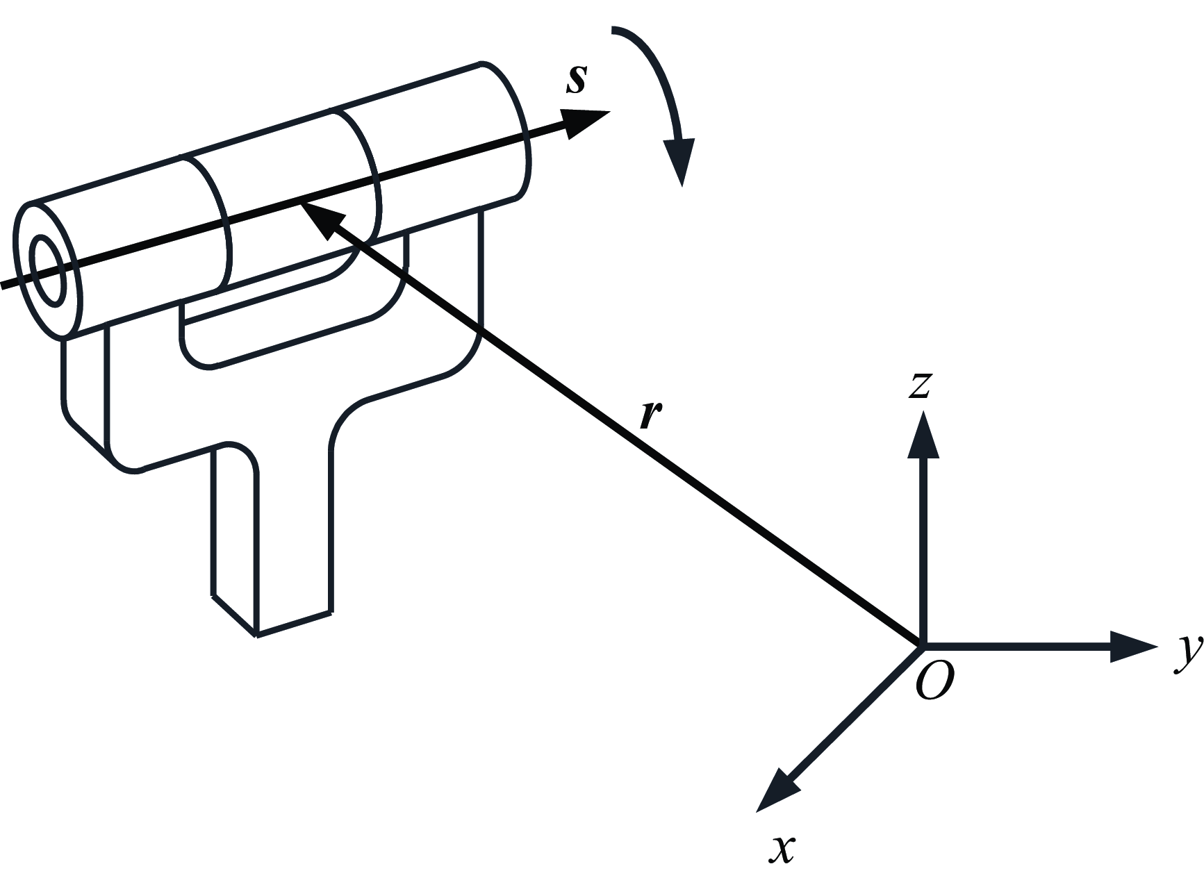
Kinematic joints are the fundamental units of robots. First, the models of rotational joint (R joints) and prismatic joints (P joints) are discussed, followed by the model of helical joints (H joints). Rotational joint, prismatic joint, and helical joint are denoted as R, P, and H joints respectively in the following.
The expressions of the finite screw generated by R, P, and H joints are placed at Appendix A.
3. Different compositions of generatrices and generating lines generating translations on quadric surfaces
We give research on special translational robots generating single/two-DoF translations in this section. Different from traditional translational robots, translations of special translational robots are not along a straight line or on a plane, but along a specific spatial curve or on a complex quadric surface.
3.1. The motion of single-DoF translations along spatial curves
3.1.1 Translations along a straight line
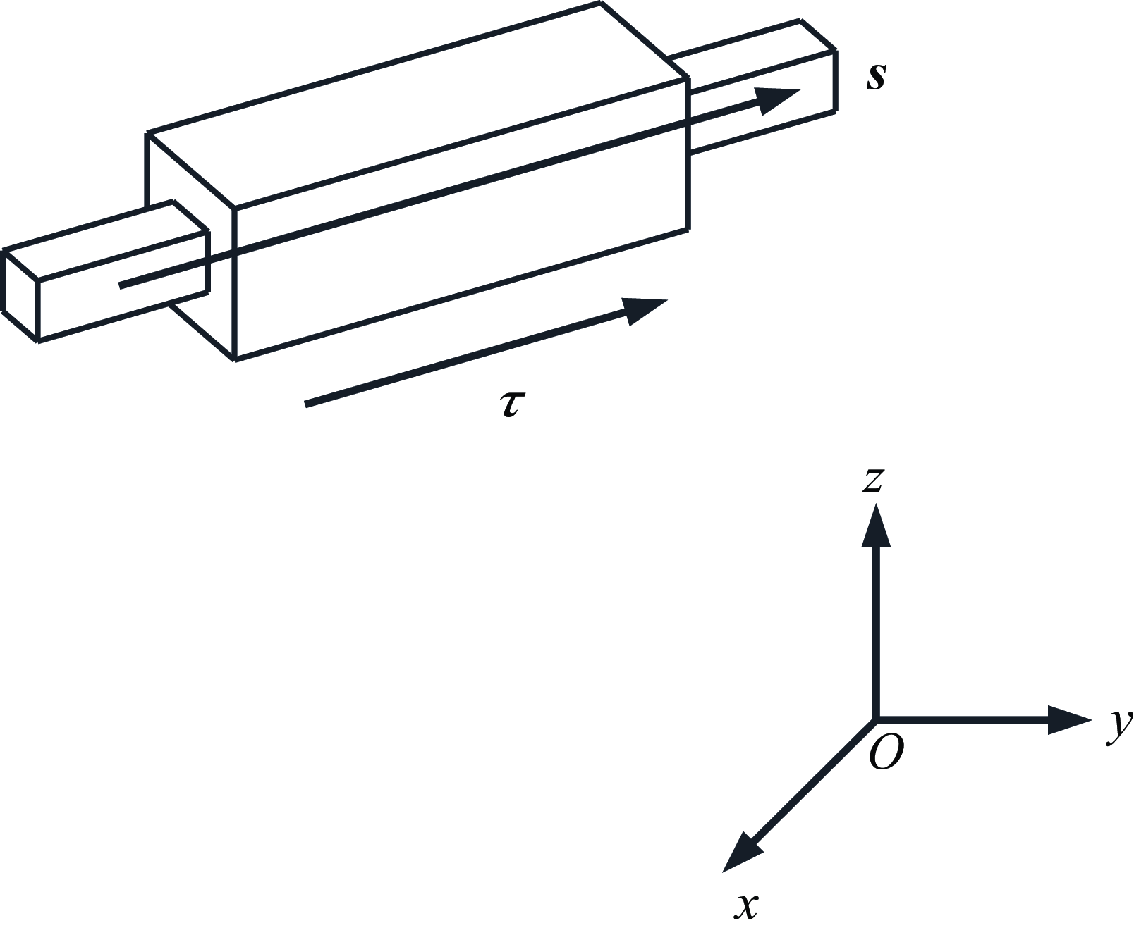
Appendix A shows that a P joint generates a translation along a straight line and reveals the finite screw of P joints (Figure A2). Translations along a straight line can be generated as
 \begin{equation} \left\{{\boldsymbol{S}}_{f}\right\}=\left\{\tau \left(\begin{array}{c} \mathbf{0}\\ {\boldsymbol{s}} \end{array}\right)\right\} \end{equation}
where denotations of
 $\tau$
and
 ${\boldsymbol{s}}$
are the same with those in Eq. (A2). The difference of translations along different straight lines is
 ${\boldsymbol{s}}$
.
3.1.2 Translations along a circle
For the circular translation generated by two parallel R joints, the generated motion can be expressed by finite screw theory as
 \begin{equation} \begin{aligned} \displaystyle\left\{{\boldsymbol{S}}_{f,2\mathrm{R}}\right\} & =\left\{2\tan \displaystyle\frac{\theta _{2}}{2}\left(\begin{array}{c} \displaystyle{\boldsymbol{s}}\\ {\boldsymbol{r}}_{2}\times {\boldsymbol{s}} \end{array}\right)\overline{\circ }2\tan \displaystyle\frac{\theta _{1}}{2}\left(\begin{array}{c} \displaystyle{\boldsymbol{s}}\\ {\boldsymbol{r}}_{1}\times {\boldsymbol{s}} \end{array}\right)\right\}\\ & =\left\{2\tan \displaystyle\frac{\theta _{1}+\theta _{2}}{2}\left(\begin{array}{c} {\boldsymbol{s}}\\ {\boldsymbol{r}}_{2}\times {\boldsymbol{s}} \end{array}\right)\overline{\circ }\left(\begin{array}{c} \mathbf{0}\\ \left(\exp \left(\theta _{1}\left[{\boldsymbol{s}}\times \right]\right)-{\boldsymbol{I}}_{3}\right)\left({\boldsymbol{r}}_{2}-{\boldsymbol{r}}_{1}\right) \end{array}\right)\right\} \end{aligned} \end{equation}
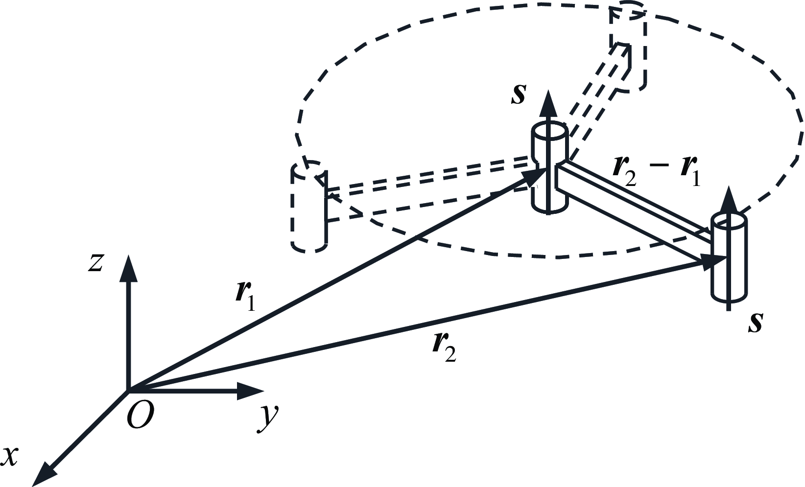
Equation (4) indicates that the motion generated by two parallel R joints consists of a rotation and a translation along a circle. The direction of the rotation axis is
 ${\boldsymbol{s}}$
, the plane of the circle is perpendicular to the corresponding R joint axis, and the radius of the circle is
 $\| {\boldsymbol{r}}_{2}-{\boldsymbol{r}}_{1}\|$
, as illustrated in Figure 1.
Translations along a circle generated by two R joints with parallel axes.

3.1.3 Translations along a helix
Following the procedure in Section 3.1.2, the translation along a helix generated by two parallel H joints is obtained as
 \begin{equation} \begin{aligned} \left\{{\boldsymbol{S}}_{f,2\mathrm{H}}\right\} & =\left\{\left(2\tan \displaystyle\frac{\theta _{2}}{2}\left(\begin{array}{c} {\boldsymbol{s}}\\ \displaystyle{\boldsymbol{r}}_{\mathrm{2}}\times {\boldsymbol{s}} \end{array}\right)+h_{2}\theta _{2}\left(\begin{array}{c} \mathbf{0}\\ {\boldsymbol{s}} \end{array}\right)\right)\overline{\circ }\left(2\tan \displaystyle\frac{\theta _{1}}{2}\left(\begin{array}{c} {\boldsymbol{s}}\\ {\boldsymbol{r}}_{1}\times {\boldsymbol{s}} \end{array}\right)+h_{1}\theta _{1}\left(\begin{array}{c} \mathbf{0}\\ {\boldsymbol{s}} \end{array}\right)\right)\right\}\\ & =\left\{2\tan \displaystyle\frac{\theta _{1}+\theta _{2}}{2}\left(\begin{array}{c} {\boldsymbol{s}}\\ {\boldsymbol{r}}_{\mathrm{2}}\times {\boldsymbol{s}} \end{array}\right)\overline{\circ }\left(\begin{array}{c} \mathbf{0}\\ \exp \left(\theta _{1}\left[{\boldsymbol{s}}_{1}\times \right]-{\boldsymbol{I}}_{3}\right)\left({\boldsymbol{r}}_{2}-{\boldsymbol{r}}_{1}\right)+\left(h_{1}\theta _{1}+h_{2}\theta _{2}\right){\boldsymbol{s}} \end{array}\right)\right\} \end{aligned} \end{equation}
Equation (5) reveals a fact that the motions generated by two parallel H joints are a rotation and a translation along a helix (Figure 2). In case
 $h_{2}$
is 0, the motion generator is reduced to a R joint and a H joint with the same rotation axis
 ${\boldsymbol{s}}$
, and the motions are still a rotation and a translation along a helix.
Translations along a helix generated by two H joints with parallel axes.

We have illustrated translations along a straight line, translations along a circle, and translations along a helix by a P joint, two parallel R joints, and two parallel H joints respectively. It is noted that all kinds of translations mentioned here only have single-DoF, and this section provides foundations for the following research on two-DoF translations on quadric surfaces.
3.2. The motion of two-DoF translations on quadric surfaces
Two single-DoF translations can constitute a two-DoF translation, so a two-DoF translation can be obtained by synthesizing two simple translations. According to this nature, we propose a general approach for synthesizing robots generating translations on quadric surfaces in Section 3.2.
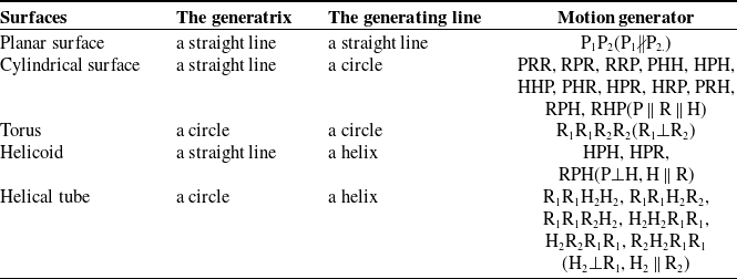
We introduce two concepts from geometry into the theory of robot design, one is generatrix defined as the fundamental trajectory of translations and the other is generating line introduced as the lead trajectory of translations in this article. The generatrix and the generating line can be utilized to generate all kinds of translations on quadric surfaces. For example, a translation along a circle and a translation along a straight line can be synthesized as a two-DoF translation on a cylindrical surface, and two translations along circles where two planes of circles are perpendicular to each other can constitute a two-DoF translation on toruses. We give the research on four translations on quadric surfaces obtained by combing the three single-DoF translations in Section 3.1, which are translations on a cylindrical surface, translations on toruses, translations on helicoids, and translations on a helical tube respectively, and list the motion generators of these translations.
3.2.1 Translations on a cylindrical surface
For a cylindrical surface from geometry, the generatrix is a straight line and the generating line is a circle, which are the same for robot design. Translations on a cylindrical surface can be constituted by a translation along a straight line connecting a translation along a circle, so the motion generator is a P joint connecting two R joints in series, which is denoted PRR (Figure 3). The motion is expressed as
Cylindrical surface with
 ${\boldsymbol{s}}_{1}\parallel{\boldsymbol{s}}_{2}$
.

 \begin{equation} \begin{aligned} \left\{{\boldsymbol{S}}_{f,\mathrm{PRR}}\right\} & =\left\{2\tan \displaystyle\frac{\theta _{2}}{2}\left(\begin{array}{c} {\boldsymbol{s}}_{2}\\ {\boldsymbol{r}}_{2}\times {\boldsymbol{s}}_{2} \end{array}\right)\overline{\circ }2\tan \displaystyle\frac{\theta _{1}}{2}\left(\begin{array}{c} {\boldsymbol{s}}_{2}\\ {\boldsymbol{r}}_{1}\times {\boldsymbol{s}}_{2} \end{array}\right)\overline{\circ }\tau \left(\begin{array}{c} \mathbf{0}\\ {\boldsymbol{s}}_{1} \end{array}\right)\right\}\\ & =\left\{2\tan \displaystyle\frac{\theta _{1}+\theta _{2}}{2}\left(\begin{array}{c} {\boldsymbol{s}}_{2}\\ {\boldsymbol{r}}_{2}\times {\boldsymbol{s}}_{2} \end{array}\right)\overline{\circ }\left(\begin{array}{c} \mathbf{0}\\ \exp \left(\theta _{1}\left[{\boldsymbol{s}}_{1}\times \right]-{\boldsymbol{I}}_{3}\right)\left({\boldsymbol{r}}_{2}-{\boldsymbol{r}}_{1}\right)\boldsymbol{+}\tau {\boldsymbol{s}}_{1} \end{array}\right)\right\} \end{aligned} \end{equation}
where
 $\left(\begin{array}{c} \mathbf{0}\\ (\exp (\theta _{1}[{\boldsymbol{s}}_{2}\times])-{\boldsymbol{I}}_{3})({\boldsymbol{r}}_{2}-{\boldsymbol{r}}_{1})+\tau {\boldsymbol{s}}_{1} \end{array}\right)$
is the translation on cylindrical surface (Figure 3). The trajectory of translation is a right cylinder with
 ${\boldsymbol{s}}_{1}\parallel{\boldsymbol{s}}_{2}$
and is a slanting cylinder with
 ${\boldsymbol{s}}_{1}\nparallel{\boldsymbol{s}}_{2}$
, and the blue P joint represents the generatrix and two green R joints represent the generating line.
3.2.2 Translations on toruses
Similar to the procedure of generating translations on a cylindrical surface, the translation on toruses can be obtained with the same approach. The generatrix and the generating line are circles, and motion generator is four R joints which is formulated as
 \begin{equation} \begin{aligned} \left\{{\boldsymbol{S}}_{f}\right\} & =\left\{2\tan \displaystyle\frac{\theta _{4}}{2}\left(\begin{array}{c} {\boldsymbol{s}}_{2}\\ {\boldsymbol{r}}_{4}\times {\boldsymbol{s}}_{2} \end{array}\right)\overline{\circ }2\tan \displaystyle\frac{\theta _{3}}{2}\left(\begin{array}{c} {\boldsymbol{s}}_{2}\\ {\boldsymbol{r}}_{3}\times {\boldsymbol{s}}_{2} \end{array}\right)\overline{\circ }2\tan \displaystyle\frac{\theta _{2}}{2}\left(\begin{array}{c} {\boldsymbol{s}}_{1}\\ {\boldsymbol{r}}_{2}\times {\boldsymbol{s}}_{1} \end{array}\right)\overline{\circ }2\tan \displaystyle\frac{\theta _{1}}{2}\left(\begin{array}{c} {\boldsymbol{s}}_{1}\\ {\boldsymbol{r}}_{1}\times {\boldsymbol{s}}_{1} \end{array}\right)\right\}\\ & =\left\{\begin{array}{l} 2\tan \displaystyle\frac{\theta _{4}+\theta _{3}}{2}\left(\begin{array}{c} {\boldsymbol{s}}_{2}\\ {\boldsymbol{r}}_{4}\times {\boldsymbol{s}}_{2} \end{array}\right)\overline{\circ }\left(\begin{array}{c} \mathbf{0}\\ \left(\exp \left(\theta _{3}\left[{\boldsymbol{s}}_{2}\times \right]\right)-{\boldsymbol{I}}_{3}\right)\left({\boldsymbol{r}}_{4}-{\boldsymbol{r}}_{3}\right) \end{array}\right)\overline{\circ }2\tan \displaystyle\frac{\theta _{2}+\theta _{1}}{2}\left(\begin{array}{c} {\boldsymbol{s}}_{1}\\ {\boldsymbol{r}}_{2}\times {\boldsymbol{s}}_{1} \end{array}\right)\\ \overline{\circ }\left(\begin{array}{c} \mathbf{0}\\ \left(\exp \left(\theta _{1}\left[{\boldsymbol{s}}_{1}\times \right]\right)-{\boldsymbol{I}}_{3}\right)\left({\boldsymbol{r}}_{2}-{\boldsymbol{r}}_{1}\right) \end{array}\right) \end{array}\right\}\\ & =\left\{\begin{array}{l} 2\tan \displaystyle\frac{\theta _{4}+\theta _{3}}{2}\left(\begin{array}{c} {\boldsymbol{s}}_{2}\\ {\boldsymbol{r}}_{4}\times {\boldsymbol{s}}_{2} \end{array}\right)\overline{\circ }\left(\begin{array}{c} \mathbf{0}\\ \left(\exp \left(\theta _{3}\left[{\boldsymbol{s}}_{2}\times \right]\right)-{\boldsymbol{I}}_{3}\right)\left({\boldsymbol{r}}_{4}-{\boldsymbol{r}}_{3}\right) \end{array}\right)\\ \overline{\circ }\left(\begin{array}{c} \mathbf{0}\\ \left(\exp \left(-\theta _{2}\left[{\boldsymbol{s}}_{1}\times \right]\right)-\exp \left(-\left(\theta _{2}+\theta _{1}\right)\left[{\boldsymbol{s}}_{1}\times \right]\right)\right)\left({\boldsymbol{r}}_{2}-{\boldsymbol{r}}_{1}\right) \end{array}\right)\overline{\circ }2\tan \displaystyle\frac{\theta _{2}+\theta _{1}}{2}\left(\begin{array}{c} {\boldsymbol{s}}_{1}\\ {\boldsymbol{r}}_{2}\times {\boldsymbol{s}}_{1} \end{array}\right) \end{array}\right\} \end{aligned} \end{equation}
Equation (7) reveals the robot generating translations on tours, which is consisted of four R joints.
 $\left\{\left(\begin{array}{c} \mathbf{0}\\ (\exp (\theta _{3}[{\boldsymbol{s}}_{\mathrm{2}}\times])-{\boldsymbol{I}}_{3})({\boldsymbol{r}}_{4}-{\boldsymbol{r}}_{3}) \end{array}\right)\overline{\circ }\left(\begin{array}{c} \mathbf{0}\\ (\exp (-\theta _{2}[{\boldsymbol{s}}_{1}\times])-\exp (-(\theta _{2}+\theta _{1})[{\boldsymbol{s}}_{1}\times]))({\boldsymbol{r}}_{2}-{\boldsymbol{r}}_{1}) \end{array}\right)\right\}$
is the translation on toruses (Figure 4) and
 ${\boldsymbol{s}}_{1}\bot {\boldsymbol{s}}_{2}$
.
Toruses with
 ${\boldsymbol{s}}_{1}\bot {\boldsymbol{s}}_{2}$
.

It is clear that two blue R joints form the generatrix and two green R joints constitute the generating line, so the generatrix and the generating line are all circles. It is noted that two circles are perpendicular to each other.
3.2.3 Translations on helicoids/helical tubes
The generatrix of helicoid is a straight line, the generating line is a helix, and the motion generator is a P joint and two H joints. The motion of HPH serial limb is
 \begin{equation} \begin{aligned} &\!\!\left\{{\boldsymbol{S}}_{f,\mathrm{HPH}}\right\}=\left\{\left(2\tan \displaystyle\frac{\theta _{2}}{2}\left(\begin{array}{c} {\boldsymbol{s}}_{2}\\ {\boldsymbol{r}}_{\mathrm{2}}\times {\boldsymbol{s}}_{2} \end{array}\right)+h_{2}\theta _{2}\left(\begin{array}{c} \mathbf{0}\\ {\boldsymbol{s}}_{2} \end{array}\right)\right)\overline{\circ }\tau \left(\begin{array}{c} \mathbf{0}\\ \mathbf{s}_{1} \end{array}\right)\overline{\circ }\left(2\tan \displaystyle\frac{\theta _{1}}{2}\left(\begin{array}{c} {\boldsymbol{s}}_{2}\\ {\boldsymbol{r}}_{1}\times {\boldsymbol{s}}_{2} \end{array}\right)+h_{1}\theta _{1}\left(\begin{array}{c} \mathbf{0}\\ {\boldsymbol{s}}_{2} \end{array}\right)\right)\right\}\\ &\!\! =\left\{2\tan \displaystyle\frac{\theta _{1}+\theta _{2}}{2}\left(\begin{array}{c} {\boldsymbol{s}}_{2}\\ {\boldsymbol{r}}_{\mathrm{2}}\times {\boldsymbol{s}}_{2} \end{array}\right)\overline{\circ }\left(\begin{array}{c} \mathbf{0}\\ \exp \left(\theta _{1}\left[{\boldsymbol{s}}_{2}\times \right]-{\boldsymbol{I}}_{3}\right)\left({\boldsymbol{r}}_{2}-{\boldsymbol{r}}_{1}\right)\boldsymbol{+}\left(h_{2}\theta _{2}+h_{1}\theta _{1}\right){\boldsymbol{s}}_{2}+\exp \left(\theta _{1}\left[{\boldsymbol{s}}_{2}\times \right]\right)\tau {\boldsymbol{s}}_{1} \end{array}\right)\right\} \end{aligned} \end{equation}
where
 $\left(\begin{array}{c} \mathbf{0}\\ \exp (\theta _{1}[{\boldsymbol{s}}_{2}\times]-{\boldsymbol{I}}_{3})({\boldsymbol{r}}_{2}-{\boldsymbol{r}}_{1})\boldsymbol{+}(h_{2}\theta _{2}+h_{1}\theta _{1}){\boldsymbol{s}}_{2}+\exp (\theta _{1}[{\boldsymbol{s}}_{2}\times])\tau {\boldsymbol{s}}_{1} \end{array}\right)$
is the translation on the helicoid with the condition
 ${\boldsymbol{s}}_{1}\bot {\boldsymbol{s}}_{2}$
. As shown in Figure 5, two green parallel H joints generating a translation along a helix constitute the generating line, and a blue P joint generating a translation along a straight line constitutes the generatrix.
Translation on helicoids.

According to the motion of translation on helicoids, we can reveal the nature of translations on a helical tube whose generatrix is a circle and the generating line is a still a helix, and the motion is expressed as
 \begin{equation} \begin{aligned} & \left\{{\boldsymbol{S}}_{f,\mathrm{RRHH}}\right\} =\left\{\begin{array}{l} \left(2\tan \displaystyle\frac{\theta _{4}}{2}\left(\begin{array}{c} {\boldsymbol{s}}_{2}\\ {\boldsymbol{r}}_{4}\times {\boldsymbol{s}}_{2} \end{array}\right)+h_{2}\theta _{4}\left(\begin{array}{c} \mathbf{0}\\ {\boldsymbol{s}}_{2} \end{array}\right)\right)\overline{\circ }\left(2\tan \displaystyle\frac{\theta _{3}}{2}\left(\begin{array}{c} {\boldsymbol{s}}_{2}\\ {\boldsymbol{r}}_{3}\times {\boldsymbol{s}}_{2} \end{array}\right)+h_{1}\theta _{3}\left(\begin{array}{c} \mathbf{0}\\ {\boldsymbol{s}}_{2} \end{array}\right)\right)\\ \overline{\circ }2\tan \displaystyle\frac{\theta _{2}}{2}\left(\begin{array}{c} {\boldsymbol{s}}_{1}\\ {\boldsymbol{r}}_{2}\times {\boldsymbol{s}}_{1} \end{array}\right)\overline{\circ }2\tan \displaystyle\frac{\theta _{1}}{2}\left(\begin{array}{c} {\boldsymbol{s}}_{1}\\ {\boldsymbol{r}}_{1}\times {\boldsymbol{s}}_{1} \end{array}\right) \end{array}\right\}\\ & =\left\{\begin{array}{l} 2\tan \displaystyle\frac{\theta _{4}+\theta _{3}}{2}\left(\begin{array}{c} {\boldsymbol{s}}_{2}\\ {\boldsymbol{r}}_{4}\times {\boldsymbol{s}}_{2} \end{array}\right)\overline{\circ }\left(\begin{array}{c} \mathbf{0}\\ \exp \left(\theta _{3}\left[{\boldsymbol{s}}_{2}\times \right]-{\boldsymbol{I}}_{3}\right)\left({\boldsymbol{r}}_{4}-{\boldsymbol{r}}_{3}\right)\boldsymbol{+}\left(h_{2}\theta _{2}+h_{1}\theta _{1}\right){\boldsymbol{s}}_{2} \end{array}\right)\\ \overline{\circ }\left(\begin{array}{c} \mathbf{0}\\ \exp \left(\theta _{1}\left[{\boldsymbol{s}}_{1}\times \right]-{\boldsymbol{I}}_{3}\right)\left({\boldsymbol{r}}_{2}-{\boldsymbol{r}}_{1}\right) \end{array}\right)\overline{\circ }2\tan \displaystyle\frac{\theta _{2}+\theta _{1}}{2}\left(\begin{array}{c} {\boldsymbol{s}}_{1}\\ \left({\boldsymbol{r}}_{2}+\exp \left(\theta _{1}\left[{\boldsymbol{s}}_{1}\times \right]-{\boldsymbol{I}}_{3}\right)\left({\boldsymbol{r}}_{2}-{\boldsymbol{r}}_{1}\right)\right)\times {\boldsymbol{s}}_{1} \end{array}\right) \end{array}\right\} \end{aligned} \end{equation}
Equation (9) presents the composition of robot generating translations on helical tube, where
 $\left(\begin{array}{c} \mathbf{0}\\ \exp (\theta _{3}[{\boldsymbol{s}}_{2}\times]-{\boldsymbol{I}}_{3})({\boldsymbol{r}}_{4}-{\boldsymbol{r}}_{3})+(h_{1}\theta _{1}+h_{2}\theta _{2}){\boldsymbol{s}}_{2} \end{array}\right)\overline{\circ }\left(\begin{array}{c} \mathbf{0}\\ \exp (\theta _{1}[{\boldsymbol{s}}_{1}\times]-{\boldsymbol{I}}_{3})({\boldsymbol{r}}_{2}-{\boldsymbol{r}}_{1}) \end{array}\right)$
in Eq. (9) is the translation on a helical tube (Figure 6) with the common condition
 ${\boldsymbol{s}}_{1}\bot {\boldsymbol{s}}_{2}$
. Two green parallel H joints generating a translation along a helix constitute the generating line, and two blue R joints generating a circular translation constitute the generatrix.
We list five translations on quadric surfaces mentioned in this section and their motion generators in Table 1. The above text proves the feasibility of robots generating toruses and lays the theoretical foundation for the following type synthesis of robots. We have illustrated the principle of generating translations on quadric surfaces with the generatrixs and the generating lines in this section, and we will synthesize a closed-loop robot for machining and manufacturing of toruses to validate the feasibility of this approach.
The generators of two-DoF translations on quadric surfaces.

Translation on helical tubes.

4. Design and synthesis of a closed-loop robot for machining and manufacturing of toruses
We give the procedure of synthesizing a closed-loop robot for machining and manufacturing of toruses in this section. First, we synthesize the standard type of the closed-loop robot, and then we give the procedure of synthesizing the derived type of this robot. We give the assembly conditions at the end of the section.
4.1. The standard type synthesis of the closed-loop robot
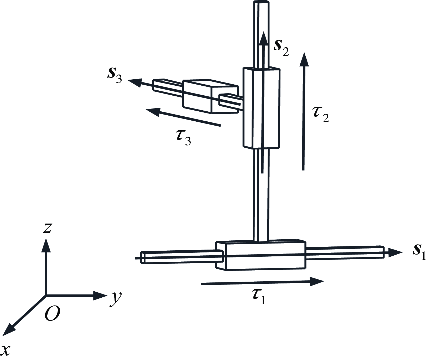
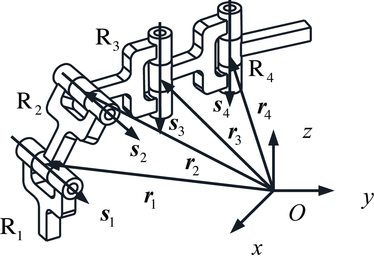
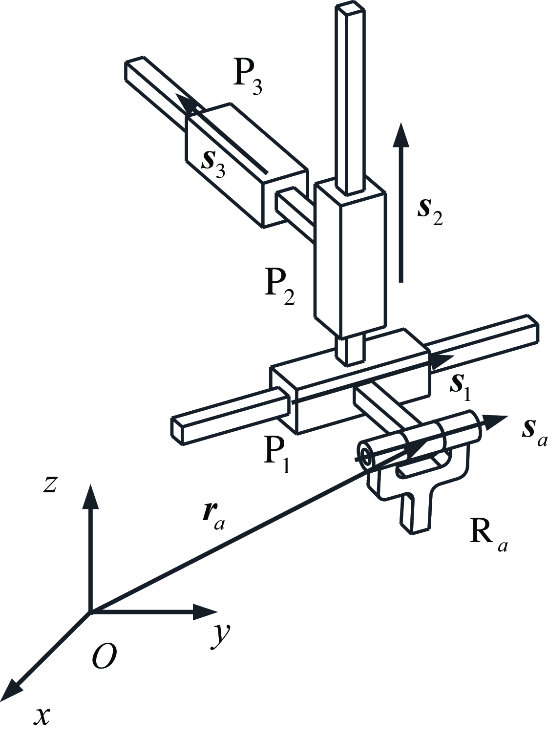
The standard type of the closed-loop robot for machining and manufacturing of toruses consists of two limbs connected in parallel to the moving and fixed platforms. As shown in Figure 7, standard limb 1 is composed of three P joints connected in series with mutually perpendicular axes, which can generate spatial three-DoF translations. As illustrated in Figure 8, standard limb 2 is composed of four R joints, generating two-DoF translations. Since both limbs share the same moving platform, the final output motion of the robot at the end platform is two-DoF translation.
Three-DoF translations generated by standard serial kinematic limb 1.

Four-DoF (two translations and two rotations) generated by standard serial kinematic limb 2.

4.1.1 Synthesis of standard limb 1
First, a standard limb 1 composed of three mutually perpendicular P joints in series is designed (Figure 7), and the motion generated by limb 1 is represented by finite screw as
 \begin{equation} \begin{aligned} \left\{{\boldsymbol{S}}_{f,1}\right\} & =\left\{{\boldsymbol{S}}_{f,1,3}\right\}\overline{\circ }\left\{{\boldsymbol{S}}_{f,1,2}\right\}\overline{\circ }\left\{{\boldsymbol{S}}_{f,1,1}\right\}\\ & =\left\{\tau _{3}\left(\begin{array}{c} \mathbf{0}\\ {\boldsymbol{s}}_{3} \end{array}\right)\overline{\circ }\tau _{2}\left(\begin{array}{c} \mathbf{0}\\ {\boldsymbol{s}}_{2} \end{array}\right)\overline{\circ }\tau _{1}\left(\begin{array}{c} \mathbf{0}\\ {\boldsymbol{s}}_{1} \end{array}\right)\right\} \end{aligned} \end{equation}
where
 ${\boldsymbol{s}}_{i}$
(
 $\| {\boldsymbol{s}}_{i}\| =1, i=\mathrm{1,2,3}$
) are the unit direction vectors of the three P joints, the movement directions of the three P joints are perpendicular to each other (
 ${\boldsymbol{s}}_{1}\bot {\boldsymbol{s}}_{2}\bot {\boldsymbol{s}}_{3}$
), and
 $\tau _{i}$
(
 $i=\mathrm{1,2,3}$
) represent the distance each P joint moving from its initial position. Equation (10) clearly indicates that the output motion of limb 1 is three-DoF translation in space.
4.1.2 Synthesis of standard limb 2
The standard limb 2 consists of four R joints connected in series (Figure 8). It is noted that
 $\mathrm{R}_{1}\parallel \mathrm{R}_{2}, \mathrm{R}_{3}\parallel \mathrm{R}_{4}$
and
 ${\boldsymbol{s}}_{4}\bot {\boldsymbol{s}}_{5}$
. The motion generated by standard limb 2 is formulated as
 \begin{equation} \begin{aligned} \left\{{\boldsymbol{S}}_{f,2}\right\} & =\left\{{\boldsymbol{S}}_{f,2,4}\right\}\overline{\circ }\left\{{\boldsymbol{S}}_{f,2,3}\right\}\overline{\circ }\left\{{\boldsymbol{S}}_{f,2,2}\right\}\overline{\circ }\left\{{\boldsymbol{S}}_{f,2,1}\right\}\\ & =\left\{2\tan \displaystyle\frac{\theta _{4}}{2}\left(\begin{array}{c} {\boldsymbol{s}}_{5}\\ {\boldsymbol{r}}_{4}\times {\boldsymbol{s}}_{5} \end{array}\right)\overline{\circ }2\tan \displaystyle\frac{\theta _{3}}{2}\left(\begin{array}{c} {\boldsymbol{s}}_{5}\\ {\boldsymbol{r}}_{3}\times {\boldsymbol{s}}_{5} \end{array}\right)\overline{\circ }2\tan \displaystyle\frac{\theta _{2}}{2}\left(\begin{array}{c} {\boldsymbol{s}}_{4}\\ {\boldsymbol{r}}_{2}\times {\boldsymbol{s}}_{4} \end{array}\right)\overline{\circ }2\tan \displaystyle\frac{\theta _{1}}{2}\left(\begin{array}{c} {\boldsymbol{s}}_{4}\\ {\boldsymbol{r}}_{1}\times {\boldsymbol{s}}_{4} \end{array}\right)\right\}\\ & =\left\{\begin{array}{l} 2\tan \displaystyle\frac{\theta _{4}+\theta _{3}}{2}\left(\begin{array}{c} {\boldsymbol{s}}_{5}\\ {\boldsymbol{r}}_{4}\times {\boldsymbol{s}}_{5} \end{array}\right)\overline{\circ }\left(\begin{array}{c} \mathbf{0}\\ \left(\exp \left(\theta _{3}\left[{\boldsymbol{s}}_{5}\times \right]\right)-{\boldsymbol{I}}_{3}\right)\left({\boldsymbol{r}}_{4}-{\boldsymbol{r}}_{3}\right) \end{array}\right)\\ \overline{\circ }2\tan \displaystyle\frac{\theta _{2}+\theta _{1}}{2}\left(\begin{array}{c} {\boldsymbol{s}}_{4}\\ {\boldsymbol{r}}_{2}\times {\boldsymbol{s}}_{4} \end{array}\right)\overline{\circ }\left(\begin{array}{c} \mathbf{0}\\ \left(\exp \left(\theta _{1}\left[{\boldsymbol{s}}_{4}\times \right]\right)-{\boldsymbol{I}}_{3}\right)\left({\boldsymbol{r}}_{2}-{\boldsymbol{r}}_{1}\right) \end{array}\right) \end{array}\right\} \end{aligned} \end{equation}
where the denotations of
 ${\boldsymbol{s}}_{i}, {\boldsymbol{r}}_{i}, \theta _{i}, [{\boldsymbol{s}}_{i}\times]$
are referred to those appear above.
Equation (11) reveals that the motions generated by limb 2 are a rotation about the axis of R4 joint and a circular translation, as well as a rotation about the axis of R2 joint and another circular translation. The first circle is perpendicular to the axis of R4 joint, with a radius of
 $\| {\boldsymbol{r}}_{4}-{\boldsymbol{r}}_{3}\|$
, while the second circle is perpendicular to the axis of R2 joint, with a radius of
 $\| {\boldsymbol{r}}_{2}-{\boldsymbol{r}}_{1}\|$
.
4.1.3 Assembly of standard type of the closed-loop robot
The composition and specific position of the two standard limbs have been provided above, and the finite motion of the moving platform of the closed-loop robot is the intersection of the finite motions of the two limbs. According to Eq. (1), the finite screw
 $\{{\boldsymbol{S}}_{f,\mathrm{PM}}\}$
of the moving platform is
 \begin{equation} \begin{aligned} \left\{{\boldsymbol{S}}_{f,\mathrm{PM}}\right\} & =\left\{{\boldsymbol{S}}_{f,1}\right\}\cap \left\{{\boldsymbol{S}}_{f,2}\right\}\\ & =\left\{\begin{array}{l} \left(\tau _{3}\left(\begin{array}{c} \mathbf{0}\\ {\boldsymbol{s}}_{3} \end{array}\right)\overline{\circ }\tau _{2}\left(\begin{array}{c} \mathbf{0}\\ {\boldsymbol{s}}_{2} \end{array}\right)\overline{\circ }\tau _{1}\left(\begin{array}{c} \mathbf{0}\\ {\boldsymbol{s}}_{1} \end{array}\right)\right)\cap \\ \left(\begin{array}{c} 2\tan \displaystyle\frac{\theta _{4}+\theta _{3}}{2}\left(\begin{array}{c} {\boldsymbol{s}}_{5}\\ {\boldsymbol{r}}_{4}\times {\boldsymbol{s}}_{5} \end{array}\right)\overline{\circ }\left(\begin{array}{c} \mathbf{0}\\ \left(\exp \left(\theta _{3}\left[{\boldsymbol{s}}_{5}\times \right]\right)-{\boldsymbol{I}}_{3}\right)\left({\boldsymbol{r}}_{4}-{\boldsymbol{r}}_{3}\right) \end{array}\right)\\ \overline{\circ }2\tan \displaystyle\frac{\theta _{2}+\theta _{1}}{2}\left(\begin{array}{c} {\boldsymbol{s}}_{4}\\ {\boldsymbol{r}}_{2}\times {\boldsymbol{s}}_{4} \end{array}\right)\overline{\circ }\left(\begin{array}{c} \mathbf{0}\\ \left(\exp \left(\theta _{1}\left[{\boldsymbol{s}}_{4}\times \right]\right)-{\boldsymbol{I}}_{3}\right)\left({\boldsymbol{r}}_{2}-{\boldsymbol{r}}_{1}\right) \end{array}\right) \end{array}\right) \end{array}\right\}\\ & =\left\{\left(\begin{array}{c} \mathbf{0}\\ \left(\exp \left(\theta _{3}\left[{\boldsymbol{s}}_{5}\times \right]\right)-{\boldsymbol{I}}_{3}\right)\left({\boldsymbol{r}}_{4}-{\boldsymbol{r}}_{3}\right) \end{array}\right)\overline{\circ }\left(\begin{array}{c} \mathbf{0}\\ \left(\exp \left(\theta _{1}\left[{\boldsymbol{s}}_{4}\times \right]\right)-{\boldsymbol{I}}_{3}\right)\left({\boldsymbol{r}}_{2}-{\boldsymbol{r}}_{1}\right) \end{array}\right)\right\}\\ & =\left\{\left(\begin{array}{c} \mathbf{0}\\ \left(\exp \left(\theta _{3}\left[{\boldsymbol{s}}_{5}\times \right]\right)-{\boldsymbol{I}}_{3}\right)\left({\boldsymbol{r}}_{4}-{\boldsymbol{r}}_{3}\right)+\left(\exp \left(\theta _{1}\left[{\boldsymbol{s}}_{4}\times \right]\right)-{\boldsymbol{I}}_{3}\right)\left({\boldsymbol{r}}_{2}-{\boldsymbol{r}}_{1}\right) \end{array}\right)\right\} \end{aligned} \end{equation}
Equation (12) reveals that the motion of the robot moving platform is a translation on a torus, where the final output motion of the robot consists of two circular translations, and the planes of the two circles are perpendicular to each other.
A quadric surface is a two-dimensional surface, and its expression involves two independent parameters. For the given robot, the vectors
 ${\boldsymbol{s}}_{5}, {\boldsymbol{s}}_{4}, {\boldsymbol{r}}_{4}, {\boldsymbol{r}}_{3}, {\boldsymbol{r}}_{2}, {\boldsymbol{r}}_{1}$
in Eq. (13) are all known, with only
 $\theta _{3}$
and
 $\theta _{1}$
being unknown parameters. Therefore, the resultant motion of two circular translations is a two-DoF motion on torus (Figure 9).
Closed-loop robot for machining and manufacturing of torus.

 \begin{equation} \left\{\left(\begin{array}{c} \mathbf{0}\\ \left(\exp \left(\theta _{3}\left[{\boldsymbol{s}}_{5}\times \right]\right)-{\boldsymbol{I}}_{3}\right)\left({\boldsymbol{r}}_{4}-{\boldsymbol{r}}_{3}\right)+\left(\exp \left(\theta _{1}\left[{\boldsymbol{s}}_{4}\times \right]\right)-{\boldsymbol{I}}_{3}\right)\left({\boldsymbol{r}}_{2}-{\boldsymbol{r}}_{1}\right) \end{array}\right)\right\} \end{equation}
4.2. Synthesis of derived types of the closed-loop robot
We will explore the procedure of synthesizing derived types of this robot with the help of finite screw theory in this section. By adding one or two R joints to the two standard limbs, four-DoF and five-DoF derived limbs are obtained, leading to the derived types of the robot.
For the standard limb 1 denoted as P1P2P3 shown in Figure 7, by merely swapping the positions of three P joints, we obtain P1P3P2, P2P1P3, P2P3P1, P3P1P2, and P3P2P1. These are considered the same kinematic limb in this paper and will not be discussed further.
4.2.1 Synthesis of four-DoF derived limbs for limb 1
The derived limb RaP1P2P3 is obtained by adding a R joint to the standard limb 1, with its finite screw
 $\{{\boldsymbol{S}}_{f{,1_{\mathrm{I}}}}\}$
expressed as followed.
 \begin{equation} \left\{{\boldsymbol{S}}_{f{,1_{\mathrm{I}}}}\right\}=\left\{\tau _{3}\left(\begin{array}{c} \mathbf{0}\\ {\boldsymbol{s}}_{3} \end{array}\right)\overline{\circ }\tau _{2}\left(\begin{array}{c} \mathbf{0}\\ {\boldsymbol{s}}_{2} \end{array}\right)\overline{\circ }\tau _{1}\left(\begin{array}{c} \mathbf{0}\\ {\boldsymbol{s}}_{1} \end{array}\right)\overline{\circ }2\tan \displaystyle\frac{\theta _{a}}{2}\left(\begin{array}{c} {\boldsymbol{s}}_{a}\\ {\boldsymbol{r}}_{a}\times {\boldsymbol{s}}_{a} \end{array}\right)\right\} \end{equation}
This derived limb has four degrees of freedom with the positions of the three P joints unchanged. The positions and axis directions of the R joints are shown in Figure 10. The rotational part of the finite screw in the derived limb does not intersect with the finite screw of the standard limb 2 causing the rotational part to offset, and the final output of the moving platform of the robot is a two-DoF translation on torus.
Derived limb
 $\mathrm{R}_{a}\mathrm{P}_{1}\mathrm{P}_{2}\mathrm{P}_{3}$
.

Case 1: change the types of joints
For the derived limb R
a
P1P2P3, more derived types can be obtained through changing the type or position of the joints. Replace one or two P joints with R joints, for example, replace P1 in the R
a
P1P2P3 limb with
 $\mathrm{R}_{{a_{1}}}$
(where the axis of R
a
is rotated 45° counterclockwise to form
 $\mathrm{R}_{{a_{1}}}$
), and then get the derived limb
 $\mathrm{R}_{{a_{1}}}\mathrm{R}_{{a_{1}}}\mathrm{P}_{2}\mathrm{P}_{3}$
shown in Figure 11.
 $\{{\boldsymbol{S}}_{f{,1_{\mathrm{II}}}}\}$
generated by the derived limb can be expressed as
 \begin{equation} \begin{aligned} \left\{{\boldsymbol{S}}_{f{,1_{\mathrm{II}}}}\right\} & =\left\{\tau _{3}\left(\begin{array}{c} \mathbf{0}\\ {\boldsymbol{s}}_{3} \end{array}\right)\overline{\circ }\tau _{2}\left(\begin{array}{c} \mathbf{0}\\ {\boldsymbol{s}}_{2} \end{array}\right)\overline{\circ }2\tan \displaystyle\frac{\theta _{{a_{2}}}}{2}\left(\begin{array}{c} {\boldsymbol{s}}_{{a_{1}}}\\ {\boldsymbol{r}}_{{a_{2}}}\times {\boldsymbol{s}}_{{a_{1}}} \end{array}\right)\overline{\circ }2\tan \displaystyle\frac{\theta _{{a_{1}}}}{2}\left(\begin{array}{c} {\boldsymbol{s}}_{{a_{1}}}\\ {\boldsymbol{r}}_{{a_{1}}}\times {\boldsymbol{s}}_{{a_{1}}} \end{array}\right)\right\}\\ & =\left\{\begin{array}{l} \tau _{3}\left(\begin{array}{c} \mathbf{0}\\ {\boldsymbol{s}}_{3} \end{array}\right)\overline{\circ }\tau _{2}\left(\begin{array}{c} \mathbf{0}\\ {\boldsymbol{s}}_{2} \end{array}\right)\overline{\circ }\left(\begin{array}{c} \mathbf{0}\\ \left(\exp \left(-{\unicode[Arial]{x03B8}} _{{a_{2}}}\left[{\boldsymbol{s}}_{{a_{1}}}\times \right]\right)-\exp \left(-\displaystyle\sum _{i=1}^{2}{\unicode[Arial]{x03B8}} _{{a_{i}}}\left[{\boldsymbol{s}}_{{a_{1}}}\times \right]\right)\right)\left({\boldsymbol{r}}_{{a_{2}}}-{\boldsymbol{r}}_{{a_{1}}}\right) \end{array}\right)\\ \overline{\circ }2\tan \displaystyle\frac{\displaystyle\sum _{i=1}^{2}{\unicode[Arial]{x03B8}} _{{a_{i}}}}{2}\left(\begin{array}{c} {\boldsymbol{s}}_{{a_{1}}}\\ {\boldsymbol{r}}_{{a_{2}}}\times {\boldsymbol{s}}_{{a_{1}}} \end{array}\right) \end{array}\right\} \end{aligned} \end{equation}
where the third factor is a translation along a circle with a radius of
 $\| {\boldsymbol{r}}_{{a_{2}}}-{\boldsymbol{r}}_{{a_{1}}}\|$
and the plane of the circle is perpendicular to
 $S_{a_{\mathrm{1}}}$
. When
 $\| {\boldsymbol{r}}_{{a_{2}}}-{\boldsymbol{r}}_{{a_{\mathrm{2}}}}\| \rightarrow \infty$
and
 ${\boldsymbol{s}}_{{a_{\mathrm{1}}}}\times ({\boldsymbol{s}}_{2}\times {\boldsymbol{s}}_{3})\neq 0$
, the screw triangle product of the three translation factors is equivalent to that of the standard limb 1. Therefore, the derived limb
 $\mathrm{R}_{{a_{1}}}\mathrm{R}_{{a_{1}}}\mathrm{P}_{2}\mathrm{P}_{3}$
is equivalent to
 $\mathrm{R}_{a}\mathrm{P}_{1}\mathrm{P}_{2}\mathrm{P}_{3}$
.
Derived limb
 $\mathrm{R}_{{a_{\mathrm{1}}}}\mathrm{R}_{{a_{\mathrm{1}}}}\mathrm{P}_{\mathrm{2}}\mathrm{P}_{\mathrm{3}}$
.

Similarly,
 $\mathrm{R}_{a}\mathrm{P}_{1}\mathrm{P}_{2}$
in the
 $\mathrm{R}_{a}\mathrm{P}_{1}\mathrm{P}_{2}\mathrm{P}_{3}$
limb is replaced with
 $\mathrm{R}_{{a_{\mathrm{2}}}}\mathrm{R}_{{a_{\mathrm{2}}}}\mathrm{R}_{{a_{\mathrm{2}}}}$
to obtain the derived limb
 $\mathrm{R}_{{a_{\mathrm{2}}}}\mathrm{R}_{{a_{\mathrm{2}}}}\mathrm{R}_{{a_{\mathrm{2}}}}\mathrm{P}_{3}$
(Figure 12).
 $\{{\boldsymbol{S}}_{f{,1_{\mathrm{III}}}}\}$
generated by the derived limb is formulated as
 \begin{align} &\notag \left\{{\boldsymbol{S}}_{f{,1_{\mathrm{III}}}}\right\}\\ &=\left\{\begin{array}{l} \tau _{3}\left(\begin{array}{c} \mathbf{0}\\ {\boldsymbol{s}}_{3} \end{array}\right)\overline{\circ }\left(\!\!\begin{array}{c} \mathbf{0}\\ \left(\exp \left(-{\unicode[Arial]{x03B8}} _{{a_{3}}}\left[{\boldsymbol{s}}_{{a_{2}}}\times \right]\right)-\exp \left(-\displaystyle\sum _{i=1}^{3}{\unicode[Arial]{x03B8}} _{{a_{i}}}\left[{\boldsymbol{s}}_{{a_{2}}}\times \right]\right)\right)\left({\boldsymbol{r}}_{{a_{3}}}-{\boldsymbol{r}}_{{a_{2}}}\right) \end{array}\!\!\right)\\ \overline{\circ }\left(\!\!\begin{array}{c} \mathbf{0}\\ \left(\exp \left(-\displaystyle\sum _{i=2}^{3}{\unicode[Arial]{x03B8}} _{{a_{i}}}\left[{\boldsymbol{s}}_{{a_{2}}}\times \right]\right)-\exp \left(-\displaystyle\sum _{i=1}^{3}{\unicode[Arial]{x03B8}} _{{a_{i}}}\left[{\boldsymbol{s}}_{{a_{2}}}\times \right]\right)\right)\left({\boldsymbol{r}}_{{a_{2}}}-{\boldsymbol{r}}_{{a_{1}}}\right) \end{array}\!\!\right)\overline{\circ }2\tan \displaystyle\frac{\displaystyle\sum _{i=1}^{3}{\unicode[Arial]{x03B8}} _{{a_{i}}}}{2}\left(\begin{array}{c} {\boldsymbol{s}}_{{a_{2}}}\\ {\boldsymbol{r}}_{{a_{3}}}\times {\boldsymbol{s}}_{{a_{2}}} \end{array}\right) \end{array}\!\!\right\} \end{align}
where the screw triangle product of the three translation factors is equivalent to that of the standard limb 1. Therefore, the derived limb
 $\mathrm{R}_{{a_{2}}}\mathrm{R}_{{a_{2}}}\mathrm{R}_{{a_{2}}}\mathrm{P}_{3}$
is equivalent to
 $\mathrm{R}_{a}\mathrm{P}_{1}\mathrm{P}_{2}\mathrm{P}_{3}$
, so the three derived limbs shown in Figures 10-12 are all equivalent.
Derived limb
 $\mathrm{R}_{{a_{\mathrm{2}}}}\mathrm{R}_{{a_{\mathrm{2}}}}\mathrm{R}_{{a_{\mathrm{2}}}}\mathrm{P}_{\mathrm{3}}$
.

Case 2: change the positions of joints
Other derived limbs can be obtained by changing the positions of the joints in the three derived limbs mentioned above.
For example, exchange joint positions of derived limb R
a
P1P2P3, P1R
a
P2P3, P1P2R
a
P3 and P1P2P3R
a
are obtained.
 $\{{\boldsymbol{S}}_{f{,1_{\mathrm{IV}}}}\}$
generated by the derived limb P1R
a
P2P3 (Figure 13) is
 \begin{equation} \begin{aligned} \left\{{\boldsymbol{S}}_{f{,1_{\mathrm{IV}}}}\right\} & =\left\{\tau _{3}\left(\begin{array}{c} \mathbf{0}\\ {\boldsymbol{s}}_{3} \end{array}\right)\overline{\circ }\tau _{2}\left(\begin{array}{c} \mathbf{0}\\ {\boldsymbol{s}}_{2} \end{array}\right)\overline{\circ }2\tan \displaystyle\frac{\theta _{a}}{2}\left(\begin{array}{c} {\boldsymbol{s}}_{a}\\ {\boldsymbol{r}}_{a}\times {\boldsymbol{s}}_{a} \end{array}\right)\overline{\circ }\tau _{1}\left(\begin{array}{c} \mathbf{0}\\ {\boldsymbol{s}}_{1} \end{array}\right)\right\}\\ & =\left\{\tau _{3}\left(\begin{array}{c} \mathbf{0}\\ {\boldsymbol{s}}_{3} \end{array}\right)\overline{\circ }\tau _{2}\left(\begin{array}{c} \mathbf{0}\\ {\boldsymbol{s}}_{2} \end{array}\right)\overline{\circ }\tau _{1}\left(\begin{array}{c} \mathbf{0}\\ \exp \left(-\theta _{a}\left[{\boldsymbol{s}}_{a}\times \right]\right){\boldsymbol{s}}_{1} \end{array}\right)\overline{\circ }2\tan \displaystyle\frac{\theta _{a}}{2}\left(\begin{array}{c} {\boldsymbol{s}}_{a}\\ {\boldsymbol{r}}_{a}\times {\boldsymbol{s}}_{a} \end{array}\right)\right\} \end{aligned} \end{equation}
where the third factor is a translation with direction
 $\exp (-\theta _{a}[{\boldsymbol{s}}_{a}\times]{\boldsymbol{s}}_{1})$
. Therefore, the derived limb P1R
a
P2P3 is equivalent to R
a
P1P2P3. Similarly, the derived limbs P1P2R
a
P3 and P1P2P3R
a
are also equivalent to R
a
P1P2P3. The difference among three limbs is the position of the R
a
joint.
Derived limb
 $\mathrm{P}_{1}\mathrm{R}_{a}\mathrm{P}_{2}\mathrm{P}_{3}$
.

The derived limbs
 $\mathrm{P}_{\mathrm{2}}\mathrm{R}_{{a_{\mathrm{1}}}}\mathrm{R}_{{a_{\mathrm{1}}}}\mathrm{P}_{\mathrm{3}}, \mathrm{P}_{\mathrm{2}}\mathrm{P}_{\mathrm{3}}\mathrm{R}_{{a_{\mathrm{1}}}}\mathrm{R}_{{a_{\mathrm{1}}}}, \mathrm{P}_{\mathrm{2}}\mathrm{R}_{{a_{\mathrm{1}}}}\mathrm{P}_{\mathrm{3}}\mathrm{R}_{{a_{\mathrm{1}}}}, \mathrm{R}_{{a_{\mathrm{1}}}}\mathrm{P}_{\mathrm{2}}\mathrm{P}_{\mathrm{3}}\mathrm{R}_{{a_{\mathrm{1}}}}$
and
 $\mathrm{R}_{{a_{\mathrm{1}}}}\mathrm{P}_{\mathrm{2}}\mathrm{R}_{{a_{\mathrm{1}}}}\mathrm{P}_{\mathrm{3}}$
are synthesized by changing the position of the P joint in the derived limb
 $\mathrm{R}_{{a_{1}}}\mathrm{R}_{{a_{1}}}\mathrm{P}_{2}\mathrm{P}_{3}$
. The following proves that the derived limb
 $\mathrm{P}_{\mathrm{2}}\mathrm{R}_{{a_{\mathrm{1}}}}\mathrm{R}_{{a_{\mathrm{1}}}}\mathrm{P}_{\mathrm{3}}$
(Figure 14) is equivalent to
 $\mathrm{R}_{{a_{\mathrm{1}}}}\mathrm{R}_{{a_{\mathrm{1}}}}\mathrm{P}_{\mathrm{2}}\mathrm{P}_{\mathrm{3}}$
.
 $\{{\boldsymbol{S}}_{f{,1_{\mathrm{V}}}}\}$
of
 $\mathrm{P}_{\mathrm{2}}\mathrm{R}_{{a_{\mathrm{1}}}}\mathrm{R}_{{a_{\mathrm{1}}}}\mathrm{P}_{\mathrm{3}}$
is
 \begin{equation} \begin{aligned} \left\{{\boldsymbol{S}}_{f{,1_{\mathrm{V}}}}\right\} & =\left\{\tau _{3}\left(\!\begin{array}{c} \mathbf{0}\\ {\boldsymbol{s}}_{3} \end{array}\!\right)\overline{\circ }2\tan \displaystyle\frac{\theta _{{a_{2}}}}{2}\left(\!\begin{array}{c} {\boldsymbol{s}}_{{a_{1}}}\\ {\boldsymbol{r}}_{{a_{2}}}\times {\boldsymbol{s}}_{{a_{1}}} \end{array}\!\right)\overline{\circ }2\tan \displaystyle\frac{\theta _{{a_{1}}}}{2}\left(\!\begin{array}{c} {\boldsymbol{s}}_{{a_{1}}}\\ {\boldsymbol{r}}_{{a_{1}}}\times {\boldsymbol{s}}_{{a_{1}}} \end{array}\!\right)\overline{\circ }\tau _{2}\left(\!\begin{array}{c} \mathbf{0}\\ {\boldsymbol{s}}_{2} \end{array}\!\right)\right\}\\ & =\left\{\tau _{3}\left(\!\begin{array}{c} \mathbf{0}\\ {\boldsymbol{s}}_{3} \end{array}\!\right)\overline{\circ }\tau _{2}\left(\!\begin{array}{c} \mathbf{0}\\ \exp \left(-\left(\theta _{{a_{1}}}+\theta _{{a_{2}}}\right)\left[{\boldsymbol{s}}_{{a_{1}}}\times \right]\right){\boldsymbol{s}}_{2} \end{array}\!\right)\overline{\circ }2\tan \displaystyle\frac{\theta _{{a_{2}}}}{2}\left(\!\begin{array}{c} {\boldsymbol{s}}_{{a_{1}}}\\ {\boldsymbol{r}}_{{a_{2}}}\times {\boldsymbol{s}}_{{a_{1}}} \end{array}\!\right)\overline{\circ }2\tan \displaystyle\frac{\theta _{{a_{1}}}}{2}\left(\!\begin{array}{c} {\boldsymbol{s}}_{{a_{1}}}\\ {\boldsymbol{r}}_{{a_{1}}}\times {\boldsymbol{s}}_{{a_{1}}} \end{array}\!\right)\!\right\} \end{aligned} \end{equation}
where the second factor is a translation with direction
 $\exp (-(\theta _{{a_{1}}}+\theta _{{a_{2}}})[{\boldsymbol{s}}_{{a_{1}}}\times]){\boldsymbol{s}}_{2}$
. The derived limb
 $\mathrm{P}_{\mathrm{2}}\mathrm{R}_{{a_{\mathrm{1}}}}\mathrm{R}_{{a_{\mathrm{1}}}}\mathrm{P}_{\mathrm{3}}$
is equivalent to
 $\mathrm{R}_{{a_{\mathrm{1}}}}\mathrm{R}_{{a_{\mathrm{1}}}}\mathrm{P}_{\mathrm{2}}\mathrm{P}_{\mathrm{3}}$
when
 $({\boldsymbol{s}}_{3}\times (\exp (-(\theta _{{a_{1}}}+\theta _{{a_{2}}})[{\boldsymbol{s}}_{{a_{1}}}\times]){\boldsymbol{s}}_{2}))\times {\boldsymbol{s}}_{{a_{1}}}\neq 0$
. Similarly, it can be proven that the other derived limbs are also equivalent to
 $\mathrm{R}_{{a_{1}}}\mathrm{R}_{{a_{1}}}\mathrm{P}_{2}\mathrm{P}_{3}$
.
The derived limbs
 $\mathrm{P}_{\mathrm{3}}\mathrm{R}_{{a_{\mathrm{2}}}}\mathrm{R}_{{a_{\mathrm{2}}}}\mathrm{R}_{{a_{\mathrm{2}}}}, \mathrm{R}_{{a_{\mathrm{2}}}}\mathrm{P}_{\mathrm{3}}\mathrm{R}_{{a_{\mathrm{2}}}}\mathrm{R}_{{a_{\mathrm{2}}}}$
, and
 $\mathrm{R}_{{a_{\mathrm{2}}}}\mathrm{R}_{{a_{\mathrm{2}}}}\mathrm{P}_{\mathrm{3}}\mathrm{R}_{{a_{\mathrm{2}}}}$
can be generated in the same way.
 $\{{\boldsymbol{S}}_{f{,1_{\mathrm{VI}}}}\}$
generated by the derived limb
 $\mathrm{P}_{\mathrm{3}}\mathrm{R}_{{a_{\mathrm{2}}}}\mathrm{R}_{{a_{\mathrm{2}}}}\mathrm{R}_{{a_{\mathrm{2}}}}$
is
 \begin{equation} \begin{aligned} \left\{{\boldsymbol{S}}_{f{,1_{\mathrm{VI}}}}\right\} & =\left\{2\tan \displaystyle\frac{\theta _{{a_{3}}}}{2}\left(\begin{array}{c} {\boldsymbol{s}}_{{a_{2}}}\\ {\boldsymbol{r}}_{{a_{3}}}\times {\boldsymbol{s}}_{{a_{2}}} \end{array}\right)\overline{\circ }2\tan \displaystyle\frac{\theta _{{a_{2}}}}{2}\left(\begin{array}{c} {\boldsymbol{s}}_{{a_{2}}}\\ {\boldsymbol{r}}_{{a_{2}}}\times {\boldsymbol{s}}_{{a_{2}}} \end{array}\right)\overline{\circ }2\tan \displaystyle\frac{\theta _{{a_{1}}}}{2}\left(\begin{array}{c} {\boldsymbol{s}}_{{a_{2}}}\\ {\boldsymbol{r}}_{{a_{1}}}\times {\boldsymbol{s}}_{{a_{2}}} \end{array}\right)\overline{\circ }\tau _{3}\left(\begin{array}{c} \mathbf{0}\\ {\boldsymbol{s}}_{3} \end{array}\right)\right\}\\ & =\left\{\begin{array}{l} \tau _{3}\left(\begin{array}{c} \mathbf{0}\\ \exp \left(-\left(\theta _{{a_{1}}}+\theta _{{a_{2}}}+\theta _{{a_{3}}}\right)\left[{\boldsymbol{s}}_{{a_{2}}}\times \right]\right){\boldsymbol{s}}_{3} \end{array}\right)\overline{\circ }2\tan \displaystyle\frac{\theta _{{a_{3}}}}{2}\left(\begin{array}{c} {\boldsymbol{s}}_{{a_{2}}}\\ {\boldsymbol{r}}_{{a_{3}}}\times {\boldsymbol{s}}_{{a_{2}}} \end{array}\right)\overline{\circ }2\tan \displaystyle\frac{\theta _{{a_{2}}}}{2}\left(\begin{array}{c} {\boldsymbol{s}}_{{a_{2}}}\\ {\boldsymbol{r}}_{{a_{2}}}\times {\boldsymbol{s}}_{{a_{2}}} \end{array}\right)\\ \overline{\circ }2\tan \displaystyle\frac{\theta _{{a_{1}}}}{2}\left(\begin{array}{c} {\boldsymbol{s}}_{{a_{2}}}\\ {\boldsymbol{r}}_{{a_{1}}}\times {\boldsymbol{s}}_{{a_{2}}} \end{array}\right) \end{array}\right\} \end{aligned} \end{equation}
when
 ${\boldsymbol{s}}_{a_{2}}^{\mathrm{T}}(\exp (-\sum _{i=1}^{3}\theta _{{a_{i}}}[{\boldsymbol{s}}_{{a_{2}}}\times]){\boldsymbol{s}}_{3})\neq 0$
, the derived limb
 $\mathrm{P}_{\mathrm{3}}\mathrm{R}_{{a_{\mathrm{2}}}}\mathrm{R}_{{a_{\mathrm{2}}}}\mathrm{R}_{{a_{\mathrm{2}}}}$
is equivalent to
 $\mathrm{R}_{{a_{\mathrm{2}}}}\mathrm{R}_{{a_{\mathrm{2}}}}\mathrm{R}_{{a_{\mathrm{2}}}}\mathrm{P}_{\mathrm{3}}$
. Similarly, it can be proven that the other derived limbs are also equivalent to
 $\mathrm{R}_{{a_{\mathrm{2}}}}\mathrm{R}_{{a_{\mathrm{2}}}}\mathrm{R}_{{a_{\mathrm{2}}}}\mathrm{P}_{\mathrm{3}}$
.
The derived limbs
 $\mathrm{R}_{a}\mathrm{P}_{1}\mathrm{P}_{2}\mathrm{P}_{3}, \mathrm{R}_{{a_{1}}}\mathrm{R}_{{a_{1}}}\mathrm{P}_{2}\mathrm{P}_{3}$
, and
 $\mathrm{R}_{{a_{2}}}\mathrm{R}_{{a_{2}}}\mathrm{R}_{{a_{2}}}\mathrm{P}_{3}$
are obtained by changing the types of joints in standard limb 1, and we get additional 11 new derived limbs through altering joint positions. All four-DoF derived limbs of limb 1 are listed in Table 2.
Four-DoF derived limbs.

Derived limb
 $\mathrm{P}_{\mathrm{2}}\mathrm{R}_{{a_{\mathrm{1}}}}\mathrm{R}_{{a_{\mathrm{1}}}}\mathrm{P}_{\mathrm{3}}$
.

4.2.2 Synthesis of five-DoF derived limbs for limb 2
Adding an R joint to the standard limb 2 can get the five-DoF derived limb R1R2R3R4R5, and the positions of R1, R2, R3, and R4 are consistent with those in standard limb 2. Derived limbs R5R1R2R3R4, R1R5R2R3R4, R1R5R2R3R4, and R1R2R3R5R4 (Figure 15) can be generated by changing the position of R5 joint.
 $\{{\boldsymbol{S}}_{f}\}$
generated by the derived limb R1R2R3R4R5 is shown in Eq. (20).
Five-DoF derived limb 2.

The derived limb R1R2R3R4R5 has an additional rotation along the R5 axis compared to the standard limb 2, while retaining the translation on torus. Therefore, the extra rotation should be eliminated during the assembly of the robot, making the derived limb R1R2R3R4R5 equivalent to the standard limb 2. Five-DoF derived limbs R5R1R2R3R4, R1R5R2R3R4, R1R5R2R3R4, and R1R2R3R5R4 in Figure 15 generate the equivalent translation on torus, the difference of four derived limbs is the position of R5 joint. Other R joints in these five-DoF derived limbs keep the same position conditions with the limb R1R2R3R4. It is noted that R1 is parallel to R2, R3 is parallel to R4, and R1 is perpendicular to R3 to meet the assembly conditions.
 \begin{equation} \begin{aligned} \left\{{\boldsymbol{S}}_{f}\right\} & =\left\{\begin{array}{l} 2\tan \displaystyle\frac{\theta _{5}}{2}\left(\begin{array}{c} {\boldsymbol{s}}_{3}\\ {\boldsymbol{r}}_{5}\times {\boldsymbol{s}}_{3} \end{array}\right)\overline{\circ }2\tan \displaystyle\frac{\theta _{4}}{2}\left(\begin{array}{c} {\boldsymbol{s}}_{2}\\ {\boldsymbol{r}}_{4}\times {\boldsymbol{s}}_{2} \end{array}\right)\overline{\circ }2\tan \displaystyle\frac{\theta _{3}}{2}\left(\begin{array}{c} {\boldsymbol{s}}_{2}\\ {\boldsymbol{r}}_{3}\times {\boldsymbol{s}}_{2} \end{array}\right)\\ \overline{\circ }2\tan \displaystyle\frac{\theta _{2}}{2}\left(\begin{array}{c} {\boldsymbol{s}}_{1}\\ {\boldsymbol{r}}_{2}\times {\boldsymbol{s}}_{1} \end{array}\right)\overline{\circ }2\tan \displaystyle\frac{\theta _{1}}{2}\left(\begin{array}{c} {\boldsymbol{s}}_{1}\\ {\boldsymbol{r}}_{1}\times {\boldsymbol{s}}_{1} \end{array}\right) \end{array}\right\}\\ & =\left\{\begin{array}{l} 2\tan \displaystyle\frac{\theta _{5}}{2}\left(\begin{array}{c} {\boldsymbol{s}}_{3}\\ {\boldsymbol{r}}_{5}\times {\boldsymbol{s}}_{3} \end{array}\right)\overline{\circ }2\tan \displaystyle\frac{\theta _{4}+\theta _{3}}{2}\left(\begin{array}{c} {\boldsymbol{s}}_{2}\\ {\boldsymbol{r}}_{4}\times {\boldsymbol{s}}_{2} \end{array}\right)\overline{\circ }\left(\begin{array}{c} \mathbf{0}\\ \left(\exp \left(\theta _{3}\left[{\boldsymbol{s}}_{2}\times \right]\right)-{\boldsymbol{I}}_{3}\right)\left({\boldsymbol{r}}_{4}-{\boldsymbol{r}}_{3}\right) \end{array}\right)\\ \overline{\circ }2\tan \displaystyle\frac{\theta _{2}+\theta _{1}}{2}\left(\begin{array}{c} {\boldsymbol{s}}_{1}\\ {\boldsymbol{r}}_{2}\times {\boldsymbol{s}}_{1} \end{array}\right)\overline{\circ }\left(\begin{array}{c} \mathbf{0}\\ \left(\exp \left(\theta _{1}\left[{\boldsymbol{s}}_{1}\times \right]\right)-{\boldsymbol{I}}_{3}\right)\left({\boldsymbol{r}}_{2}-{\boldsymbol{r}}_{1}\right) \end{array}\right) \end{array}\right\} \end{aligned} \end{equation}
4.3. Assembly conditions for standard and derived types of robots
We give a sight in assembly conditions that must be considered between the different limbs in this section.
The standard type of the robot consists of standard limbs 1 and 2 (Figure 9). Standard limb 1 is a three-DoF translational limb, with the motion directions of the three P joints being mutually perpendicular (
 ${\boldsymbol{s}}_{\mathrm{1}}\bot {\boldsymbol{s}}_{2}\bot {\boldsymbol{s}}_{3}$
), and the robot requires no assembly conditions.
4.3.1 Assembly conditions of four-DoF limbs
When using the four-DoF derived limb 1 and the standard limb 2 to form a robot, the robot generates translations on torus while the finite screw intersections of the two limbs might still contain rotational components. To eliminate potential rotation, there should be no R joints with the same axis direction between the two limbs. We present three assembly diagrams (Figure 16-18) of representative closed-loop robots composed of the four-DoF derived limb 1 and the standard limb 2.
Closed-loop robot consisting of four-DoF derived limb
 $\mathrm{R}_{a}\mathrm{P}_{1}\mathrm{P}_{2}\mathrm{P}_{3}$
and a standard limb 2.

The assembly conditions of the robot are shown in Figure 16. In standard limb 2, the axes of R1 and R2 are parallel and perpendicular to the axes of R3 and R4. In the derived limb R a P1P2P3, the directions of P1, P2, and P3 are mutually perpendicular. The axis of R a is parallel to the direction of P1 and differs from the directions of R1 and R3, thus eliminating any rotational components in the robot.
Figure 17 clearly shows the assembly conditions of the robot composed of the derived limb
 $\mathrm{R}_{a}\mathrm{P}_{1}\mathrm{P}_{2}\mathrm{P}_{3}$
and standard limb 2. In standard limb 2, the position conditions of the four R joints remain unchanged. The directions of P2 and P3 in the derived limb are perpendicular to each other and form a
 $45^{\circ}$
angle with the axis of R
a
, satisfying
 ${\boldsymbol{s}}_{{a_{1}}}\times ({\boldsymbol{s}}_{2}\times {\boldsymbol{s}}_{3})\neq 0$
. Since the axis of
 $\mathrm{R}_{{a_{1}}}$
is perpendicular to the directions of R1 and R3, any rotational components in the robot are eliminated.
Closed-loop robot consisting of four-DoF derived limb
 $\mathrm{R}_{{a_{\mathrm{1}}}}\mathrm{R}_{{a_{\mathrm{1}}}}\mathrm{P}_{\mathrm{2}}\mathrm{P}_{\mathrm{3}}$
and a standard limb 2.

We present the assembly conditions of each joint in the derived limb
 $\mathrm{R}_{{a_{2}}}\mathrm{R}_{{a_{2}}}\mathrm{R}_{{a_{2}}}\mathrm{P}_{3}$
and the standard limb 2 in Figure 18. The position conditions of the four R joint axes in standard limb 2 remain unchanged. In the derived limb, the directions of P3 and
 $\mathrm{R}_{{a_{2}}}$
satisfy
 ${{\boldsymbol{s}}_{{a_{2}}}}^{\mathrm{T}}{\boldsymbol{s}}_{3}\neq 0$
and the axis of
 $\mathrm{R}_{{a_{2}}}$
is perpendicular to the directions of R1 and R3. This arrangement eliminates any rotational components in the robot, leaving only translations on torus.
Closed-loop robot consisting of four-DoF derived limb
 $\mathrm{R}_{{a_{\mathrm{2}}}}\mathrm{R}_{{a_{\mathrm{2}}}}\mathrm{R}_{{a_{\mathrm{2}}}}\mathrm{P}_{\mathrm{3}}$
and a standard limb 2.

4.3.2 Assembly conditions of five-DoF limbs
Four typical assembly diagrams of the three-DoF standard limb 1 and five-DoF derived limb 2 are shown in Figure 19. The robot ensures that the finite screw intersection of the two limbs does not contain any common rotational components. As a result, the moving platform cannot rotate and can only generate translations on torus.
Closed-loop robots consisting of five-DoF derived limbs.

4.4. Singularity and workspace analysis of robots
To construct a robot that generates torus workspace by utilizing the 4-DoF and 5-DoF limbs obtained, a 4-DoF limb can be combined with a 3-DoF P1P2P3 limb or a 4-DoF limb, however, a 5-DoF limb can only be combined with a 3-DoF P1P2P3 limb.
For a robot consisting of two 4-DoF limbs, for example, the
 $\mathrm{R}_{{a_{1}}}\mathrm{R}_{{a_{2}}}\mathrm{R}_{{b_{1}}}\mathrm{R}_{{b_{2}}}-\mathrm{P}_{1}\mathrm{P}_{2}\mathrm{P}_{3}\mathrm{R}_{c}$
robot, its arbitrary configuration is shown in Figure 20. The constraint wrenches of the
 $\mathrm{R}_{{a_{1}}}\mathrm{R}_{{a_{2}}}\mathrm{R}_{{b_{1}}}\mathrm{R}_{{b_{2}}}$
limb are
 \begin{equation} {\boldsymbol{S}}_{wc,1}=\left(\begin{array}{c} {\boldsymbol{s}}_{AB}\\ {\boldsymbol{r}}_{AB}\times {\boldsymbol{s}}_{AB} \end{array}\right), {\boldsymbol{S}}_{wc,2}=\left(\begin{array}{c} \mathbf{0}\\ \displaystyle\frac{{\boldsymbol{s}}_{a}\times {\boldsymbol{s}}_{b}}{\left| {\boldsymbol{s}}_{a}\times {\boldsymbol{s}}_{b}\right| } \end{array}\right) \end{equation}
Schematic diagram of robot configuration consisting of two 4-DoF limbs.

Here, we define plane A as the plane spanned by the axes of joints
 $\mathrm{R}_{{a_{1}}}$
and
 $\mathrm{R}_{{a_{2}}}$
, plane B as the plane spanned by the axes of joints
 $\mathrm{R}_{{b_{1}}}$
and
 $\mathrm{R}_{{b_{2}}}$
. The line vector
 $(\begin{array}{ll} {\boldsymbol{s}}_{AB}^{\mathrm{T}} & {\boldsymbol{r}}_{AB}^{\mathrm{T}}\times {\boldsymbol{s}}_{AB}^{\mathrm{T}} \end{array})^{\mathrm{T}}$
is the intersection line of planes A and B.
 $\frac{{\boldsymbol{s}}_{a}\times {\boldsymbol{s}}_{b}}{\left| {\boldsymbol{s}}_{a}\times {\boldsymbol{s}}_{b}\right| }$
is the unit vector that perpendicular to
 ${\boldsymbol{s}}_{a}$
and
 ${\boldsymbol{s}}_{b}$
. The actuation wrench that corresponds to the active rotational joint
 $\mathrm{R}_{{a_{1}}}$
is a torque as
 \begin{equation} {\boldsymbol{S}}_{wa,1}=\left(\begin{array}{c} \mathbf{0}\\ {\boldsymbol{s}}_{a} \end{array}\right) \end{equation}
The constraint wrenches of the
 $\mathrm{P}_{1}\mathrm{P}_{2}\mathrm{P}_{3}\mathrm{R}_{c}$
limb are
 \begin{equation} {\boldsymbol{S}}_{wc,3}=\left(\begin{array}{c} \mathbf{0}\\ \displaystyle\frac{{\boldsymbol{s}}_{a}\times {\boldsymbol{s}}_{c}}{\left| {\boldsymbol{s}}_{a}\times {\boldsymbol{s}}_{c}\right| } \end{array}\right), {\boldsymbol{S}}_{wc,4}=\left(\begin{array}{c} \mathbf{0}\\ \displaystyle\frac{{\boldsymbol{s}}_{b}\times {\boldsymbol{s}}_{c}}{\left| {\boldsymbol{s}}_{b}\times {\boldsymbol{s}}_{c}\right| } \end{array}\right) \end{equation}
where
 $\frac{{\boldsymbol{s}}_{a}\times {\boldsymbol{s}}_{c}}{\left| {\boldsymbol{s}}_{a}\times {\boldsymbol{s}}_{c}\right| }$
and
 $\frac{{\boldsymbol{s}}_{a}\times {\boldsymbol{s}}_{c}}{\left| {\boldsymbol{s}}_{a}\times {\boldsymbol{s}}_{c}\right| }$
are two unit vectors that perpendicular to
 ${\boldsymbol{s}}_{c}$
. The actuation wrench that corresponds to the active prismatic joint
 $\mathrm{P}_{1}$
is a force as
 \begin{equation} {\boldsymbol{S}}_{wa,2}=\left(\begin{array}{c} {\boldsymbol{s}}_{1}\\ {\boldsymbol{r}}_{1}\times {\boldsymbol{s}}_{1} \end{array}\right) \end{equation}
From Eqs. (21) and (23), it can be seen that the four constraint wrenches
 ${\boldsymbol{S}}_{wc,1}, {\boldsymbol{S}}_{wc,2}, {\boldsymbol{S}}_{wc,3}$
, and
 ${\boldsymbol{S}}_{wc,4}$
that exert on the moving platform of the
 $\mathrm{R}_{{a_{1}}}\mathrm{R}_{{a_{2}}}\mathrm{R}_{{b_{1}}}\mathrm{R}_{{b_{2}}}-\mathrm{P}_{1}\mathrm{P}_{2}\mathrm{P}_{3}\mathrm{R}_{c}$
robot are linearly independent. Therefore, this robot can avoid constraint singularity. Meanwhile, its two actuation wrenches
 ${\boldsymbol{S}}_{wa,1}$
in Eq. (22) and
 ${\boldsymbol{S}}_{wa,2}$
in Eq. (24) are also linearly independent. Thus, actuation singularity cannot occur on this robot at any configuration.
The
 $\mathrm{R}_{{a_{1}}}\mathrm{R}_{{a_{2}}}\mathrm{R}_{{b_{1}}}\mathrm{R}_{{b_{2}}}-\mathrm{P}_{1}\mathrm{P}_{2}\mathrm{P}_{3}\mathrm{R}_{c}$
robot can be designed to have compact mechanical structure for machining application. The size of the torus-shaped workspace is determined by the distance between the two
 $\mathrm{R}_{a}$
joints and the distance between the two
 $\mathrm{R}_{b}$
joints. As shown in Figure 21, the robot has good ratio between the workspace and its mechanical structure.
Schematic diagram of robot workspace and mechanical structure consisting of two 4-DoF limbs.

For a robot consisting of one 5-DoF limb and one 3-DoF limb, for example, the
 $\mathrm{R}_{a}\mathrm{R}_{{b_{1}}}\mathrm{R}_{{b_{2}}}\mathrm{R}_{{c_{1}}}\mathrm{R}_{{c_{2}}}-\mathrm{P}_{1}\mathrm{P}_{2}\mathrm{P}_{3}$
robot, it arbitrary configuration is shown in Figure 22. The constraint wrench of the
 $\mathrm{R}_{a}\mathrm{R}_{{b_{1}}}\mathrm{R}_{{b_{2}}}\mathrm{R}_{{c_{1}}}\mathrm{R}_{{c_{2}}}$
limb is
 \begin{equation} {\boldsymbol{S}}_{wc,1}=\left(\!\!\begin{array}{c} {\boldsymbol{s}}_{BC}\\ \left(\!{\boldsymbol{r}}_{BC}-\displaystyle\frac{{\boldsymbol{s}}_{a}^{\mathrm{T}}\left(\left({\boldsymbol{r}}_{a}-{\boldsymbol{r}}_{BC}\right)\times {\boldsymbol{s}}_{BC}\right)}{{\boldsymbol{s}}_{a}^{\mathrm{T}}\left({\boldsymbol{s}}_{b}\times {\boldsymbol{s}}_{c}\right)}\left({\boldsymbol{s}}_{b}\times {\boldsymbol{s}}_{c}\times {\boldsymbol{s}}_{BC}\right)\!\!\right)\times {\boldsymbol{s}}_{BC}+\displaystyle\frac{{\boldsymbol{s}}_{a}^{\mathrm{T}}\left(\left({\boldsymbol{r}}_{a}-{\boldsymbol{r}}_{BC}\right)\times {\boldsymbol{s}}_{BC}\right)}{{\boldsymbol{s}}_{a}^{\mathrm{T}}\left({\boldsymbol{s}}_{b}\times {\boldsymbol{s}}_{c}\right)}\left(\left({\boldsymbol{s}}_{b}\times {\boldsymbol{s}}_{c}\right)^{\mathrm{T}}{\boldsymbol{s}}_{BC}\right){\boldsymbol{s}}_{BC} \end{array}\!\!\right) \end{equation}
Schematic diagram of
 $\mathrm{R}_{a}\mathrm{R}_{{b_{1}}}\mathrm{R}_{{b_{2}}}\mathrm{R}_{{c_{1}}}\mathrm{R}_{{c_{2}}}-\mathrm{P}_{1}\mathrm{P}_{2}\mathrm{P}_{3}$
robot configuration.

Here, we define plane B is the plane spanned by the axes of
 $\mathrm{R}_{{b_{1}}}$
and
 $\mathrm{R}_{b2}$
, plane C as the plane spanned by the axes of
 $\mathrm{R}_{{c_{\mathrm{1}}}}$
and
 $\mathrm{R}_{{c_{\mathrm{2}}}}$
.
 ${\boldsymbol{s}}_{BC}$
is the direction vector of the intersection line of planes B and C, and
 ${\boldsymbol{r}}_{BC}$
is the position vector of the intersection line. The actuation wrench that corresponds to the active rotational joint
 $\mathrm{R}_{a}$
is a torque as
 \begin{equation} {\boldsymbol{S}}_{wa,\mathrm{1}}=\left(\begin{array}{c} \mathbf{0}\\ {\boldsymbol{s}}_{a} \end{array}\right) \end{equation}
The constraint wrenches of the
 $\mathrm{P}_{1}\mathrm{P}_{2}\mathrm{P}_{3}$
limb are
 \begin{equation} {\boldsymbol{S}}_{wc\mathrm{,2}}=\left(\begin{array}{c} \mathbf{0}\\ \displaystyle\frac{{\boldsymbol{s}}_{a}\times {\boldsymbol{s}}_{b}}{\left| {\boldsymbol{s}}_{a}\times {\boldsymbol{s}}_{b}\right| } \end{array}\right), {\boldsymbol{S}}_{wc\mathrm{,3}}=\left(\begin{array}{c} \mathbf{0}\\ \displaystyle\frac{{\boldsymbol{s}}_{b}\times {\boldsymbol{s}}_{c}}{\left| {\boldsymbol{s}}_{b}\times {\boldsymbol{s}}_{c}\right| } \end{array}\right), {\boldsymbol{S}}_{wc\mathrm{,4}}=\left(\begin{array}{c} \mathbf{0}\\ \displaystyle\frac{{\boldsymbol{s}}_{c}\times {\boldsymbol{s}}_{a}}{\left| {\boldsymbol{s}}_{c}\times {\boldsymbol{s}}_{a}\right| } \end{array}\right) \end{equation}
where
 $\frac{{\boldsymbol{s}}_{a}\times {\boldsymbol{s}}_{b}}{\left| {\boldsymbol{s}}_{a}\times {\boldsymbol{s}}_{b}\right| }, \frac{{\boldsymbol{s}}_{b}\times {\boldsymbol{s}}_{c}}{\left| {\boldsymbol{s}}_{b}\times {\boldsymbol{s}}_{c}\right| }$
and
 $\frac{{\boldsymbol{s}}_{c}\times {\boldsymbol{s}}_{a}}{\left| {\boldsymbol{s}}_{c}\times {\boldsymbol{s}}_{a}\right| }$
are three unit vectors that perpendicular to each other. The actuation wrench of the active prismatic joint
 $\mathrm{P}_{1}$
is a force as
 \begin{equation} {\boldsymbol{S}}_{wa,\mathrm{2}}=\left(\begin{array}{c} {\boldsymbol{s}}_{1}\\ {\boldsymbol{r}}_{1}\times {\boldsymbol{s}}_{1} \end{array}\right) \end{equation}
From Eqs. (25) and (27), it is explicit that the four constraint wrenches
 ${\boldsymbol{S}}_{wc,1}, {\boldsymbol{S}}_{wc,2}, {\boldsymbol{S}}_{wc,3}$
, and
 ${\boldsymbol{S}}_{wc,4}$
that exert on the moving platform of the
 $\mathrm{R}_{a}\mathrm{R}_{{b_{1}}}\mathrm{R}_{{b_{2}}}\mathrm{R}_{{c_{1}}}\mathrm{R}_{{c_{2}}}-\mathrm{P}_{1}\mathrm{P}_{2}\mathrm{P}_{3}$
robot are linearly independent. Therefore, this robot can avoid constraint singularity. Meanwhile, its two actuation wrenches
 ${\boldsymbol{S}}_{wa,1}$
in Eq. (26) and
 ${\boldsymbol{S}}_{wa,2}$
in Eq. (28) are also linearly independent. Thus, actuation singularity of this robot is avoided.
We give the schematic diagram of robot workspace and mechanical structure to reveal a fact that the robot is not only compact in structure but also has a considerable workspace. As shown in Figure 23, the workspace is determined by the distance between the two
 $\mathrm{R}_{b}$
joints and the distance between the two
 $\mathrm{R}_{c}$
joints.
Schematic diagram of
 $\mathrm{R}_{a}\mathrm{R}_{{b_{1}}}\mathrm{R}_{{b_{2}}}\mathrm{R}_{{c_{1}}}\mathrm{R}_{{c_{2}}}-\mathrm{P}_{1}\mathrm{P}_{2}\mathrm{P}_{3}$
robot workspace and mechanical structure.

The robots synthesized in this section have promised applications in machining and manufacturing of toruses, enabling precise control of machining trajectories ensured by mechanism structures and achieving high precision with low cost.
5. Type synthesis of closed-loop robots for machining and manufacturing of helicoids and helical tubes
Similar to the procedure of synthesizing robots generating translations on toruses mentioned above, we can synthesize closed-loop robots generating translations on helicoids and helical tubes in the same way. We provide a brief description of the synthesis process in this section.
5.1. Synthesis of closed-loop robot for machining and manufacturing of helicoids
We know that the generatrix of helicoid is a straight line and the generating line is a helix from Section 3, so the robot generating translations on helical surfaces is constituted of a kinematic limb which generates translations on helicoid and a kinematic limb which generates three-DoF translations.
The three-DoF standard limb H
a
P1H
a
which generates translations on helicoid is expressed by Eq. (29), and three-DoF derived limbs are H
a
P1R
a
, R
a
P1H
a
(
 $\mathrm{H}_{a}\parallel \mathrm{R}_{a}$
). The derived limb H
a
P1R
a
is
 \begin{equation} \begin{aligned} &\left\{{\boldsymbol{S}}_{f{,\mathrm{H}_{a}}{\mathrm{P}_{1}}{\mathrm{R}_{a}}}\right\}\\ &\quad =\left\{2\tan \displaystyle\frac{\theta _{2}}{2}\left(\begin{array}{c} {\boldsymbol{s}}_{2}\\ {\boldsymbol{r}}_{\mathrm{2}}\times {\boldsymbol{s}}_{2} \end{array}\right)\overline{\circ }\tau \left(\begin{array}{c} \mathbf{0}\\ \boldsymbol{s}_{1} \end{array}\right)\overline{\circ }\left(2\tan \displaystyle\frac{\theta _{1}}{2}\left(\begin{array}{c} {\boldsymbol{s}}_{2}\\ {\boldsymbol{r}}_{1}\times {\boldsymbol{s}}_{2} \end{array}\right)+h_{1}\theta _{1}\left(\begin{array}{c} \mathbf{0}\\ {\boldsymbol{s}}_{2} \end{array}\right)\right)\right\}\\ & \quad=\left\{2\tan \displaystyle\frac{\theta _{1}+\theta _{2}}{2}\left(\begin{array}{c} {\boldsymbol{s}}_{2}\\ {\boldsymbol{r}}_{\mathrm{2}}\times {\boldsymbol{s}}_{2} \end{array}\right)\overline{\circ }\left(\begin{array}{c} \mathbf{0}\\ \exp \left(\theta _{1}\left[{\boldsymbol{s}}_{2}\times \right]-{\boldsymbol{I}}_{3}\right)\left({\boldsymbol{r}}_{2}-{\boldsymbol{r}}_{1}\right)\boldsymbol{+}h_{1}\theta _{1}{\boldsymbol{s}}_{2}+\exp \left(\theta _{1}\left[{\boldsymbol{s}}_{2}\times \right]\right)\tau {\boldsymbol{s}}_{1} \end{array}\right)\right\} \end{aligned} \end{equation}
When
 $\tau, \theta _{1}, \theta _{2}$
are taken arbitrarily over the range of
 $\mathrm{\mathbb{R}}, \left(\begin{array}{c} \mathbf{0}\\ \exp (\theta _{1}[{\boldsymbol{s}}_{2}\times]-{\boldsymbol{I}}_{3})({\boldsymbol{r}}_{2}-{\boldsymbol{r}}_{1})\boldsymbol{+}h_{1}\theta _{1}{\boldsymbol{s}}_{2}+\exp (\theta _{1}[{\boldsymbol{s}}_{2}\times])\tau {\boldsymbol{s}}_{1} \end{array}\right)$
have the same range of values with
 $\left(\begin{array}{c} \mathbf{0}\\ \exp (\theta _{1}[{\boldsymbol{s}}_{2}\times]-{\boldsymbol{I}}_{3})({\boldsymbol{r}}_{2}-{\boldsymbol{r}}_{1})\boldsymbol{+}(h_{2}\theta _{2}+h_{1}\theta _{1}){\boldsymbol{s}}_{2}+\exp (\theta _{1}[{\boldsymbol{s}}_{2}\times])\tau {\boldsymbol{s}}_{1} \end{array}\right)$
. As a result, the H
a
P1R
a
limb generates equivalent translations on helicoid with the H
a
P1H
a
limb. The same is true for the limb R
a
P1H
a
.
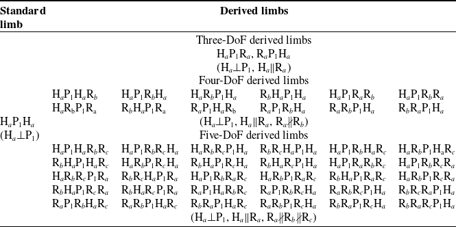
The four-DoF derived limbs and five-DoF derived limbs are obtained by adding one/two R joints whose directions are different from those of H joints to the standard limb H a P1H a . The four-DoF derived limb H a P1H a R b is
 \begin{equation} \begin{aligned} \left\{{\boldsymbol{S}}_{f{,\mathrm{H}_{a}}{\mathrm{P}_{1}}{\mathrm{H}_{a}}{\mathrm{R}_{b}}}\right\} & =\left\{\begin{array}{l} 2\tan \displaystyle\frac{\theta _{3}}{2}\left(\begin{array}{c} {\boldsymbol{s}}_{3}\\ {\boldsymbol{r}}_{3}\times {\boldsymbol{s}}_{3} \end{array}\right)\overline{\circ }\left(2\tan \displaystyle\frac{\theta _{2}}{2}\left(\begin{array}{c} {\boldsymbol{s}}_{1}\\ {\boldsymbol{r}}_{\mathrm{2}}\times {\boldsymbol{s}}_{1} \end{array}\right)+h_{2}\theta _{2}\left(\begin{array}{c} \mathbf{0}\\ {\boldsymbol{s}}_{1} \end{array}\right)\right)\\ \overline{\circ }\tau \left(\begin{array}{c} \mathbf{0}\\ {\boldsymbol{s}}_{2} \end{array}\right)\overline{\circ }\left(2\tan \displaystyle\frac{\theta _{1}}{2}\left(\begin{array}{c} {\boldsymbol{s}}_{1}\\ {\boldsymbol{r}}_{1}\times {\boldsymbol{s}}_{1} \end{array}\right)+h_{1}\theta _{1}\left(\begin{array}{c} \mathbf{0}\\ {\boldsymbol{s}}_{1} \end{array}\right)\right) \end{array}\right\}\\ & =\left\{\begin{array}{l} 2\tan \displaystyle\frac{\theta _{3}}{2}\left(\begin{array}{c} {\boldsymbol{s}}_{3}\\ {\boldsymbol{r}}_{3}\times {\boldsymbol{s}}_{3} \end{array}\right)\overline{\circ }2\tan \displaystyle\frac{\theta _{1}+\theta _{2}}{2}\left(\begin{array}{c} {\boldsymbol{s}}_{1}\\ {\boldsymbol{r}}_{\mathrm{2}}\times {\boldsymbol{s}}_{1} \end{array}\right)\\ \overline{\circ }\left(\begin{array}{c} \mathbf{0}\\ \exp \left(\theta _{1}\left[{\boldsymbol{s}}_{1}\times \right]-{\boldsymbol{I}}_{3}\right)\left({\boldsymbol{r}}_{2}-{\boldsymbol{r}}_{1}\right)\boldsymbol{+}\left(h_{1}\theta _{1}\boldsymbol{+}h_{2}\theta _{2}\right){\boldsymbol{s}}_{1}+\exp \left(\theta _{1}\left[{\boldsymbol{s}}_{1}\times \right]\right)\tau {\boldsymbol{s}}_{2} \end{array}\right) \end{array}\right\} \end{aligned} \end{equation}
where
 ${\boldsymbol{s}}_{3}\neq {\boldsymbol{s}}_{\mathrm{1}}, {\boldsymbol{s}}_{1}\bot {\boldsymbol{s}}_{2}$
and
 $\left(\begin{array}{c} \mathbf{0}\\ \exp (\theta _{1}[{\boldsymbol{s}}_{1}\times]-{\boldsymbol{I}}_{3})({\boldsymbol{r}}_{2}-{\boldsymbol{r}}_{1})\boldsymbol{+}(h_{1}\theta _{1}\boldsymbol{+}h_{2}\theta _{2}){\boldsymbol{s}}_{1}+\exp (\theta _{1}[{\boldsymbol{s}}_{1}\times])\tau {\boldsymbol{s}}_{2} \end{array}\right)$
is the translation on helicoid.
The five-DoF derived limb H a P1H a R b R c is formulated as
 \begin{equation} \begin{aligned} \left\{{\boldsymbol{S}}_{f{,\mathrm{H}_{a}}{\mathrm{P}_{1}}{\mathrm{H}_{a}}{\mathrm{R}_{b}}{\mathrm{R}_{c}}}\right\} & =\left\{\begin{array}{l} 2\tan \displaystyle\frac{\theta _{4}}{2}\left(\begin{array}{c} {\boldsymbol{s}}_{4}\\ {\boldsymbol{r}}_{4}\times {\boldsymbol{s}}_{4} \end{array}\right)\overline{\circ }2\tan \displaystyle\frac{\theta _{3}}{2}\left(\begin{array}{c} {\boldsymbol{s}}_{3}\\ {\boldsymbol{r}}_{3}\times {\boldsymbol{s}}_{3} \end{array}\right)\overline{\circ }\left(2\tan \displaystyle\frac{\theta _{2}}{2}\left(\begin{array}{c} {\boldsymbol{s}}_{1}\\ {\boldsymbol{r}}_{\mathrm{2}}\times {\boldsymbol{s}}_{1} \end{array}\right)+h_{2}\theta _{2}\left(\begin{array}{c} \mathbf{0}\\ {\boldsymbol{s}}_{1} \end{array}\right)\right)\\ \overline{\circ }\tau \left(\begin{array}{c} \mathbf{0}\\ {\boldsymbol{s}}_{2} \end{array}\right)\overline{\circ }\left(2\tan \displaystyle\frac{\theta _{1}}{2}\left(\begin{array}{c} {\boldsymbol{s}}_{1}\\ {\boldsymbol{r}}_{1}\times {\boldsymbol{s}}_{1} \end{array}\right)+h_{1}\theta _{1}\left(\begin{array}{c} \mathbf{0}\\ {\boldsymbol{s}}_{1} \end{array}\right)\right) \end{array}\right\}\\ & =\left\{\begin{array}{l} 2\tan \displaystyle\frac{\theta _{4}}{2}\left(\begin{array}{c} {\boldsymbol{s}}_{4}\\ {\boldsymbol{r}}_{4}\times {\boldsymbol{s}}_{4} \end{array}\right)\overline{\circ }2\tan \displaystyle\frac{\theta _{3}}{2}\left(\begin{array}{c} {\boldsymbol{s}}_{3}\\ {\boldsymbol{r}}_{3}\times {\boldsymbol{s}}_{3} \end{array}\right)\overline{\circ }2\tan \displaystyle\frac{\theta _{1}+\theta _{2}}{2}\left(\begin{array}{c} {\boldsymbol{s}}_{1}\\ {\boldsymbol{r}}_{\mathrm{2}}\times {\boldsymbol{s}}_{1} \end{array}\right)\\ \overline{\circ }\left(\begin{array}{c} \mathbf{0}\\ \exp \left(\theta _{1}\left[{\boldsymbol{s}}_{1}\times \right]-{\boldsymbol{I}}_{3}\right)\left({\boldsymbol{r}}_{2}-{\boldsymbol{r}}_{1}\right)\boldsymbol{+}\left(h_{1}\theta _{1}\boldsymbol{+}h_{2}\theta _{2}\right){\boldsymbol{s}}_{1}+\exp \left(\theta _{1}\left[{\boldsymbol{s}}_{1}\times \right]\right)\tau {\boldsymbol{s}}_{2} \end{array}\right) \end{array}\right\} \end{aligned} \end{equation}
where
 ${\boldsymbol{s}}_{4}\neq {\boldsymbol{s}}_{3}\neq {\boldsymbol{s}}_{1}, {\boldsymbol{s}}_{1}\bot {\boldsymbol{s}}_{2}$
and
 $\left(\begin{array}{c} \mathbf{0}\\ \exp (\theta _{1}[{\boldsymbol{s}}_{1}\times]-{\boldsymbol{I}}_{3})({\boldsymbol{r}}_{2}-{\boldsymbol{r}}_{1})\boldsymbol{+}(h_{1}\theta _{1}\boldsymbol{+}h_{2}\theta _{2}){\boldsymbol{s}}_{1}+\exp (\theta _{1}[{\boldsymbol{s}}_{1}\times])\tau {\boldsymbol{s}}_{2} \end{array}\right)$
is the translation on helicoid.
Other four/five-DoF derived limbs can be generated by the nature of finite screw theory, and we list all derived limbs in Table 3, and typical assembly diagrams are illustrated in Figure 24.
Standard and derived limbs generating translations on helicoid.

Typical assembly diagrams of robots.

5.2. Synthesis of closed-loop robots for machining and manufacturing of helical tubes
Due to the fact that the generatrix of helical tube is a circle and the generating line is a helix, the robot generating translations on helical tube is composed of a kinematic limb which generates translations on helical tube and a kinematic limb generating three-DoF translations.
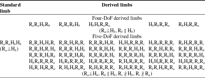
The four-DoF standard limb R a R a H b H b which generates translations on a helical tube is shown in Eq. (9), and there are five four-DoF derived limbs. The derived limb R a R a H b R b is
 \begin{equation} \begin{aligned}\left\{{\boldsymbol{S}}_{f{,\mathrm{R}_{a}}{\mathrm{R}_{a}}{\mathrm{H}_{b}}{\mathrm{R}_{b}}}\right\} & =\left\{\begin{array}{l} 2\tan \displaystyle\frac{\theta _{4}}{2}\left(\begin{array}{c} {\boldsymbol{s}}_{2}\\ {\boldsymbol{r}}_{4}\times {\boldsymbol{s}}_{2} \end{array}\right)\overline{\circ }\left(2\tan \displaystyle\frac{\theta _{3}}{2}\left(\begin{array}{c} {\boldsymbol{s}}_{2}\\ {\boldsymbol{r}}_{3}\times {\boldsymbol{s}}_{2} \end{array}\right)+h_{1}\theta _{3}\left(\begin{array}{c} \mathbf{0}\\ {\boldsymbol{s}}_{2} \end{array}\right)\right)\\ \overline{\circ }2\tan \displaystyle\frac{\theta _{2}}{2}\left(\begin{array}{c} {\boldsymbol{s}}_{1}\\ {\boldsymbol{r}}_{2}\times {\boldsymbol{s}}_{1} \end{array}\right)\overline{\circ }2\tan \displaystyle\frac{\theta _{1}}{2}\left(\begin{array}{c} {\boldsymbol{s}}_{1}\\ {\boldsymbol{r}}_{1}\times {\boldsymbol{s}}_{1} \end{array}\right) \end{array}\right\}\\ & =\left\{\begin{array}{l} 2\tan \displaystyle\frac{\theta _{4}+\theta _{3}}{2}\left(\begin{array}{c} {\boldsymbol{s}}_{2}\\ {\boldsymbol{r}}_{4}\times {\boldsymbol{s}}_{2} \end{array}\right)\overline{\circ }2\tan \displaystyle\frac{\theta _{2}+\theta _{1}}{2}\left(\begin{array}{c} {\boldsymbol{s}}_{1}\\ {\boldsymbol{r}}_{2}\times {\boldsymbol{s}}_{1} \end{array}\right)\\ \overline{\circ }\left(\begin{array}{c} \mathbf{0}\\ \exp \left(\left(\theta _{1}+\theta _{2}\right)\left[{\boldsymbol{s}}_{1}\times \right]\right)\left(\exp \left(\theta _{3}\left[{\boldsymbol{s}}_{2}\times \right]-{\boldsymbol{I}}_{3}\right)\left({\boldsymbol{r}}_{4}-{\boldsymbol{r}}_{3}\right)+h_{1}\theta _{3}{\boldsymbol{s}}_{2}\right) \end{array}\right) \end{array}\right\} \end{aligned} \end{equation}
Equation (32) elaborates the finite screw of the derived limb R
a
R
a
H
b
R
b
, where
 $\mathrm{R}_{a}\bot \mathrm{H}_{b}, \mathrm{H}_{b}\parallel \mathrm{R}_{b}$
.
 $\left(\begin{array}{c} \mathbf{0}\\ \exp ((\theta _{1}+\theta _{2})[{\boldsymbol{s}}_{1}\times])(\exp (\theta _{3}[{\boldsymbol{s}}_{2}\times]-{\boldsymbol{I}}_{3})({\boldsymbol{r}}_{4}-{\boldsymbol{r}}_{3})+h_{1}\theta _{3}{\boldsymbol{s}}_{2}) \end{array}\right)$
is the translation on the helical tube which is equivalent with the translation generated by the R
a
R
a
H
b
H
b
limb.
The five-DoF derived limb H b H b R a R a Rc is
 \begin{equation} \begin{aligned} \left\{{\boldsymbol{S}}_{f{,\mathrm{H}_{b}}{\mathrm{H}_{b}}{\mathrm{R}_{a}}{\mathrm{R}_{a}}{\mathrm{R}_{c}}}\right\} & =\left\{\begin{array}{l} 2\tan \displaystyle\frac{\theta _{5}}{2}\left(\begin{array}{c} {\boldsymbol{s}}_{3}\\ {\boldsymbol{r}}_{5}\times {\boldsymbol{s}}_{3} \end{array}\right)\overline{\circ }2\tan \displaystyle\frac{\theta _{4}}{2}\left(\begin{array}{c} {\boldsymbol{s}}_{2}\\ {\boldsymbol{r}}_{4}\times {\boldsymbol{s}}_{1} \end{array}\right)\overline{\circ }2\tan \displaystyle\frac{\theta _{3}}{2}\left(\begin{array}{c} {\boldsymbol{s}}_{2}\\ {\boldsymbol{r}}_{3}\times {\boldsymbol{s}}_{1} \end{array}\right)\\ \overline{\circ }\left(2\tan \displaystyle\frac{\theta _{2}}{2}\left(\begin{array}{c} {\boldsymbol{s}}_{1}\\ {\boldsymbol{r}}_{2}\times {\boldsymbol{s}}_{1} \end{array}\right)+h_{2}\theta _{2}\left(\begin{array}{c} \mathbf{0}\\ {\boldsymbol{s}}_{1} \end{array}\right)\right)\overline{\circ }\left(2\tan \displaystyle\frac{\theta _{1}}{2}\left(\begin{array}{c} {\boldsymbol{s}}_{1}\\ {\boldsymbol{r}}_{1}\times {\boldsymbol{s}}_{1} \end{array}\right)+h_{1}\theta _{1}\left(\begin{array}{c} \mathbf{0}\\ {\boldsymbol{s}}_{1} \end{array}\right)\right) \end{array}\right\}\\ & =\left\{\begin{array}{l} 2\tan \displaystyle\frac{\theta _{5}}{2}\left(\begin{array}{c} {\boldsymbol{s}}_{3}\\ {\boldsymbol{r}}_{5}\times {\boldsymbol{s}}_{3} \end{array}\right)\overline{\circ }2\tan \displaystyle\frac{\theta _{4}+\theta _{3}}{2}\left(\begin{array}{c} {\boldsymbol{s}}_{2}\\ {\boldsymbol{r}}_{4}\times {\boldsymbol{s}}_{2} \end{array}\right)\overline{\circ }2\tan \displaystyle\frac{\theta _{2}+\theta _{1}}{2}\left(\begin{array}{c} {\boldsymbol{s}}_{1}\\ {\boldsymbol{r}}_{2}\times {\boldsymbol{s}}_{1} \end{array}\right)\overline{\circ }\\ \left(\begin{array}{c} \mathbf{0}\\ \begin{array}{c} \exp \left(\left(\theta _{1}+\theta _{2}\right)\left[{\boldsymbol{s}}_{1}\times \right]\right)\left(\exp \left(\theta _{3}\left[{\boldsymbol{s}}_{2}\times \right]-{\boldsymbol{I}}_{3}\right)\left({\boldsymbol{r}}_{4}-{\boldsymbol{r}}_{3}\right)\right)\\ +\exp \left(\theta _{1}\left[{\boldsymbol{s}}_{1}\times \right]-{\boldsymbol{I}}_{3}\right)\left({\boldsymbol{r}}_{2}-{\boldsymbol{r}}_{1}\right)+\left(h_{2}\theta _{2}+h_{1}\theta _{1}\right){\boldsymbol{s}}_{1} \end{array} \end{array}\right) \end{array}\right\} \end{aligned} \end{equation}
Equation (33) gives the process of obtaining translations on helical tubes, where
 $\mathrm{R}_{a}\bot \mathrm{H}_{b}, \mathrm{R}_{c}\nparallel \mathrm{H}_{b}, \mathrm{R}_{c}\nparallel \mathrm{R}_{a}$
and the last factor in Eq. (33) is the translation on the helical tube, which is equivalent with the translation generated by the R
a
R
a
H
b
H
b
limb.
Other four/five-DoF derived limbs can be generated by the nature of finite screw theory, and we list all four/five-DoF derived limbs in Table 4. and typical assembly diagrams are illustrated in Figure 25.
Standard and derived limbs generating translations on helical tube.

Typical assembly diagrams of robots for machining and manufacturing of helical tubes.

6. Conclusions
A general approach for type synthesis of closed-loop robots for machining and manufacturing quadric surfaces is proposed by employing finite screw. Robots capable of generating translations on toruses, helicoids, and helical tubes are presented, leading to the following conclusions.
(1) Based upon the existing works, a novel approach for synthesizing closed-loop robots capable of machining and manufacturing various quadric surfaces is proposed. Different compositions of generatrices and generating lines are illustrated and expressed for generating translations on quadric surfaces.
(2) A closed-loop robot generating translations on torus is synthesized to validate the feasibility of the proposed approach. Both standard and derived types of robots are obtained, along with the assembly conditions for these robots.
(3) Closed-loop robots generating translations on helicoid and helical tube are synthesized through following the same manner, and all derived limbs of robots are listed.
This paper presents a systematic approach to synthesizing robots for machining and manufacturing quadric surfaces. These robots have potential applications in design and development of industrial processing equipment for complex curved parts and large components. By leveraging the structural properties of the robots, these robots can ensure precise machining trajectories and achieve high-precision machining results. Robots generating translations on complex quadric surfaces, such as toruses, helicoids, and helical tubes, have a wide range of engineering applications, which not only improve the performance and stability of equipment but also provide a robust foundation for innovation and development across various fields.
Author contribution
Jiahao Song and Shuofei Yang conceived and designed the study. Jiahao Song wrote the article, Shuofei Yang and Yunwen Zhang revised the article. Zhengjun Fang and Tianrui Zou were involved in the drawing of this paper.
Financial support
This research work is supported by the National Natural Science Foundation of China (NSFC) [Grant No. 52305042].
Competing interests
The authors declare no conflicts of interest exist.
Ethical approval
Not applicable.
Appendix
Appendix A. The expressions of the finite screw of R, P, and H joints, and the details of the derivation of the finite screw generated by a helical joint
The finite motion of the R joint, as shown in Figure A1, can be expressed using finite screw theory as
 \begin{equation} \left\{{\boldsymbol{S}}_{f}\right\}=\left\{2\tan \displaystyle\frac{\theta }{2}\left(\begin{array}{c} {\boldsymbol{s}}\\ {\boldsymbol{r}}\times {\boldsymbol{s}} \end{array}\right)\right\} \end{equation}
In Eq. (A1),
 ${\boldsymbol{s}}$
(
 $\| {\boldsymbol{s}}\| =1$
) is denoted as the unit direction vector of the R joint axis,
 ${\boldsymbol{r}}$
represents the position vector of the R joint, and
 $\theta$
is the angle of rotation of the kinematic joint from its initial position.
Similarly, the finite screw of the P joint and the H joint can be expressed as follows, as shown in Figure A2, A3.
 \begin{equation} \left\{{\boldsymbol{S}}_{f}\right\}=\left\{\tau \left(\begin{array}{c} \mathbf{0}\\ {\boldsymbol{s}} \end{array}\right)\right\} \end{equation}
where
 ${\boldsymbol{s}}$
(
 $\| {\boldsymbol{s}}\| =1$
) represents the unit direction vector of the motion of P joint, and
 $\tau$
represents the distance P joint has translated from its initial position.
 \begin{equation} \left\{{\boldsymbol{S}}_{f}\right\}=\left\{2\tan \displaystyle\frac{\theta }{2}\left(\begin{array}{c} {\boldsymbol{s}}\\ {\boldsymbol{r}}\times {\boldsymbol{s}} \end{array}\right)+h\theta \left(\begin{array}{c} \mathbf{0}\\ {\boldsymbol{s}} \end{array}\right)\right\} \end{equation}
where the denotations of
 $\theta, {\boldsymbol{r}}, {\boldsymbol{s}}$
can be referred to those in Eq. (A3) and
 $h$
is the pitch of H joint. (the ratio of the translation distance along the axis to the angle of rotation around the axis)
The motion generated by a helical joint consists of a rotation and a translation about the same axis as the rotation. We define the pitch of the helical joint to be the ratio of translation to rotation,
 $h\colon =d/\theta$
(assuming
 $\theta \neq 0$
). Thus, the net translational motion after rotating by
 $\theta$
radians is
 $h\theta$
. We represent the expression of the finite screw generated by a helical joint as
 \begin{equation} \begin{aligned} \left\{{\boldsymbol{S}}_{f,\mathrm{H}}\right\} & =\left\{2\tan \displaystyle\frac{\theta }{2}\left(\begin{array}{c} {\boldsymbol{s}}\\ {\boldsymbol{r}}\times {\boldsymbol{s}} \end{array}\right)\overline{\circ }h\theta \left(\begin{array}{c} \mathbf{0}\\ {\boldsymbol{s}} \end{array}\right)\right\}\\ & =\left\{\displaystyle\frac{2\tan \displaystyle\frac{\theta }{2}\left(\begin{array}{c} {\boldsymbol{s}}\\ {\boldsymbol{r}}\times {\boldsymbol{s}} \end{array}\right)+h\theta \left(\begin{array}{c} \mathbf{0}\\ {\boldsymbol{s}} \end{array}\right)-\frac{1}{2}\times 2\tan \displaystyle\frac{\theta }{2}\left(\begin{array}{c} {\boldsymbol{s}}\\ {\boldsymbol{r}}\times {\boldsymbol{s}} \end{array}\right)\times h\theta \left(\begin{array}{c} \mathbf{0}\\ {\boldsymbol{s}} \end{array}\right)}{1}\right\}\\ & =\left\{2\tan \displaystyle\frac{\theta }{2}\left(\begin{array}{c} {\boldsymbol{s}}\\ {\boldsymbol{r}}\times {\boldsymbol{s}} \end{array}\right)+h\theta \left(\begin{array}{c} \mathbf{0}\\ {\boldsymbol{s}} \end{array}\right)\right\} \end{aligned} \end{equation}
Finite motion of R joint.

Finite motion of P joint.

Finite motion of H joint.

Appendix B. Explanation of the screw triangle product
Finite screw synthesis operations are denoted by the symbol “
 $\overline{\circ }$
” in our manuscript and are also referred to as screw triangle product. The screw triangle product of
 ${\boldsymbol{S}}_{f,a}$
and
 ${\boldsymbol{S}}_{f,b}$
is
 ${\boldsymbol{S}}_{f,ab}$
,which can be expressed as
 \begin{equation} \begin{aligned} \left\{{\boldsymbol{S}}_{f,ab}\right\} & =\left\{{\boldsymbol{S}}_{f,a}\right\}\overline{\circ }\left\{{\boldsymbol{S}}_{f,b}\right\}\\ & =\left\{\frac{{\boldsymbol{S}}_{f,a}+{\boldsymbol{S}}_{f,b}-\displaystyle\frac{1}{2}{\boldsymbol{S}}_{f,a}\times {\boldsymbol{S}}_{f,b}-\tan \displaystyle\frac{\theta _{a}}{2}\tan \displaystyle\frac{\theta _{b}}{2}\left(\tau _{b}\left(\begin{array}{c} \mathbf{0}\\ {\boldsymbol{s}}_{a} \end{array}\right)+\tau _{a}\left(\begin{array}{c} \mathbf{0}\\ {\boldsymbol{s}}_{b} \end{array}\right)\right)}{1-\tan \displaystyle\frac{\theta _{a}}{2}\tan \displaystyle\frac{\theta _{b}}{2}{{\boldsymbol{s}}_{a}}^{\mathrm{T}}{\boldsymbol{s}}_{b}}\right\} \end{aligned} \end{equation}
where
 ${\boldsymbol{S}}_{f,a}\times {\boldsymbol{S}}_{f,b}$
represents the screw cross-product of
 ${\boldsymbol{S}}_{f,a}$
and
 ${\boldsymbol{S}}_{f,b}$
, the corresponding operation is
 \begin{equation} {\boldsymbol{S}}_{f,a}\times {\boldsymbol{S}}_{f,\mathrm{b}}=\left(\begin{array}{c} 2\tan \displaystyle\frac{\theta _{a}}{2}{\boldsymbol{s}}_{a}\times 2\tan \displaystyle\frac{\theta _{b}}{2}{\boldsymbol{s}}_{b}\\ 2\tan \displaystyle\frac{\theta _{a}}{2}{\boldsymbol{s}}_{a}\times \left(2\tan \displaystyle\frac{\theta _{b}}{2}\left({\boldsymbol{r}}_{b}\times {\boldsymbol{s}}_{b}\right)+\tau _{b}{\boldsymbol{s}}_{b}\right)+\left(2\tan \displaystyle\frac{\theta _{a}}{2}\left({\boldsymbol{r}}_{a}\times {\boldsymbol{s}}_{a}\right)+\tau _{a}{\boldsymbol{s}}_{a}\right)\times 2\tan \displaystyle\frac{\theta _{b}}{2}{\boldsymbol{s}}_{b} \end{array}\right) \end{equation}
It is emphasized that the denotations of
 $\theta, \tau, {\boldsymbol{r}}$
, and
 ${\boldsymbol{s}}$
are consistent with those in the main text, and the symbol “
 $\times$
” represents the cross-product.
Appendix C. The proof of Eqs. (4) and (5)
The proof of Eq. (4) is as follows:
 \begin{equation} \begin{aligned} \left\{{\boldsymbol{S}}_{f\mathrm{,2R}}\right\} & =\left\{2\tan \displaystyle\frac{\theta _{2}}{2}\left(\begin{array}{c} {\boldsymbol{s}}\\ {\boldsymbol{r}}_{2}\times {\boldsymbol{s}} \end{array}\right)\overline{\circ }2\tan \displaystyle\frac{\theta _{1}}{2}\left(\begin{array}{c} {\boldsymbol{s}}\\ {\boldsymbol{r}}_{1}\times {\boldsymbol{s}} \end{array}\right)\right\}\\ & =\left\{2\tan \displaystyle\frac{\theta _{1}+\theta _{2}}{2}\left(\begin{array}{c} {\boldsymbol{s}}\\ {\boldsymbol{r}}_{2}\times {\boldsymbol{s}} \end{array}\right)\overline{\circ }\left(\begin{array}{c} \mathbf{0}\\ \left(\exp \left(\theta _{1}\left[{\boldsymbol{s}}\times \right]\right)-{\boldsymbol{I}}_{3}\right)\left({\boldsymbol{r}}_{2}-{\boldsymbol{r}}_{1}\right) \end{array}\right)\right\} \end{aligned} \end{equation}
where the denotations can be referred to those as above. Particularly, the unit direction vectors
 ${\boldsymbol{s}}$
are identical due to the nature of parallel R joints. According to the operation rules of screw product, Eq. (C1) can be expanded as
 \begin{equation} \begin{aligned} \left\{{\boldsymbol{S}}_{f,2\mathrm{R}}\right\} & =\left\{2\tan \displaystyle\frac{\theta _{2}}{2}\left(\begin{array}{c} {\boldsymbol{s}}\\ {\boldsymbol{r}}_{2}\times {\boldsymbol{s}} \end{array}\right)\overline{\circ }2\tan \displaystyle\frac{\theta _{1}}{2}\left(\begin{array}{c} {\boldsymbol{s}}\\ {\boldsymbol{r}}_{1}\times {\boldsymbol{s}} \end{array}\right)\right\}\\ & =\left\{\frac{\left(2\tan \displaystyle\frac{\theta _{1}}{2}\left(\begin{array}{c} {\boldsymbol{s}}\\ {\boldsymbol{r}}_{1}\times {\boldsymbol{s}} \end{array}\right)+2\tan \displaystyle\frac{\theta _{2}}{2}\left(\begin{array}{c} {\boldsymbol{s}}\\ {\boldsymbol{r}}_{2}\times {\boldsymbol{s}} \end{array}\right)+4\tan \displaystyle\frac{\theta _{1}}{2}\tan \displaystyle\frac{\theta _{2}}{2}\left(\begin{array}{c} \mathbf{0}\\ {\boldsymbol{r}}_{2}-{\boldsymbol{r}}_{1}-{\boldsymbol{s}}^{\mathrm{T}}\left({\boldsymbol{r}}_{2}-{\boldsymbol{r}}_{1}\right){\boldsymbol{s}} \end{array}\right)\right)}{1-\tan \displaystyle\frac{\theta _{1}}{2}\tan \displaystyle\frac{\theta _{2}}{2}}\right\} \end{aligned} \end{equation}
it can be reduced as
 \begin{equation} \left\{{\boldsymbol{S}}_{f,2\mathrm{R}}\right\}=\left\{\begin{array}{l} 2\tan \displaystyle\frac{\theta _{1}+\theta _{2}}{2}\left(\begin{array}{c} {\boldsymbol{s}}\\ {\boldsymbol{r}}_{2}\times {\boldsymbol{s}} \end{array}\right)+\left(\begin{array}{c} \mathbf{0}\\ \left(\sin \theta _{1}\left[{\boldsymbol{s}}\times \right]+\left(1-\cos \theta _{1}\right)\left[{\boldsymbol{s}}\times \right]^{2}\right)\left({\boldsymbol{r}}_{2}-{\boldsymbol{r}}_{1}\right) \end{array}\right)\\ +\tan \displaystyle\frac{\theta _{1}+\theta _{2}}{2}\left(\begin{array}{c} \mathbf{0}\\ \left(\left(1-\cos \theta _{1}\right)\left[{\boldsymbol{s}}\times \right]-\sin \theta _{1}\left[{\boldsymbol{s}}\times \right]^{2}\right)\left({\boldsymbol{r}}_{2}-{\boldsymbol{r}}_{1}\right) \end{array}\right) \end{array}\right\} \end{equation}
where
 $[{\boldsymbol{s}}\times]$
is the skew-symmetric matrix of the unit vector
 ${\boldsymbol{s}}$
. According to the Euler-Rodrigues formula, it can eventually be rewritten as
 \begin{equation} \left\{{\boldsymbol{S}}_{f,2\mathrm{R}}\right\}=\left\{2\tan \displaystyle\frac{\theta _{1}+\theta _{2}}{2}\left(\begin{array}{c} {\boldsymbol{s}}\\ {\boldsymbol{r}}_{2}\times {\boldsymbol{s}} \end{array}\right)\overline{\circ }\left(\begin{array}{c} \mathbf{0}\\ \left(\exp \left(\theta _{1}\left[{\boldsymbol{s}}\times \right]\right)-{\boldsymbol{I}}_{3}\right)\left({\boldsymbol{r}}_{2}-{\boldsymbol{r}}_{1}\right) \end{array}\right)\right\} \end{equation}
The proof of Eq. (5) is as follows:
 \begin{equation} \left\{{\boldsymbol{S}}_{f,2\mathrm{H}}\right\}=\left\{\left(2\tan \displaystyle\frac{\theta _{2}}{2}\left(\begin{array}{c} {\boldsymbol{s}}\\ {\boldsymbol{r}}_{\mathrm{2}}\times {\boldsymbol{s}} \end{array}\right)+h_{2}\theta _{2}\left(\begin{array}{c} \mathbf{0}\\ {\boldsymbol{s}} \end{array}\right)\right)\overline{\circ }\left(2\tan \displaystyle\frac{\theta _{1}}{2}\left(\begin{array}{c} {\boldsymbol{s}}\\ {\boldsymbol{r}}_{1}\times {\boldsymbol{s}} \end{array}\right)+h_{1}\theta _{1}\left(\begin{array}{c} \mathbf{0}\\ {\boldsymbol{s}} \end{array}\right)\right)\right\} \end{equation}
It can be written as
 \begin{equation} \left\{{\boldsymbol{S}}_{f,2\mathrm{H}}\right\}=\left\{2\tan \displaystyle\frac{\theta _{2}}{2}\left(\begin{array}{c} {\boldsymbol{s}}\\ {\boldsymbol{r}}_{\mathrm{2}}\times {\boldsymbol{s}} \end{array}\right)\overline{\circ }h_{2}\theta _{2}\left(\begin{array}{c} \mathbf{0}\\ {\boldsymbol{s}} \end{array}\right)\overline{\circ }2\tan \displaystyle\frac{\theta _{1}}{2}\left(\begin{array}{c} {\boldsymbol{s}}\\ {\boldsymbol{r}}_{1}\times {\boldsymbol{s}} \end{array}\right)\overline{\circ }h_{1}\theta _{1}\left(\begin{array}{c} \mathbf{0}\\ {\boldsymbol{s}} \end{array}\right)\right\} \end{equation}
In Eq. (C6), it is explicit that
 $h_{2}\theta _{2}\left(\begin{array}{c} \mathbf{0}\\ {\boldsymbol{s}} \end{array}\right)\overline{\circ }2\tan \displaystyle\frac{\theta _{1}}{2}\left(\begin{array}{c} {\boldsymbol{s}}\\ {\boldsymbol{r}}_{1}\times {\boldsymbol{s}} \end{array}\right)$
is equal to
 $2\tan \displaystyle\frac{\theta _{1}}{2}\left(\begin{array}{c} {\boldsymbol{s}}\\ {\boldsymbol{r}}_{1}\times {\boldsymbol{s}} \end{array}\right)\overline{\circ }h_{2}\theta _{2}\left(\begin{array}{c} \mathbf{0}\\ {\boldsymbol{s}} \end{array}\right)$
by screw product. Eq. (C5) can eventually be written as
 \begin{equation} \begin{aligned} \left\{{\boldsymbol{S}}_{f,2\mathrm{H}}\right\} & =\left\{2\tan \displaystyle\frac{\theta _{2}}{2}\left(\begin{array}{c} {\boldsymbol{s}}\\ {\boldsymbol{r}}_{\mathrm{2}}\times {\boldsymbol{s}} \end{array}\right)\overline{\circ }2\tan \displaystyle\frac{\theta _{1}}{2}\left(\begin{array}{c} {\boldsymbol{s}}\\ {\boldsymbol{r}}_{1}\times {\boldsymbol{s}} \end{array}\right)\overline{\circ }h_{2}\theta _{2}\left(\begin{array}{c} \mathbf{0}\\ {\boldsymbol{s}} \end{array}\right)\overline{\circ }h_{1}\theta _{1}\left(\begin{array}{c} \mathbf{0}\\ {\boldsymbol{s}} \end{array}\right)\right\}\\ & =\left\{2\tan \displaystyle\frac{\theta _{1}+\theta _{2}}{2}\left(\begin{array}{c} {\boldsymbol{s}}\\ {\boldsymbol{r}}_{\mathrm{2}}\times {\boldsymbol{s}} \end{array}\right)\overline{\circ }\left(\begin{array}{c} \mathbf{0}\\ \exp \left(\theta _{1}\left[{\boldsymbol{s}}_{1}\times \right]-{\boldsymbol{I}}_{3}\right)\left({\boldsymbol{r}}_{2}-{\boldsymbol{r}}_{1}\right) \end{array}\right)\overline{\circ }\left(\begin{array}{c} \mathbf{0}\\ \left(h_{1}\theta _{1}+h_{2}\theta _{2}\right){\boldsymbol{s}} \end{array}\right)\right\}\\ & =\left\{2\tan \displaystyle\frac{\theta _{1}+\theta _{2}}{2}\left(\begin{array}{c} {\boldsymbol{s}}\\ {\boldsymbol{r}}_{\mathrm{2}}\times {\boldsymbol{s}} \end{array}\right)\overline{\circ }\left(\begin{array}{c} \mathbf{0}\\ \exp \left(\theta _{1}\left[{\boldsymbol{s}}_{1}\times \right]-{\boldsymbol{I}}_{3}\right)\left({\boldsymbol{r}}_{2}-{\boldsymbol{r}}_{1}\right)+\left(h_{1}\theta _{1}+h_{2}\theta _{2}\right){\boldsymbol{s}} \end{array}\right)\right\} \end{aligned}\end{equation}