Introduction
Radio frequency identification (RFID) is a well-known and widely-used technology. There are many standardized frequency bands for the RFID technology, but ultra-high frequency (UHF) band at 868 MHz or 915 MHz is popular for research, logistics, and remote sensing due to its relatively high data rate (40–640 kbps) and long communication range (more than 12 m) [1]. The UHF RFID technology also features large internal memory size, multiple identification/classification, collision control, and low maintenance costs. It is already successfully commercialized in transportation, logistics, and security system applications [Reference Nath, Raynolds and Want2]. Recently, numerous research efforts on the RFID-based sensing have been reported [Reference Abdulhadi and Denidni3–Reference Kim, Tentzeris and Georgiadis5]. The RFID-based sensing is a converged technology of RF energy harvesting and electromagnetic wave back-scattering technologies, which is essential for the Internet-of-Things (IoT) and extremely low power sensor network applications.
An interrogator (or a RFID reader) is a critical part of the RFID-based system because it transfers wireless RF power to the tags, and processes back-scattered power from the tags. A high-performance reader antenna is a key component of the RFID's TRx system since all wireless power and TRx signals pass through the reader antenna. First of all, the reader antennas should have broad operation bandwidth to cover global UHF RFID frequency bands (868 and 915 MHz). In most cases, a high gain circularly polarized (CP) antenna is preferred because the orientation of the receiving tag cannot be controlled and the gain of the linearly polarized tag is relatively low (<2 dBi). It is also desirable to suppress backfire radiations in order to prevent unwanted power leakage in the wrong direction.
Many reported research efforts reported in [Reference Chen, Qing and Chung6–Reference Sim, Hsu and Yang10] are stacked patch type antenna to achieve high gain, broad bandwidth, and high front-to-back ratio. However, conventional antenna designs require a thick profile in order to achieve all design requirements. In this paper, a low-profile CP antenna is proposed for UHF RFID reader applications using a mushroom type planar high impedance surface (HIS) reflector. An aperture coupled stacked patch antenna is backed by a HIS reflector in order to suppress backfire cross-pol radiation. The electromagnetic band gap (EBG) response of the HIS reflector allowed to reduce the distance between the antenna and the reflector significantly. Antenna gain was increased while maintaining impedance and axial ratio (AR) bandwidth although overall antenna thickness was remarkably decreased compared to conventional antennas. Detailed antenna design, analysis, and measurement data are presented and the effect of the HIS reflector is also analyzed. In this work, the feasibility of the HIS surface implementation at UHF band is studied and demonstrated. There are reported research efforts on patch antenna backed by a reactive surface or a HIS reflector but this work is the first application of such kind of specific configuration at UHF RFID band [Reference Qu, Shafai and Foroozesh11–Reference Sharma, Gangwar, Kanaujia, Dwari and Kumar15].
Antenna geometry
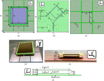
The antenna geometry and the fabricated antenna are shown in Fig. 1. The proposed antenna consists of four layers including radiation patches (layer1 and layer2), feeding network (layer3), and a HIS reflector. The proposed antenna is designed on a FR4 board, and metal (Cu) thickness (t m) is 18 μm. FR4 is relatively high loss material at UHF band but it is cost-efficient and well-matured fabrication process. The proposed antenna has low dielectric losses because a thin substrate thickness compared to the free space wavelength at UHF RFID band and most of the field is concentrated in the free space between the layers. The dielectric constant (ɛr) and loss tangent (tan δ) of a FR4 board in simulation are set to 4.4 and 0.025 at 900 MHz, respectively. The radiation patches and feeding network are printed on 150 × 150 × 1.0 mm3 (W s × L s × H s) FR4 board, and the size of the HIS reflector is 250 × 250 × 1.6 mm3 (W r × L r × H r). Each layer is separated by four nylon posts to keep the distances between layers. The layer-by-layer alignment is set by the nylon posts as well.
Antenna geometry: (a) top view, (b) antenna feeding (layer3), (c) high impedance surface (HIS) reflector (d) fabricated antenna, (e) side view, and (f) side view of the fabricated antenna.

The stacked patch structure (radiation patches on layer1 and layer2) enabled broadband radiation. Square patches are printed on layer1 and layer2, and their sizes are 127 × 127 mm3 (W 1 × L 1) and 130 × 130 mm2 (W 2 × L 2). Layer3 is a feeding layer having two coupling apertures and a coupler. A 3-dB 90˚ hybrid coupler is designed to split the input power evenly into two and make 90° phase difference. The stacked square patch antenna is fed by two H-shaped apertures to generate CP wave. The isolation port of the hybrid coupler is terminated by 50 Ω resistor (R 1). The length (Ls 1) and height (Ls 2) of the aperture are 37 and 28 mm, respectively. Four nylon posts are inserted at each corner of the antenna substrate to hold all the layers (layer1, layer2, layer3, and reflector) tightly. The radius (R post) of the nylon post is 1.75 mm. The distance between layer1 and layer2 (H 1) is 4.8 mm, and the distance between layer2 and layer3 (H 2) is 12.7 mm. The distance from the HIS reflector to the antenna (H 3) is 4.8 mm. The HIS reflector consisted of nine mushroom type unit cells. The square-shaped patch is shorted to the ground plane at the bottom of the reflector layer through a via in the middle of the patch. The size of a single patch (W c × L c) is 80 × 80 mm2 and the radius of the via (R via) is 0.5 mm. Gap (G) between the unit cells are 4 mm. The overall size of the designed antenna with the HIS reflector is 250 × 250 × 26.9 mm3 (0.71λ 0 × 0.71λ 0 × 0.076λ 0). Detailed antenna dimensions are summarized in Table 1.
Antenna size in mm

Antenna design
Aperture coupled stacked square patch antenna
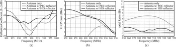
Two square radiation patches were stacked to design a broadband patch antenna [Reference Gao, Li, Leong and Yeo16]. Two patches were tightly coupled and resonance frequencies of the patches were closely located to obtain the broad impedance matching bandwidth. The square type patches have been chosen because the symmetry helps to obtain better AR when the antenna is excited. A hybrid coupler feeds the stacked patch antenna with 90° phase difference to generate CP wave. All the structures were printed on low-cost FR4 boards. The alignment and distance of each layer were maintained by the four nylon posts as shown in Fig. 1(f). The aperture coupled feeding network is easy to fabricate and assemble since there are no vertical interconnects. The alignment error was about 250 μm resulting from tolerance of FR4 PCB fabrication process. The misalignment of 250 μm was negligibly small compared to the wavelength (33–35 cm) at UHF RFID band. However, the aperture coupled stacked patch antenna usually suffers from cross-polarized backfire radiation. The more backfire radiation occurs when the ground plane on layer3 is truncated (Ws × Ls is 0.43λ 0 × 0.43λ 0 at 850 MHz) as shown in Fig. 1. One of the most efficient ways to suppress the backfire radiation is to place the antenna in the middle of a reflector or a cavity. The cavity requires vertical sidewalls to reflect the backfired EM energy and the depth of the cavity is usually as deep as λ 0/4 at the operation frequency of the antenna [Reference Wu, Wong, Lin, Zhu, He and Chen17]. It is impractical to integrate a cavity and the antenna for UHF RFID applications due to the long wavelength. Placing the antenna on a planar reflector is an attractive option to suppress the backfired waves since the reflector does not require any 3D structures. The designed antenna performance parameters, such as reflection coefficient (|S 11|), gain, and AR, are shown in Fig. 2 (dashed black line). The operation AR bandwidth of the proposed antenna is covered with universal RFID bands at 868 and 915 MHz. The designed antenna's peak CP gain was about 4.8 dBic at 890 MHz without the HIS reflector.
Antenna parameters with and without the reflectors: (a) reflection coefficient (|S 11|), (b) antenna gain, and (c) axial ratio (AR).

HIS reflector
The mushroom-type HIS has been chosen because of its symmetric geometry. The symmetricity is important in this work since the reflector should reflect CP waves. The HIS reflector was designed as reported in [Reference Sievenpiper18]. The center resonant frequency (ω 0) of the reflector can be written as (1) where Ls and Cs are surface inductance and capacitance of a unit HIS cell, respectively.


where Hr is the thickness of the reflector, Wc is the width of the metal patch, and G is the gap between the metal patches as shown in Table 1. Calculated phase of reflection coefficient from the proposed HIS reflector is shown in Fig. 3, and the operation bandwidth is highlighted in Fig. 3.
Phase of reflection coefficient of the designed HIS model.

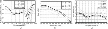
The distance between the antenna and the HIS reflector was optimized through parametric study as shown in Fig. 4. |S 11|, AR, and gain values improved as H 3 increased. |S 11| values showed relatively insensitive to the H 3 compared to the variation of gain and AR values. It should be noted that AR and gain values were almost saturate when H 3 value was larger than 5 mm. In this work, The H 3 value was chosen as 5 mm because it was the minimum value satisfying the antenna design target.
Parametric study of the distance between the antenna and the HIS reflector (H 3): (a) |S 11|, (b) RHCP antenna gain, and (c) AR.

The effects of the HIS reflector are shown in Fig. 2 (solid black line). Impedance bandwidth covered design target of 850–950 MHz and CP antenna gain values were improved by about 2 dBic. The peak gain frequency was shifted to a lower frequency at 850 MHz due to the loading effect of the reflector. AR increased slightly but it was still acceptable. It is clear that the induced image current on the HIS reflector is in-phase with the antenna.
For comparison, the HIS reflector was replaced by a PEC reflector and antenna performance parameters with the 250 × 250 mm2 PEC reflector are also shown in Fig. 2 (solid grey line). The distance (H 3) between the PEC reflector and the antenna was set to 84 mm, which was about quarter-wavelength (λ 0/4) at operation frequency in free space. Antenna gain and AR values were significantly deteriorated due to the induced out-of-phase image current on the perfect electric conductor (PEC) reflector. It is clear that the designed HIS reflector operates properly at the UHF RFID band.
Antenna measurement
Reflection coefficient (S 11), gain, and AR
The simulated and measured reflection coefficient (|S 11|) values of the proposed antenna are shown in Fig. 5(a), and the simulated data are almost the same as the measured data. The measured −al dB impedance bandwidth was broad enough to cover the UHF RFID frequency bands at 868 and 915 MHz. A small discrepancy between the measurement and simulation results were due to fabrication errors. The fabrication errors include variation of air gaps (H 1, H 2, and H 3), layer-to-layer misalignment, and metal printing resolution (250 μm), etc.
(a) Simulated and measured antenna's reflection coefficient (|S 11|), (b) Simulated and measured antenna gain and (c) Simulated and measured axial ratio (AR).

Figure 5(b) shows the measured CP gain values of the designed antenna in the anechoic chamber. The designed antenna has right-hand CP (RHCP) gain (co-pol) and its maximum gain is about 7.1 dBic. The measured left-hand CP (LHCP) gain (cross-pol) values are also shown in Fig. 5(b). The measured RHCP and LHCP gain values are in good agreement with the simulated gain values. The simulated and measured AR values are shown in Fig. 5(c). Both simulated and measured data are in good agreement, and the measured AR bandwidth has also covered the desired frequency bandwidth. The measured AR values of the proposed antenna are about 1.2–3.1 dB at the frequency band of interest (850–950 MHz).
Radiation patterns
The measured and simulated normalized radiation patterns at 868 and 915 MHz are shown in Figs. 6 and 7. It shows a good agreement between simulation and measurement results. The radiation patterns are maintained at the 850–950 MHz frequency band of interest. Figures 8 and 9 depict measured cross-pol (LHCP) radiation patterns with and without the HIS reflector, and the effect of the HIS reflector is clearly shown. Backfired cross-pol patterns were suppressed by 8 dB at 868 MHz and 10 dB at 915 MHz. Better backfire suppression was observed around the resonant frequency (around 900 MHz) of the HIS reflector. The performance of the designed planar HIS reflector has been experimentally verified by measuring antenna gain, AR, radiation patterns, and reflection coefficient measurements. The advantages of placing a HIS reflector under the antenna is to suppress backfire radiation although it increases antenna thickness and size due to the reflector. Antenna polarization or radar cross-section (RCS) can also be manipulated by the HIS reflector [Reference Liu, Liu and Gong14, Reference Sharma, Gangwar, Kanaujia, Dwari and Kumar15]. In [Reference Mishra, Jahagirdar and Kumar19, Reference Saeidi-Manesh and Zhang20], cross-pol gain was highly suppressed by introducing novel feeding networks. This technique has the advantage of a low antenna profile but requires a complex feeding network. It is also challenging to manipulate antenna polarization or RCS.
Measured radiation patterns at 868 MHz: (a) XZ-plane (φ = 0°) and (b) YZ-plane (φ = 90°).

Measured radiation patterns at 915 MHz: (a) XZ-plane (φ = 0°) and (b) YZ-plane (φ = 90°).

Measured radiation patterns at 868 MHz: (a) XZ-plane (φ = 0°) and (b) YZ-plane (φ = 90°).

Measured radiation patterns at 915 MHz: (a) XZ-plane (φ = 0°) and (b)YZ-plane (φ = 90°).

Antenna performance comparison
Performance comparison among reported CP patch antennas on HIS reflector and this work are summarized in Table 2. The proposed antenna design has a relatively small size in terms of wavelength because the proposed antenna has a HIS reflector consisting of only 3 × 3 unit cells. The proposed antenna is fed by a simple planar aperture structure but [Reference Agarwal, Nasimuddin and Alphones12–Reference Sharma, Gangwar, Kanaujia, Dwari and Kumar15] are fed by three dimensional (3D) vertical probes. The proposed antenna has low backfired cross-pol gain value of −7.5 dBic. Reported works shown in [Reference Chatterjee, Mohan and Dixit13–Reference Sharma, Gangwar, Kanaujia, Dwari and Kumar15] has lower backfired cross-pol gain but their reflector size is much larger than the proposed antenna.
Reported HIS Reflector-backed antennas

Conclusion
The backfire suppression technique using a HIS reflector is presented in this paper. A broadband aperture coupled stacked CP patch antenna for UHF RFID applications was backed by a mushroom-shaped HIS reflector and its operation principle was discussed. The measured antenna performance parameters, such as CP gain, AR, radiation patterns and |S 11|, agreed with the simulation very well. The proposed antenna features simple structure, broad bandwidth, and high gain compared with the reported research efforts. The presented backfire suppression technique using the HIS reflector is scalable to other applications and reduces the distance between the antenna and the reflector significantly.
Acknowledgement
This work was supported by the National Research Foundation of Korea (NRF) grant funded by the Korea government (MSIT) (No.2020R1C1C1003362) and the Air Force Office of Scientific Research under award number FA2386-19-1-0124.
 Sangkil Kim received his B.S. degree from School of Electrical and Electronics Engineering, Yonsei University (magna cum laude), Seoul, Republic of Korea in 2010. He received his M.S. and Ph.D. degrees from School of Electrical and Computer Engineering, Georgia Institute of Technology, GA, Atlanta, USA in 2012 and 2014, respectively. From 2015 to 2018, he worked at Qualcomm, Inc., San Diego, CA, USA as a senior engineer. He joined the faculty of Department of Electronics Engineering, Pusan National University, Busan, Republic of Korea in 2018. He has published 32 papers in peer-reviewed journals and 5 book chapters. Dr. Kim received the IET Premium Award Microwave, Antennas & Propagation in 2015 and KIEES Young Researcher Award in 2019. He is a member of the IEEE MTT-26 RFID, Wireless Sensors, and IoT Committee. His main research interests are mmWave phased antenna array, machine learning-assisted backscattering communication, RF biosensors, energy harvesting and printed RF electronics.